As passenger EV platforms migrate from 400V toward 800V, the vehicle-mounted on-board charger (OBC) and its companion DC-DC converter have become one of the fastest-changing power-electronics compartments. Higher battery-pack voltages permit lighter high-voltage cabling and faster AC charging, but they also raise switching losses, temperature stress and insulation demands that legacy silicon devices cannot always serve efficiently. SiC MOSFETs rated 900-1200V are moving into both the PFC/AC-DC stage and the isolated DC-DC stage, switching faster and shrinking magnetics while forcing tighter, lower-inductance laminated busbar layouts around the power modules. Unlike roadside charging hardware or the traction inverter, OBC busbars must survive the full automotive environment: vibration, thermal cycling, dust and splash, fast-charge heat and a tightly packaged enclosure. This article examines where the busbar sits in the OBC plus DC-DC architecture, how 800V and SiC change conductor design, and the reliability, thermal, insulation and lightweighting requirements that should be fixed on the component drawing before tooling release.
As passenger EV platforms migrate from 400V toward 800V, the vehicle-mounted on-board charger (OBC) and its companion DC-DC converter have become one of the fastest-changing power-electronics compartments. Higher battery-pack voltages permit lighter high-voltage cabling and faster AC charging, but they also raise switching losses, temperature stress and insulation demands that legacy silicon devices cannot always serve efficiently. SiC MOSFETs rated 900-1200V are moving into both the PFC/AC-DC stage and the isolated DC-DC stage, switching faster and shrinking magnetics while forcing tighter, lower-inductance laminated busbar layouts around the power modules. Unlike roadside charging hardware or the traction inverter, OBC busbars must survive the full automotive environment: vibration, thermal cycling, dust and splash, fast-charge heat and a tightly packaged enclosure. This article examines where the busbar sits in the OBC plus DC-DC architecture, how 800V and SiC change conductor design, and the reliability, thermal, insulation and lightweighting requirements that should be fixed on the component drawing before tooling release.
The on-board charger is the vehicle's gateway between the AC grid and the high-voltage battery pack. It performs power-factor correction (PFC), rectification and isolated DC conversion to charge the traction battery at the pack voltage, while a separate DC-DC converter steps that high voltage down to the 12V or 48V auxiliary rail that feeds lights, controllers, pumps and comfort loads. In many production programs the two functions share a housing, a cooling plate and a common control board, and the internal conductors between PFC stage, DC link, transformer, isolation barrier and output stage are increasingly implemented as laminated busbars rather than discrete cables.
This article deliberately stays inside the vehicle: it does not cover roadside public ultra-fast charging infrastructure, nor the DC-link busbars of the traction inverter. Those adjacent topics are linked for cross-reference, but the OBC and DC-DC unit has its own duty cycle, its own qualification regime and its own failure modes. Understanding that boundary prevents keyword overlap and helps engineers specify the right conductor for each compartment rather than copying an inverter drawing into a charger program.
For OEMs and tier suppliers, the OBC busbar is a safety-critical interconnect: it carries the highest continuous current inside a sealed power enclosure, must maintain dielectric integrity over the vehicle life, and contributes directly to conversion efficiency through its loop inductance and resistance. Design choices made at the busbar level affect switching spikes, snubber size, temperature rise and even the audible noise of the unit, which is why power-electronics teams now treat the busbar as a co-designed component rather than a last-minute wiring solution.
A 400V pack charges from a single-phase or three-phase AC source through a charger sized around 3.3kW, 6.6kW or 11kW; 800V platforms push three-phase AC charging toward 11kW and 22kW tiers and, more importantly, enable DC fast charging at 250kW and above. At a fixed power level, doubling the pack voltage halves the current, which reduces cable and conductor cross-section, lowers copper mass and cuts resistive losses (I squared R). The benefit is real, but it shifts engineering effort onto the semiconductor voltage rating, the insulation system and the internal power-loop layout.
On the semiconductor side, 800V-class designs need switches with headroom above the bus voltage plus switching overshoot: 900V and 1200V SiC MOSFETs became the practical choice where efficiency and power density matter. On the passive side, the DC-link capacitors, magnetics and busbars must handle higher dv/dt, higher insulation working voltages and the same or higher peak currents during boost and rectification intervals. The busbar that connects the PFC devices to the DC-link capacitor bank therefore carries both high ripple current and fast voltage transients, and its parasitic inductance directly shapes switching loss and voltage spikes.
For the DC-DC auxiliary converter, the trend runs in the opposite direction at the low-voltage side: 12V systems remain dominant, but 48V architectures for e-compressors, pumps and chassis electronics are spreading, which raises the output-side current and demands robust, low-resistance output busbars with clear creepage to the primary side. Engineers should review current-sharing design rules when parallel output paths are used, because uneven sharing creates localized hot spots that vibration and thermal cycling later expose.
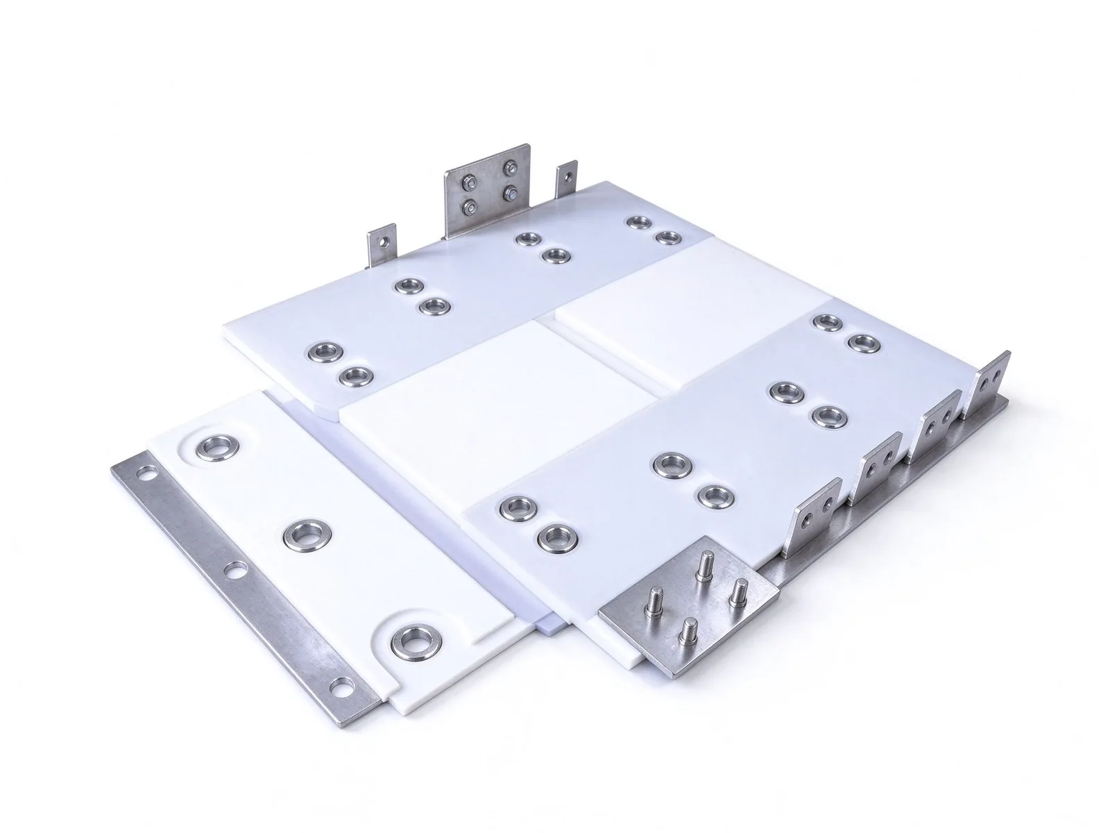
Silicon IGBTs and MOSFETs dominated earlier OBC generations, but SiC MOSFETs switch at higher frequencies with lower switching loss and a near-ideal body diode, allowing smaller boost inductors, smaller DC-link capacitors and a more compact enclosure. The trade-off is that faster switching produces higher di/dt and dv/dt, and the voltage overshoot caused by loop inductance around each switch must be suppressed by tight, symmetric commutation loops. This is precisely where laminated busbars earn their place: stacked positive and negative layers separated by thin dielectric cancel magnetic fields and keep stray inductance low.
Industry data confirms the direction of travel. The broadening SiC power module market extends from traction inverters into chargers and DC-DC converters; TrendForce reported SiC inverter penetration at 17% in 2Q25 and rising across BEVs, PHEVs and range-extended models, while dedicated 800V SiC OBC revenue grew from USD 342.8M in 2025 toward a projected USD 1.42B by 2032. OBC suppliers use SiC mainly in the PFC and isolated DC-DC stages, where efficiency maps directly into charging time and range, and where enclosure volume is at a premium.
Design implications for the busbar are concrete. First, position the DC-link capacitor bank as close as possible to the switch modules and use a laminated power bus to shorten the commutation loop. Second, balance the parallel current paths so no single die carries a disproportionate share of ripple current. Third, specify materials and insulation rated for the higher switching frequency, where the skin-effect design rules at high switching frequency matter more than in a low-frequency distribution bar. Fourth, plan for the SiC junction temperature margin when sizing the conductor and its cooling interface, because the semiconductor can run hot even when the copper bar itself looks modestly warm.
Unidirectional chargers convert AC to DC only. Bidirectional OBCs invert DC back to AC for vehicle-to-grid (V2G) grid services, vehicle-to-load (V2L) external appliances and, in some programs, vehicle-to-home backup. Market data shows bidirectional units already held roughly 59.4% of the 800V SiC OBC segment in 2025, because OEMs monetize energy flexibility rather than charging speed alone. A bidirectional topology usually combines totem-pole or Vienna PFC with an isolated dual-active-bridge or CLLC resonant DC-DC stage, and the same conductors carry power in both directions.
The busbar consequences are subtle but important. Current reversal means thermal and mechanical stress cycles run in both directions, so the conductor must be sized for the worst-case direction rather than the nominal charging rating. Reversible power also requires symmetric, low-inductance layouts on both the primary and secondary sides of the isolation transformer, and the neutral and phase conductors must be routed to cancel EMI emissions that can interfere with the vehicle radio and communication buses. Teams should review bidirectional V2G charging architectures for the system-level control context before fixing the hardware interface.
EMI filtering inside the OBC adds another busbar-shaped component: the AC input bus to the EMC filter, the filter output to the PFC stage, and the internal grounding or shielding bus. High-voltage conductors emit EMI proportional to voltage and loop area, and shielding or pairing conductors close together reduces radiated noise; our note on busbar EMI shielding design covers the screening options in more detail. For a bidirectional program, reserve layout space for the filter stage early, because retrofitting shielding after mechanical freeze usually costs more copper, more volume and more rework.
A typical integrated OBC plus DC-DC enclosure contains several distinct conductor functions, each with a different specification. The AC input bus connects the charging inlet, fuse, precharge contactor and EMC filter. The PFC output bus feeds the boost stage and the DC-link capacitor bank. The high-voltage DC bus links the OBC output to the pack interface and, in combined units, to the isolated DC-DC primary winding. The auxiliary output bus carries the stepped-down 12V or 48V current to the low-voltage battery and vehicle loads. Finally, a chassis-ground or PE bus bonds the enclosure, shields and safety earthing points.
Each function has its own current waveform: the AC input carries 50/60Hz line current plus harmonics; the DC link carries high-frequency ripple at the switching frequency; the auxiliary output carries rectified DC with its own ripple. Conductor sizing therefore cannot rely on a single DC ampacity table; engineers should consult the busbar current-capacity explanation and the harmonic-current rating guidance to convert RMS ripple and duty cycle into a credible temperature-rise budget. The ampacity calculation guide provides the step-by-step cross-section method for enclosed, forced-air or liquid-cooled conditions.
Mechanically, these internal busbars bolt or solder to power modules, capacitors, transformer terminals and PCB power stages. Connection points define the terminal family: threaded studs, blade tabs, press-fit pins and welded joints each impose different plating, torque and clearance requirements. Cross-referencing terminal type selection and power-module interface design helps align the OBC conductor with the component supplier's recommended mounting interface, reducing the risk of a redesign after samples are built.
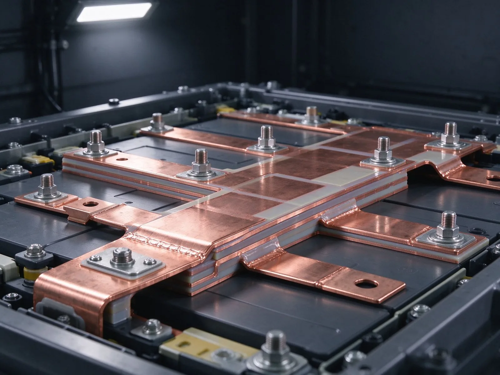
Stray inductance in the switching loop stores energy that returns as a voltage spike at turn-off: V spike equals L loop times di/dt. With SiC switching edges measured in tens of nanoseconds, even a few nanohenries per millimeter of copper path can produce spikes that push the switch beyond its safe operating area and demand extra snubber or device derating. A multi-layer laminated busbar interleaves positive and negative copper layers with a thin dielectric, producing overlapping parallel plates whose opposing fields cancel; loop inductances below 20nH for the commutation path are routinely achieved where the layout keeps the capacitor bank, switches and DC output on adjacent layers.
Layer count and materials follow the insulation and voltage requirements. SHANYUAN manufactures insulated laminated busbars in one to six-plus layers using C11000 copper with PET, Nomex and DLF insulation systems, and its standard design targets a controlled 30°C temperature-rise envelope; the multi-layer laminated busbar selection note explains how layer count trades against space, cost and creepage. For an 800V OBC, the isolation barrier between primary and secondary of the DC-DC stage is the critical dielectric region: it must withstand working voltage, transient overvoltage and partial-discharge-free operation, which the partial-discharge-free design guidance addresses.
Verification should include measured loop inductance rather than simulation alone. Loop-inductance measurement techniques describe the impedance-analyzer and TDR methods used to validate commutation loops, while the FEM impedance simulation guide covers the virtual model that should correlate with hardware. Good practice fixes the busbar to the mechanical stack early, because adding holes, standoffs and routing channels after electrical layout freezes usually forces compromises that raise inductance or weaken the dielectric margin.
An OBC mounted under the hood or in the rear trunk experiences continuous road vibration, engine or motor excitation, shock events and rapid thermal cycles that a stationary industrial power supply never sees. Internal busbars are not just conductors; they are structural elements held by studs, brackets, standoffs and potting features, and each attachment point is a potential failure. Loosening under cyclic load, fretting wear at clamped interfaces, and fatigue cracking near bend radii or holes are classic root causes in field returns. The vibration and bolted-joint design rules describe torque control, washer selection, spring-washer limitations and anti-loosening hardware for exactly this environment.
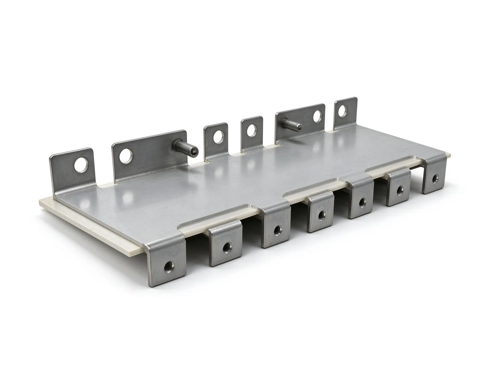
ISO 16750 sets the frame for vehicle environmental qualification: it defines separate requirement classes for electrical loads, mechanical vibration and shock, thermal and climatic conditions, and chemical exposure to oils, fluids and cleaners. The OBC program sheet should state which class applies to each axis, and the internal busbar drawing should inherit those requirements rather than redefining them. Shock tests verify that unsupported busbar ends do not contact neighboring high-voltage parts, while vibration sweeps expose resonances where the bar amplifies motion at a specific frequency; mechanical simulation of thermal expansion and dynamic motion should precede bench testing, following the approach summarized in the Aptiv engineering reference on optimizing busbars for advanced vehicle applications.
Fretting corrosion deserves specific attention. At bolted or pressed interfaces under micro-motion, soft tin-plated surfaces can oxidize and build a resistive oxide powder, raising joint resistance over time; the thermal-cycling reliability qualification guide pairs vibration data with temperature-cycle results that reveal creeping loosening. Design mitigations include flexible sections away from terminals, controlled clamp pressure, hardened or plated contact faces, and periodic resistance checks during validation. Rigidity helps automated assembly and positioning, but a small flexible zone or compensated bend near the terminal can absorb movement without fretting the main joint, a principle covered in flexible versus rigid busbar selection.
OBCs run in sealed enclosures with limited air exchange, so heat generated in semiconductors, capacitors and busbar resistance must flow to a cold plate or fins through the enclosure. Copper bar resistance contributes copper losses proportional to the square of the RMS current, and the bar also acts as a heat spreader from module terminals toward mounting points. Large flat cross-sections have high surface-to-volume ratios and radiate heat effectively; the engineering literature notes that flat busbars can behave as a passive cooling element during high-power charging, reducing reliance on forced airflow and lowering acoustic fan load.
Thermal design starts from the operating duty cycle, not the peak rating. An OBC charges intermittently: the worst case may be repeated AC fast charges in high ambient temperature with the vehicle in traffic, driving junction and conductor temperatures upward for sustained intervals. Engineers should compute steady-state and transient losses, place the lowest-resistance path through heat-generating components, and verify temperature rise on the assembled unit; the busbar thermal-management design methods note covers natural convection, conduction to cold plate, and material selection. The voltage-drop and power-loss guide converts conductor resistance into Watts per meter and helps balance copper mass against efficiency targets.
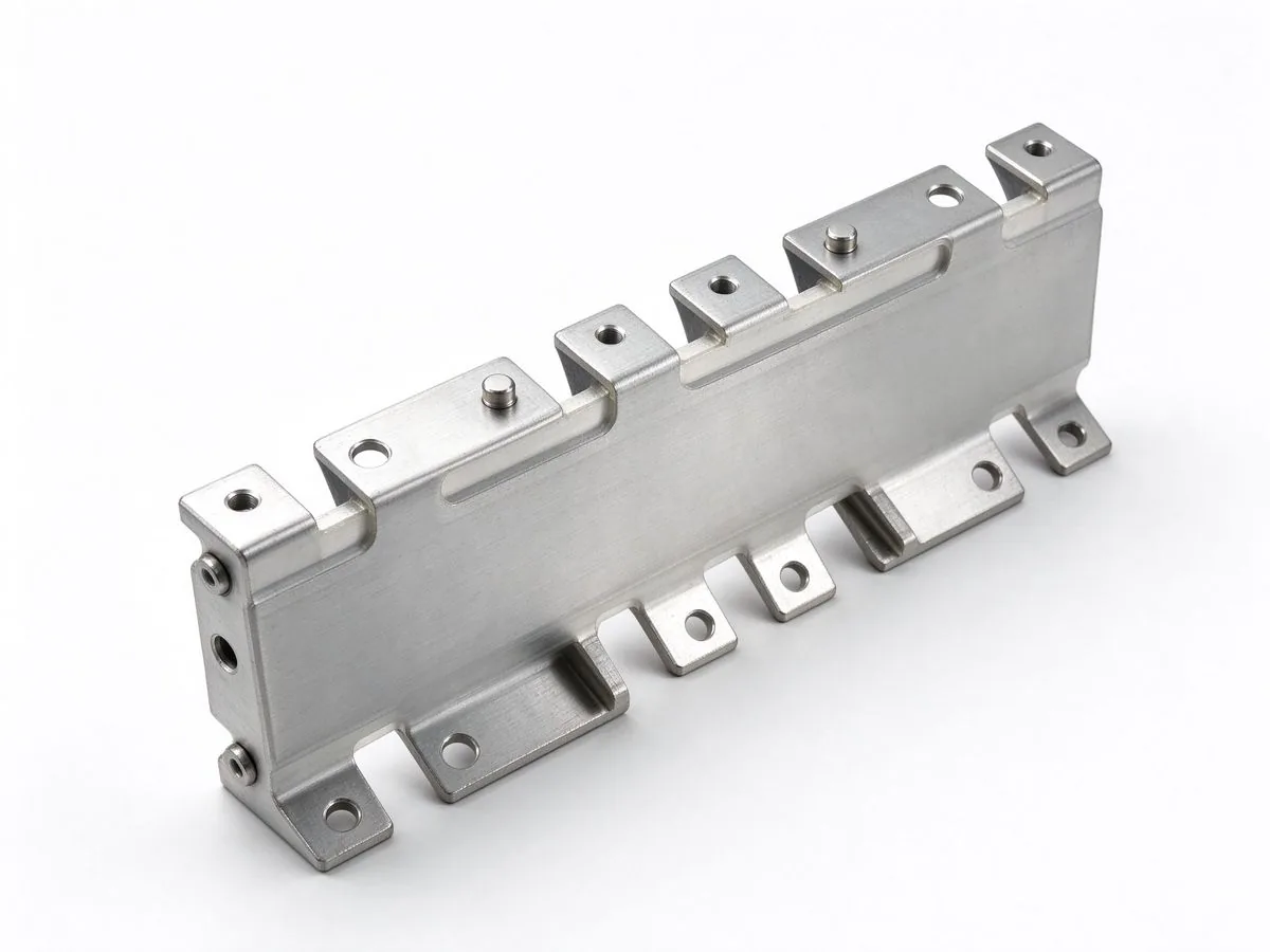
Dielectric choice constrains the thermal envelope. PET, Nomex and DLF films each have different continuous-temperature limits, and insulation that delaminates after repeated hot cycles can expose the copper to neighboring parts; the high-voltage dielectric selection guide compares thermal class, thickness and partial-discharge behavior. SHANYUAN's laminated busbars are designed around a controlled 30°C temperature-rise criterion on typical applications, which gives a conservative margin for intermittent OBC duty, but the final rating must be confirmed on the actual cooling environment, contact finish and current waveform with measured thermocouple data rather than a catalog claim.
Higher working voltage changes the insulation budget fundamentally. Clearance (air distance between conductive parts) scales with peak working voltage and pollution degree, while creepage (distance along the insulating surface) depends on material comparative tracking index and altitude derating. Inside an OBC enclosure, pollution degree 2 or 3, condensation risk and coatings mean surface tracking paths must be generous, and the reinforced insulation between primary and secondary of the DC-DC converter must satisfy reinforced-class requirements under applicable component standards. Routing high-voltage and low-voltage conductors on separate layers or separated edges reduces the chance of flashover.
The insulation system includes the busbar film or coating, potting compound, slot liners, connector boots and standoffs; one weak link in the chain defines the system rating. The creepage and clearance design reference gives the dimensional logic for pollution degree and overvoltage category, while insulation testing procedures define hipot, dielectric withstand and resistance measurements used to prove the finished part. Partial-discharge-free design matters more at 800V because surface voids in thin insulation can begin corona activity that erodes film over thousands of operating hours.
Insulation procurement also affects cost and lead time. The insulation material procurement guide outlines PET, Nomex, DLF and film-backed adhesive options, supply considerations and why specification sheets should state continuous temperature, dielectric strength and tracking index rather than a vague rating. For OBC programs subject to environmental regulations and recyclability expectations, teams should also keep the finish and insulation data aligned with the EU battery regulation implications for busbar content, because declarable substances increasingly flow into the vehicle BOM documentation.
Every kilogram removed from a vehicle extends range, so OBC suppliers compete on power density in Watts per kilogram and liters per kilowatt. Copper dominates the busbar mass, but the laminated stack also includes insulation, terminals and fasteners. Weight reduction levers include optimized cross-sections sized from measured loss budgets rather than conservative rules of thumb, current sharing across parallel plates that permits thinner individual layers, selective copper removal in low-current regions, and copper-alloy or aluminum substitution where the thermal and electrical trade-offs allow. The aluminum versus copper comparison weighs density, resistivity, corrosion and joint stability for such substitutions; OBC internal conductors usually favor copper because compact volume and low resistance outweigh the mass penalty, but output-stage aluminum is used in select programs.
Parallel paths create their own design risk. When two or more laminated layers or bar sections share current, unequal impedance from routing length, contact resistance and terminal position forces one path to carry more current, and that path heats more, which raises its resistance further in a feedback loop. Current sharing must be addressed in layout symmetry: equal path lengths, matched contact pressure, consistent plating and balanced terminal placement. The current-sharing design guide details how to model and verify symmetry, and thermal imaging during validation should confirm that the hottest parallel branch matches the model rather than assumptions.
Lightweighting must never come at the expense of short-circuit and mechanical strength. A fault current in the vehicle high-voltage system produces massive magnetic forces and rapid heating; the conductor and its mountings must survive the specified short-time withstand rating, as covered in the short-circuit withstand design reference. Teams should therefore run the optimization loop between electrical loss, mass, insulation clearance and fault duty before releasing geometry, and document the trade-offs in the design review record that supports later qualification testing.
Automotive qualification combines component-level and assembly-level tests, sequenced so that electrical checks happen before and after environmental stressors. A typical program starts with dimensional and visual inspection, dielectric withstand (hipot) at the specified test voltage, insulation resistance and contact-resistance measurement at defined torque. It then proceeds to thermal cycling, humidity exposure, vibration and shock on the defined axes, salt or chemical exposure where relevant, and a final re-measurement of resistance and dielectric integrity to prove no degradation. Pass criteria should be written as numbers: maximum joint micro-ohms after cycling, minimum hipot breakdown margin, and no delamination, cracking or fretting material on the inspection faces.
The environmental test family traces to ISO 16750, which separates electrical, mechanical, thermal, climatic and chemical load classes; manufacturers also reference customer-specific requirements such as LV-class standards and component-level norms depending on the program. The thermal-cycling reliability qualification guide explains dwell time, number of cycles and post-test resistance trending, while the common busbar failure modes catalogues the defect patterns engineers should look for during failure analysis: open cracks, peeled insulation, burned plating, loosened studs and overheated interfaces.
Sample size and traceability matter as much as test names. A PPAP-style record should include material certificates for the C11000 copper heat lot, insulation material datasheets, plating finish reports, torque specifications, and the measurement equipment calibration history. Early prototypes should follow the quick-sample and prototyping workflow to catch geometry or insulation issues before hard tooling, and the RFQ record should carry test requirements explicitly; the RFQ and supplier evaluation criteria describe the compliance documentation a buyer should request. Foundational manufacturing controls, covered in the laminated busbar manufacturing process overview, determine whether good test results repeat across production lots rather than appearing only on golden samples.
Three adjacent domains share keywords with this article, and keeping their boundaries clear improves both engineering decisions and site content quality. First, charging-infrastructure busbars sit in wallboxes, DC fast chargers and cabinet distribution; they are installed outdoors, rated for continuous station duty, and governed by installation and utility codes rather than vehicle vibration. The dedicated note on the ultra-fast charging network build-out covers those demand dynamics and uses different reliability assumptions.
Second, traction-inverter DC-link busbars connect SiC or IGBT modules to DC-link capacitors in the drive inverter; they share the low-inductance laminated language but operate under continuous motor current, different cooling conditions and different fault duty. Our SiC and IGBT DC-link busbar analysis treats that compartment in depth, including semiconductor switching losses and inverter packaging constraints. Third, pack-level busbars connect cells and modules inside the battery enclosure, exposed to cell-level vibration, swelling tolerance and safety-fuse requirements; EV battery busbar trends cover those selections, including flexible layer designs that absorb cell expansion.
The OBC and DC-DC unit sits between these worlds: vehicle environment but power-electronics duty, intermittent charging cycles but a sealed enclosure, high-frequency switching but lower continuous current than the traction inverter. When specifying parts, name the compartment in the document title, define the duty cycle and qualification class, and reference the adjacent note only where a topic genuinely overlaps. This discipline prevents duplicated claims, keeps each landing page focused on a distinct buying intent, and gives engineers a navigable internal link path from system trend analysis down to component design guidance and manufacturing practice.
Rizhao Shanyuan Electronic Components Co., Ltd. (SHANYUAN), established in March 2012 and operating a 17,200 m² plant at Taoyuan Village, Wulian Street, Rizhao, Shandong, China, supplies insulated laminated busbars to customers in more than 20 countries. Its product range covers one to six-plus layers, rated up to roughly 1000A, built on C11000 copper with PET, Nomex and DLF insulation options, a controlled 30°C temperature-rise design basis, tin-plated contact surfaces, and M6/M8 threaded studs, blade terminals and welded terminal arrangements. These capabilities support power-electronics compartments including on-board chargers, DC-DC converters, inverter interfaces and energy-storage converters, adapted to the customer's voltage, current, cooling and mounting environment.
For an OBC or DC-DC program, the supplier brief should include: a cross-section drawing or STEP model with dimensions and tolerances; peak and RMS currents with the switching frequency and duty cycle; the cooling method and maximum ambient; working voltage, transient and hipot requirements; the insulation material preference and barrier position; terminal type and torque value; plating requirements on contact faces; the applicable automotive test class; and the annual volume and target sample timeline. The DFM checklist for production release and the fabrication tolerance guidance help close out manufacturability questions before quotation.
SHANYUAN supports engineering reviews on material selection, layer structure, bend feasibility, terminal design and insulation routing, and can coordinate prototype samples before production release. Buyers may send drawings and performance data to busbar@shanyo.com for a technical discussion and quotation. Related reading on this site covers the charging-network demand side, traction-inverter DC-link design, battery-pack interconnect trends and the manufacturing process behind laminated busbars, giving a complete reference path from system trend to component specification.
BYD's Megawatt Flash-Charging 2.0 pushes 1.5 MW through a single gun at 1000 V and 1500 A,
Read articleHigher switching speeds from SiC MOSFETs and modern IGBTs are pushing the DC-link busbar t
Read article
The shift from 400V to 800V vehicle architectures is rewriting the electrical layout insid
Read article
Elena Vasquez is a power electronics application engineer with 10 years of experience integrating laminated busbars into EV inverters, charging systems and energy-storage PCS. She specializes in low-inductance DC-link design, EMC behaviour and converter packaging, and holds a B.Sc. in Electrical Eng
Send the current profile, voltage class and terminal types — our engineers reply within one business day.