Every converter has a place where the busbar and the power module meet, and that place is where most field failures start: a loosened joint, a cracked weld, a fretted contact. The interface is a small part in millimeters and a large part in engineering — it sets the loop inductance, the thermal path and the lifetime of the assembly. This guide covers the three connection families and the design decisions around them.
Every converter has a place where the busbar and the power module meet, and that place is where most field failures start: a loosened joint, a cracked weld, a fretted contact. The interface is a small part in millimeters and a large part in engineering — it sets the loop inductance, the thermal path and the lifetime of the assembly. This guide covers the three connection families and the design decisions around them.
The busbar and the module are both well-characterized components; the interface between them is where materials, tolerances, CTE and thermal cycling collide. Contact resistance rises, temperature rises with it, oxidation accelerates, resistance rises further — the classic runaway that ends in a field return.
Designing the interface means engineering the connection as carefully as the copper. The low-inductance design discipline applies here too: the loop formed by module terminals, busbar and capacitor is the switching loop, and its inductance is decided at the interface.
Three connection families dominate power-electronics assemblies. Pressed connections use spring or clamp force with no permanent bond — fast to assemble, serviceable, but dependent on maintained contact pressure. Welded connections (laser or ultrasonic) form a metallurgical bond — lowest resistance, best thermal cycling, but permanent. Bolted connections are the middle ground: serviceable, quantifiable torque, but hostage to bolt creep, fretting and plating quality.
Selection depends on the duty: inverter and traction converters favor welded or high-quality pressed interfaces for vibration and cycling; distribution assemblies keep bolted joints for serviceability.
| Attribute | Pressed (spring/clamp) | Welded (laser/ultrasonic) | Bolted (torque-controlled) |
|---|---|---|---|
| Contact resistance | Low–mid, pressure-dependent | Lowest | Mid, plating-dependent |
| Thermal cycling life | Good with proper spring design | Best | Moderate — torque relaxation risk |
| Serviceability | Yes | No | Yes |
| Vibration tolerance | Good | Excellent | Requires lock features |
| Inductance control | Good | Excellent | Good |
| Inspection | Force/dimension check | Pull/visual/shear | Torque/angle audit |
The matrix is the short version; the long version lives in the welding and joining guide and the terminal type selection guide.
A pressed interface is only as good as its force budget: enough pressure to keep contact resistance stable across temperature swings, not so much that the module substrate or the busbar deforms. Spring material, preload and the coefficient of thermal expansion of the stack decide whether the force grows or decays with temperature.
In EV and converter platforms, pressed interfaces offer fast automated assembly and rework — but the spring's relaxation over life must be modeled, not hoped for. Suppliers with vibration and cycling test data on their pressed designs are the ones to qualify.
Laser and ultrasonic welding produce the lowest-resistance, most thermal-cycle-robust interface, which is why welded joints dominate battery cell interconnects and high-current module tabs. The cost is permanence and inspection: a bad weld can hide under a good-looking bead, so process control — joint geometry, energy input, pull/shear sampling — is the product.
For module-to-busbar welds, the CTE mismatch between copper and module materials matters: a stiff weld across a large CTE delta concentrates stress at the weld toes. Our custom fabrication carries in-house welding and the pull-test records that make welds auditable.
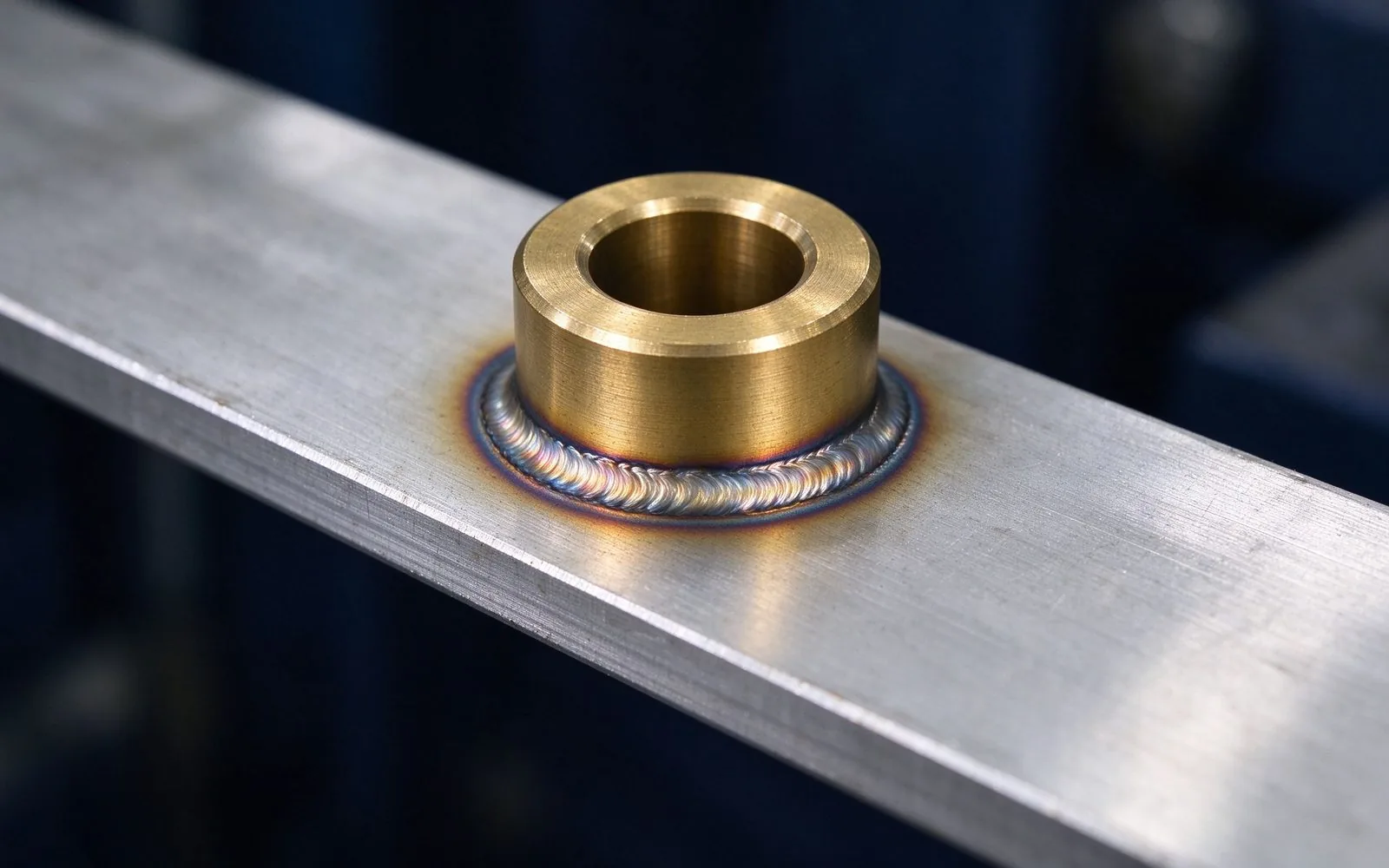
Bolted joints are the workhorse of distribution and serviceable assemblies. The three enemies are torque relaxation (bolt creep plus thermal cycling), plating wear (fretting of tin or silver under micromotion) and galvanic pairing between dissimilar metals. M6 and M8 studs on busbars are standard; the specification question is plating thickness, washer/lock features and re-torque intervals.
The terminal connection guide covers the practical side; the engineering rule is that contact area, plating and clamp force must be designed together, then locked by test.
Copper, dielectric, module baseplate and terminals all expand at different rates, so the interface sees a mechanical strain cycle with every thermal cycle. Over tens of thousands of cycles, that strain migrates to the weakest link: weld toes, solder joints, or the contact surface under a bolt head.
Design levers: match effective CTE with the stack-up, use compliant layers (flexible tabs or spring elements) where strain concentrates, and validate with thermal-cycling testing that covers the real operating band — the test profile is the contract.
The switching loop runs module-to-busbar-to-capacitor, and its inductance sets the overshoot and losses at every switching event. At the interface, inductance is shaped by geometry: current in the two polarities running close and parallel, terminals kept short, and the busbar's laminated layers bringing the return path adjacent to the forward path.
That is why laminated construction wins at the module: the low-inductance layout is a property of the busbar, not an afterthought. Design targets of a few nH for the module loop are achievable with a properly layered busbar.
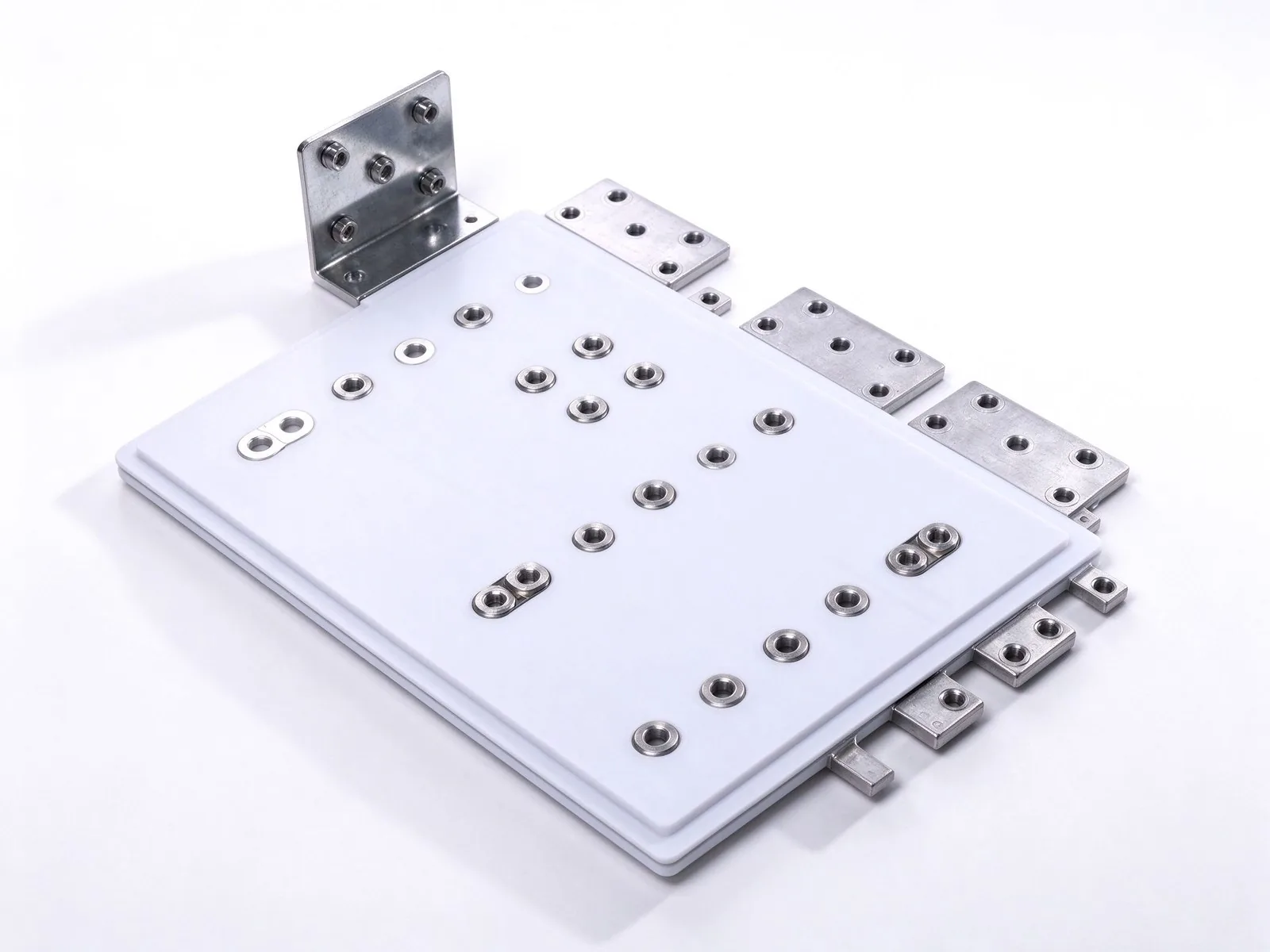
Converters parallel modules to reach the current class; unequal sharing then overloads one module while its neighbor idles. The busbar decides sharing through its resistance and inductance symmetry: equal path lengths, symmetric feed points and mirrored geometry keep currents balanced across modules.
The failure mode is subtle — a sharing imbalance that looks fine at DC but skews under fast transients. The current sharing design guide details the layout rules and the measurements that catch it before the field does.
Module terminal spacing is set by the device package, and the busbar must respect creepage and clearance distances around those terminals at the operating voltage and pollution degree. At high-voltage DC this is where the busbar's dielectric edge treatment and the module's footprint interact.
Ask the supplier for the creepage/clearance calculation over the actual interface geometry — the gap between module pins and the busbar edge is the classic spot where a clean-looking design fails hipot.
Each connection family needs its own inspection gate. Pressed: force or deflection check plus plating wear sample. Welded: pull or shear sampling with documented frequency and limits. Bolted: torque and angle audit, plus re-torque verification after thermal cycles. Add electrical gates — contact resistance and temperature rise at rated current — and the interface becomes measurable instead of hoped-for.
SHANYUAN's quality system runs these gates per lot and keeps the records with the batch trace.
Confirm the connection family against duty and serviceability; state module terminal pitch, material and plating; define the current and its transient profile; set the operating temperature band and cycling count; give the enclosure's pollution degree and altitude; and specify the inspection and test evidence you expect with each lot.
With those inputs, the custom busbar design route returns a drawing, a DFM review and test definitions in one pass — the checklist is the RFQ.
SHANYUAN builds the module-side hardware itself: C11000 copper laminated busbars in 1–6+ layers with PET/Nomex/DLF dielectrics, M6/M8 stud, blade or welded terminals, tin-plated contacts, ~1000 A class, plus in-house welding with pull-test records. The 17,200 m² Rizhao facility exports to 20+ countries.
Engineering review and quotation take one business day via the contact page — send the drawing and the checklist together.
A busbar connection is only as good as its joint. Ultrasonic welds reach 0.005-0.169 mOhm
Read article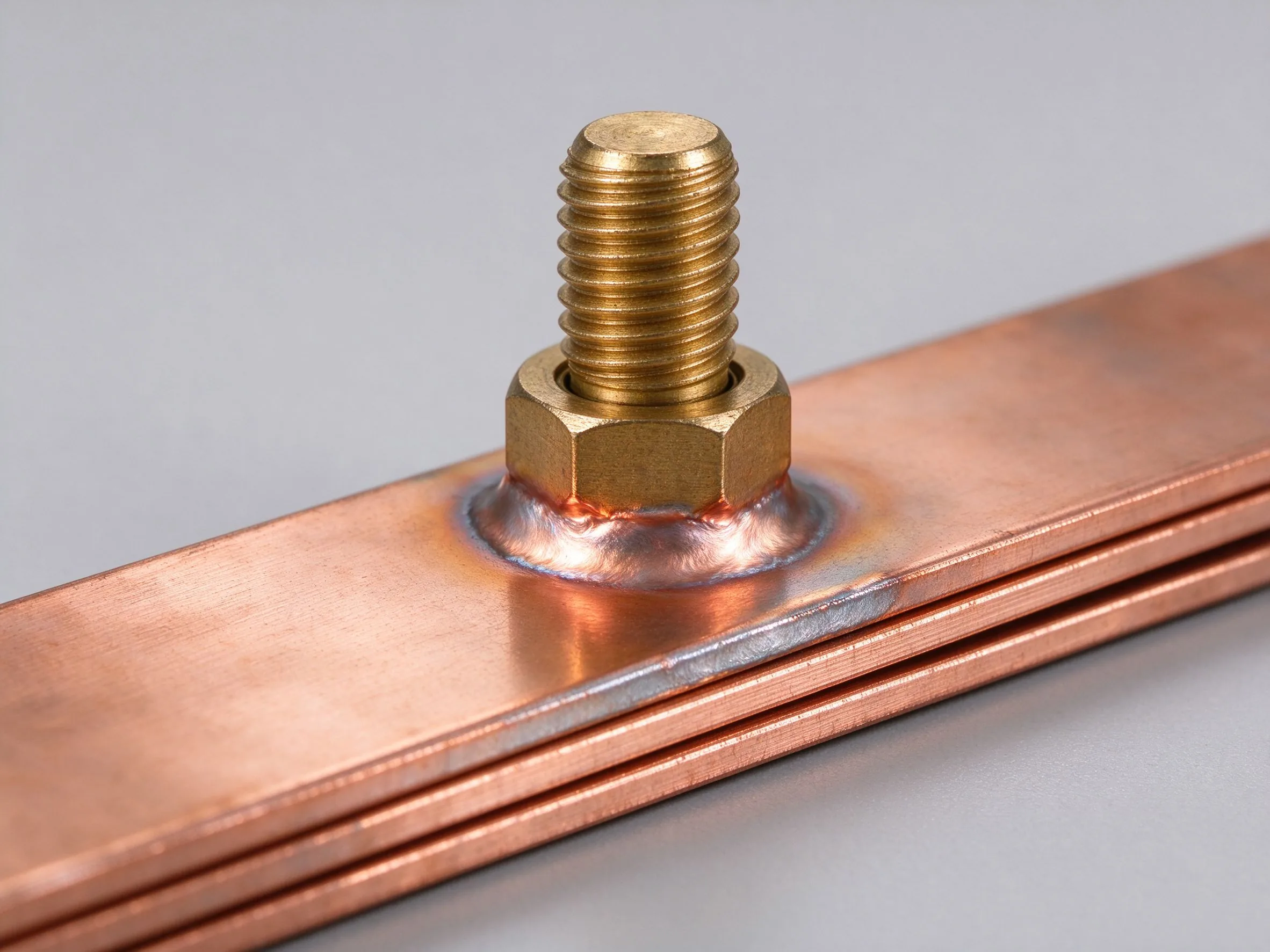
The terminal is where most busbar field failures happen, and the choice is usually made to
Read article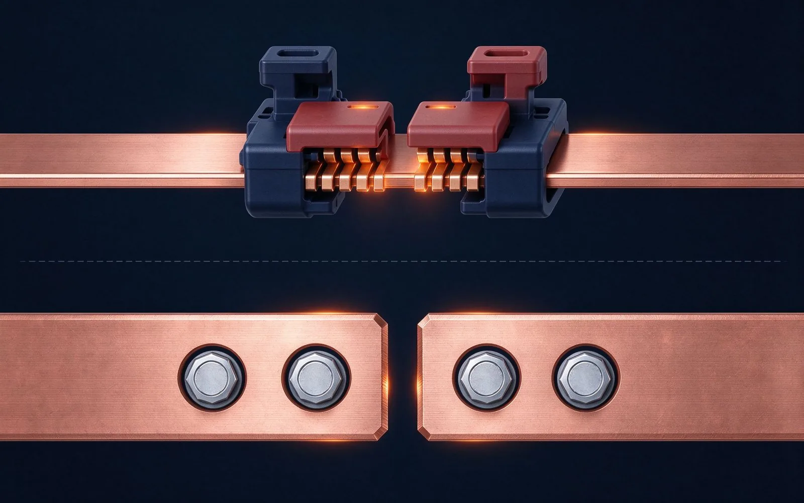
Parallel busbars are supposed to share current equally — physics disagrees. Skin effect pu
Read article
Thomas O'Brien is a manufacturing process engineer with 14 years in stamping, lamination and terminal machining for laminated busbars. He manages production lines for precision-cut profiles, insulation layering and CNC terminal processing, and focuses on dimensional control and repeatability at
Send the current profile, voltage class and terminal types — our engineers reply within one business day.