Airborne and defense programs budget weight, envelope and survival the way terrestrial systems budget cost. We engineer low-profile laminated aerospace busbars that fit non-rectangular mechanical envelopes, stay PD-controlled at altitude and stay de-rated for decades of service.
The four places busbars carry current in this application.
Low-profile laminated distribution inside airborne power distribution units, feeding multiple load busses from one feed in a single insulated, form-fitting assembly that replaces hand-built harnessing.
The low-inductance laminated spine between onboard DC sources, DC-link capacitors and the power stage of airborne converters, inverters and motor drives used in flight and ground support.
Form-fitting, rotation-capable bars in mechanically hostile locations such as rotating blade-hub electronics, where the bar must survive continuous rotation, vibration and shock.
De-rated, long-life distribution bars inside vehicle-mounted and ground-based military platforms, where service continuity under field conditions and extended shelf life is mandatory.
Ruggedized bars routing bulk DC between rectifiers, capacitor banks and transmit-stage power supplies in ground-station, radar and ground-support equipment.
Minimal-weight, low-profile links between the battery bus and flight-control, propulsion and payload electronics in unmanned aircraft, where every gram is a payload trade-off.
Tell us the platform voltage and DC-link voltage, the continuous and peak current per circuit, and the derating factor your program requires. Dielectric selection, creepage and clearance, and conductor cross-section all follow from these inputs — airborne designs typically run at a derated fraction of the conductor's reference ampacity rather than at its limit, which is how long service life is engineered in. Where the bar interfaces higher-voltage protection, we apply the same partial-discharge discipline we document in our notes on <a href="/resources/partial-discharge/">partial discharge in busbars</a>.
Share the mechanical envelope, the available height budget, and any rotation, sweep or vibration axis the bar must live with. The reference aerospace design we work through is a low-profile bar shaped as a pentagon rotating about its center: power enters through a center hole from a circular connector and flexible cables, then distributes to edge-mounted PCBs. That envelope-first, non-rectangular geometry is the form factor we design against — the same design-thinking we lay out in our <a href="/resources/design-guide/">laminated busbar design guide</a>.
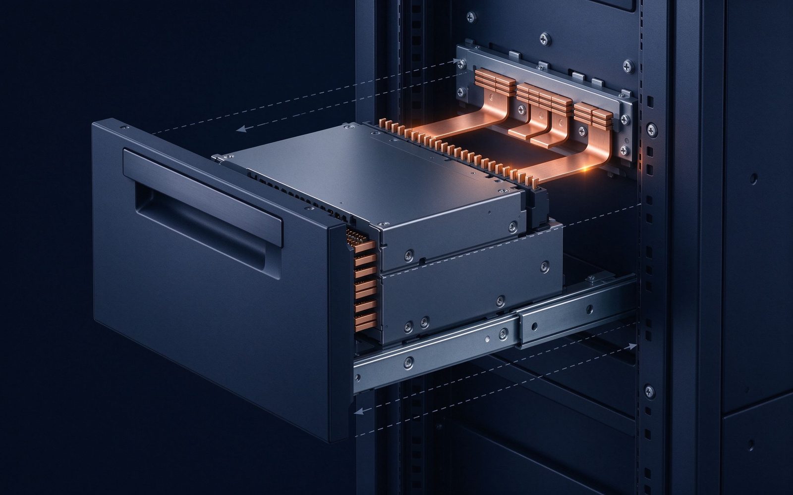
Provide your vibration spectrum, shock pulse and operating/storage temperature range. These drive the choice between rigid laminated sections, flexible lamella joints, and press-fit multi-point contact interfaces that avoid threaded hardware at the joint face — the loosening paths that vibration opens up. Flexible laminated profiles absorb vibration and differential thermal expansion exactly where rigid bars would transfer stress into terminals; we cover their design rules in our notes on <a href="/resources/flexible-busbars/">flexible busbars</a>.
State the maximum operating altitude and the partial-discharge acceptance level your program requires; we verify PD below the ~10 pC industry reference at elevated test voltage. Thin air at altitude lowers PD inception voltage, so sealed edges, controlled layer alignment and gap control are designed in from the first layout. Read the physics in our notes on <a href="/resources/partial-discharge/">partial discharge in busbars</a>, and tell us your test voltage at quotation.
Tell us what your quality system requires: lot-level traceability of conductor and dielectric materials, batch test records (hipot, insulation resistance, dimensional, continuity), CoC or PPAP-style documentation. Conductor, insulation and plating options can be specified to aerospace-industry requirements; we align our documentation package to your audit expectations. RoHS / REACH environmental compliance is our product baseline, and documentation supports UL / CSA-style component recognition where your program requires it.
Defense, military and security programs demand the highest levels of reliability, quality and performance, and airborne power distribution sits at the strictest end of that requirement. A flight vehicle budgets weight, envelope and cooling the way terrestrial equipment budgets cost — every gram of copper, every millimeter of height, every degree of temperature rise competes with fuel, structure and avionics. Where a rail traction busbar faces the ground vibration of a locomotive, an airborne bar faces rotation, low-pressure altitude and a weight budget that penalizes every added component. The laminated busbar that distributes power inside an aircraft, helicopter or defense platform is therefore engineered as much for geometry and survival as it is for current.
The reference aerospace case illustrates the envelope problem directly. A compact power-distribution unit had to rotate about its center inside mechanically hostile equipment — electronics carried on a rotating assembly. The solution was a low-profile laminated bar shaped as a pentagon, rotating with the assembly: power enters through a center hole from a circular connector and flexible cables, lands on the bar's center pads, and the laminated plane distributes it outward to PCBs mounted at each of the five edges. A rectangle could not fit that envelope; the laminated stack could be stamped, laminated and edge-sealed into the non-rectangular geometry in one thin insulated plane. That is the core value of laminated construction in aerospace: the distribution layer becomes a single, form-fitting part instead of a harness assembled by hand, and it can follow a mechanical envelope that no rectangular bar would reach. We build these as 1–6+ layer C11000 copper assemblies, part of our power electronics busbars family, with conductor sections derated to your flight envelope rather than sized to a nameplate peak.
Material and interface selection follows the environment. The conductor is copper (C11000 reference; aluminum on request); dielectric options span polyester film, Nomex paper and epoxy systems chosen for temperature class and humidity; plating is selected per joint behavior — tin as the standard finish, nickel where corrosion protection leads, silver or gold where the contact sees repeated insertion, minimal voltage drop or aggressive corrosion. At the interface, blind-mate and float-mount contacts absorb positional tolerance, and press-fit multi-point contact geometry replaces threaded hardware at the busbar face: reference contact frames carry 175–265 A at a 30 °C rise (up to ~365 A bus-terminated) through many parallel contact junctions rather than one high-normal-force bolt — which is exactly what keeps a joint reliable under sustained vibration. Where differential motion exists, flexible lamella sections or flexible laminated jumpers absorb the stress, the same vibration-absorption design rules we describe in our notes on flexible busbars. Materials, insulation and plating options can be specified to aerospace-industry requirements, and our documentation — batch test records, CoC and lot traceability — aligns to your quality system rather than asking your team to adapt to ours.
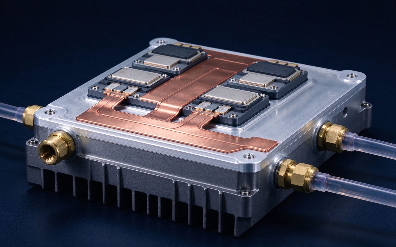
Altitude adds the second design axis. Thin air lowers the dielectric strength of the gaps around and within the bar, which lowers the partial-discharge inception voltage; a design that passes PD tests on the ground can discharge in service at altitude. Sealed edges, controlled layer alignment and tight interface gaps keep partial discharge below the industry reference of ~10 pC, verified at test voltage above operating — the PD discipline we explain in our notes on partial discharge in busbars, and the same sub-10 pC expectation that compact high-voltage protection designs set for themselves. Where the airborne stage carries more than ~200 A in a confined volume, conductor cross-section alone is no longer the thermal answer: we co-design the bar with extruded heatsinks for forced air or liquid-cooled cold plates for the densest stages, the integrated thermal practice we cover in our notes on busbar thermal management. Across aircraft distribution units, airborne converter DC links, military platform distribution, satellite ground stations and UAV power links, the engineering pattern is the same — de-rated, documented, envelope-first. Send us the mechanical envelope and the voltage/current budget for a DFM review; we reply within one business day, the same process we run on every custom busbar program.
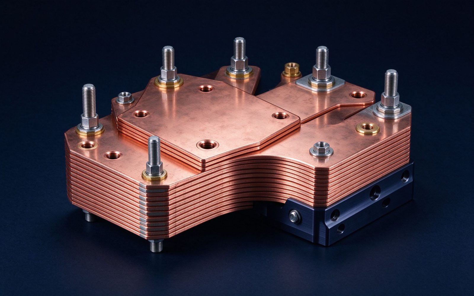
The part this application is built around — a SHANYUAN laminated busbar, factory direct.
Reference photographs from SHANYUAN production and shipped assemblies.
Selected notes and product pages that back the design choices on this page.
From spec review to shipped, tested parts — one accountable supplier.
| Material | Standard options |
|---|---|
| Conductors | C11000 copper as standard; aluminum available on request |
| Dielectrics | PET, Nomex and epoxy (DLF) films, selected by voltage class and operating temperature |
| Plating | Tin finish for corrosion protection and joint solderability |
Voltage class, current profile and terminal types — we will share reference configurations and DFM guidance.
Straight answers from the engineering team.
Send the application, voltage class and current profile — we will share reference configurations and DFM guidance.
Send drawings, current ratings and voltage class — DFM feedback and a quotation within one business day.
