DC fast chargers push high-voltage DC from the rectifier to the vehicle connector with minimal loss. Our EV charging station busbars carry that bulk DC compactly, with low inductance and partial-discharge control at fast-charge voltage levels.
The four places busbars carry current in this application.
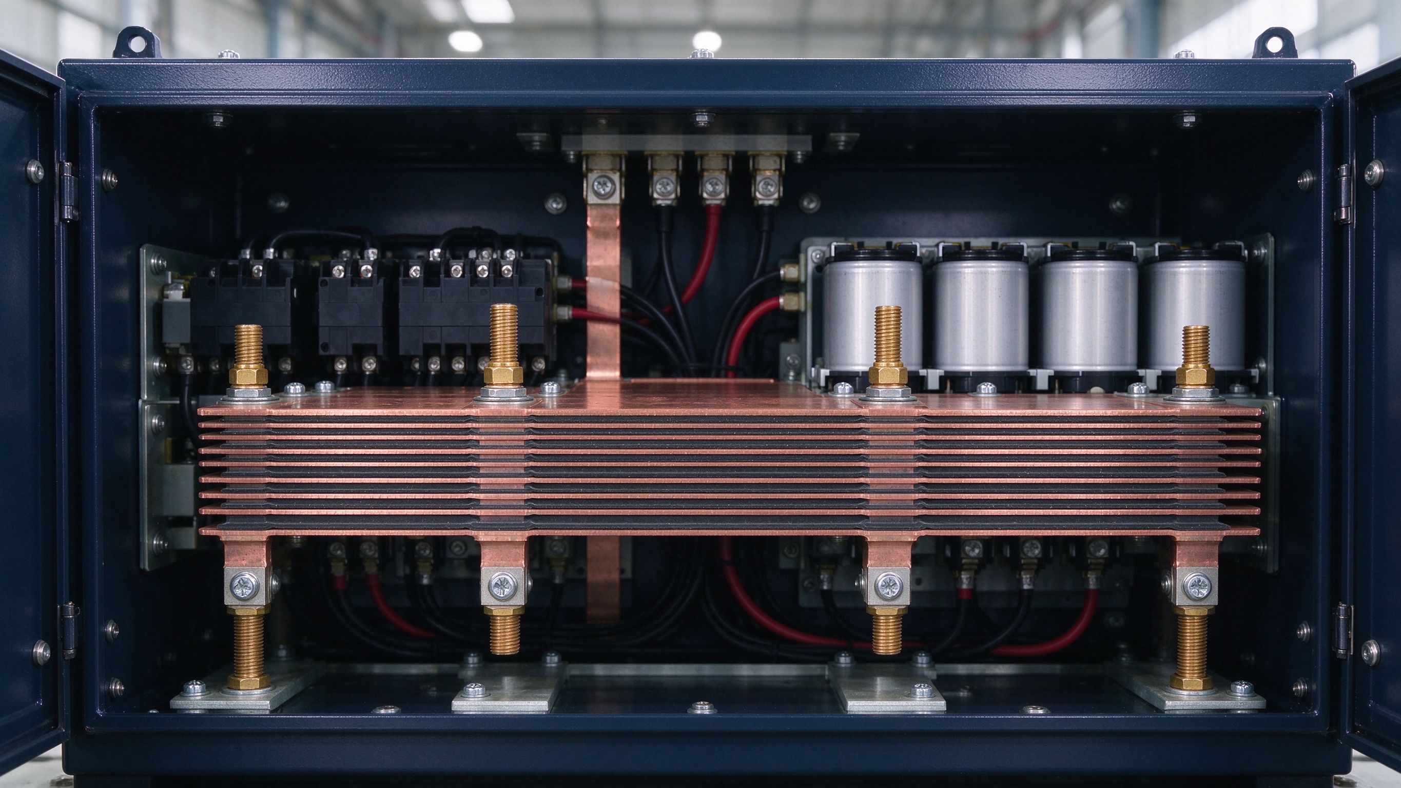
The laminated backbone between the rectifier output and the DC-link capacitor bank inside the power cabinet.
Compact multilayer bars distributing bulk DC from the DC link to each parallel charging module.
Short, low-inductance paths from the DC bus through output filtering to the charging outlet interface.
Matched, symmetric busbar sets letting parallel power modules share current evenly.
Compact connections for precharge resistors, contactors and bleeder paths in the power cabinet.
Integrated studs and connectors on the busbar providing an all-in-one transition to the charging cable harness.
400 V, 800 V or a higher fast-charge architecture — dielectric and creepage follow from this.
Unit power and the number of parallel modules set current sharing and conductor sizing.
Outlet connector types and cable harness interface — integrated studs or connectors designed to match.
Ambient range, humidity, and any salt or UV exposure for roadside installations.
Which joints must be field-serviceable — bolted studs versus welded tabs, decided at DFM.
EV adoption drives roadside fast-charging build-out, and every charging cabinet is a power-conversion station in its own right. The laminated busbar is a key element in the station's power-distribution circuitry: it transfers electricity from the source to the input connector of the charging circuit. Faster charging requires higher voltages, and higher-voltage charging depends on a robust DC link and power-distribution system that the busbar must support.
Inside the cabinet, the laminated busbar forms the DC-link and distribution backbone of the EVSE power stage — carrying the bulk DC from the rectifier to the outlet connector with low loss. Reference designs pair standard laminated bars with compact powder-coated construction where the envelope is smallest; the compact grade trades some voltage headroom (reference up to 2.5 kV AC) for geometry that film lamination cannot cover, and resists harsh roadside conditions including oil and salt. Where charging modules sit in parallel, matched and symmetric busbar sets share current evenly across every module.
At DC-fast-charge voltage levels, the design center shifts to isolation and partial discharge. Optimizing for high-voltage isolation and PD control — sealed edges, no trapped air gaps, verified below the industry reference level of 10 pC — protects the DC-link capacitors and semiconductor switches that charging revenue depends on. Low inductance is the same discipline we apply to EV traction inverters: shorter commutation loops mean lower overshoot (V = L × di/dt), longer capacitor life and cooler operation in sealed cabinets.
Roadside equipment also has to be serviceable without a full teardown. Tooled bolted studs and integrated cable transitions replace hours of hand-built harnessing, eliminate wiring errors, and give maintenance a defined disconnect point. On the vehicle side, our battery busbars family covers module and pack links; on the cabinet side, the power electronics family covers the DC link. Send us the charger voltage and module layout — DFM feedback within one business day.
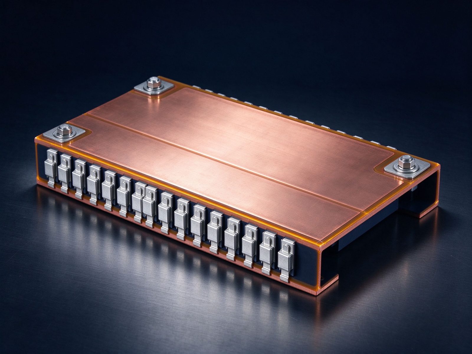
The part this application is built around — a SHANYUAN laminated busbar, factory direct.
Reference photographs from SHANYUAN production and shipped assemblies.
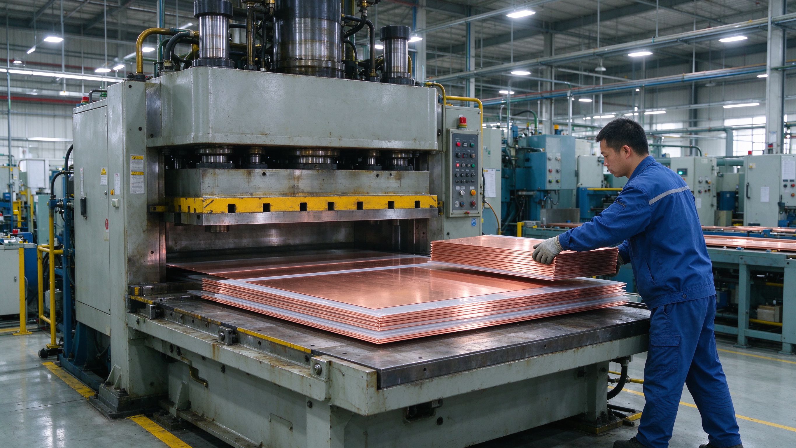
Selected notes and product pages that back the design choices on this page.
From spec review to shipped, tested parts — one accountable supplier.
| Material | Standard options |
|---|---|
| Conductors | C11000 copper as standard; aluminum available on request |
| Dielectrics | PET, Nomex and epoxy (DLF) films, selected by voltage class and operating temperature |
| Plating | Tin finish for corrosion protection and joint solderability |
Voltage class, current profile and terminal types — we will share reference configurations and DFM guidance.
Straight answers from the engineering team.
Send the application, voltage class and current profile — we will share reference configurations and DFM guidance.
Send drawings, current ratings and voltage class — DFM feedback and a quotation within one business day.
