Every laminated busbar ends in a termination, and that interface — not the copper — is where resistance grows, heat builds and vibration finds a weak point. This guide gives purchasing managers and engineers a repeatable way to choose between M6/M8 studs, blade contacts, welded joints and crimped connections.
Every laminated busbar ends in a termination, and that interface — not the copper — is where resistance grows, heat builds and vibration finds a weak point. This guide gives purchasing managers and engineers a repeatable way to choose between M6/M8 studs, blade contacts, welded joints and crimped connections.
A busbar can be perfectly laminated, perfectly tested, and still fail in service at a poorly designed termination. The reasons are mechanical and thermal. Bolted joints relax under thermal cycling unless the hardware and torque are right; welded joints crack if the base metal or process is wrong; blade contacts fret and oxidise in vibration; crimps depend entirely on tooling quality.
Every one of these modes is preventable, but only if the termination type is chosen against the actual duty — current, temperature cycle count, vibration spectrum, maintenance access — instead of habit. The rest of this guide is that selection process, and the terminal connection guide covers the joint-design detail behind it.
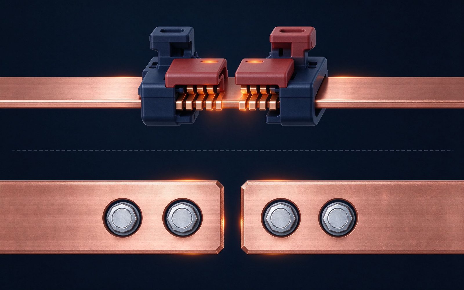
Terminal current rating is a contact-resistance story, not a copper cross-section story. A bolted M8 stud with a proper Belleville washer and controlled torque on tin-plated surfaces holds contact resistance in the micro-ohm range; a loose or corroded joint can double that within a year and drive local temperature rise past the dielectric limit.
For high-current duty (600-2500 A class), surface preparation is the differentiator: tin plating on both mating faces, flatness within the joint footprint, and plating thickness consistent with UL 467 guidance on grounding and bonding hardware. The plating and corrosion guide covers the coating side; the practical rule is that a termination spec should state plating, flatness and torque together, not just the stud size.
Vibration is the most common reason a stud termination fails and a welded one wins. In a substation, a switchgear cubicle, or a vehicle-mounted battery pack, sinusoidal and shock loads loosen conventional nuts over thousands of cycles. The bolted-joint vibration design note lists the countermeasures: serrated flange nuts, lock washers, thread-locking compound, and — the real fix — joint designs that put the shear plane through the clamped faces rather than through the fastener shank.
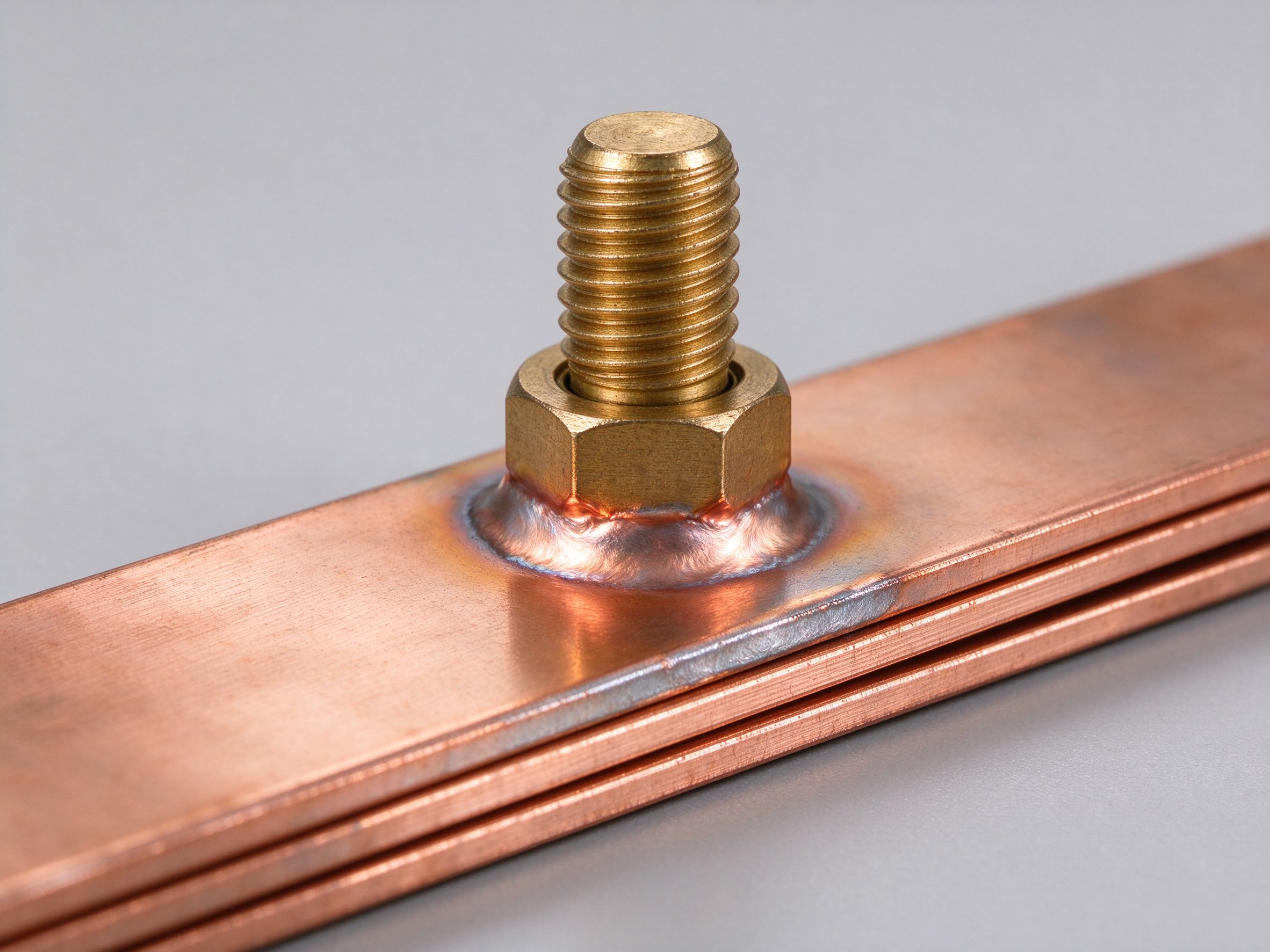
When the vibration spectrum is severe and maintenance access is poor, welded or crimped terminations are the robust answer, which is why cell-to-busbar fusion inside EV and ESS modules is almost universally welded today.
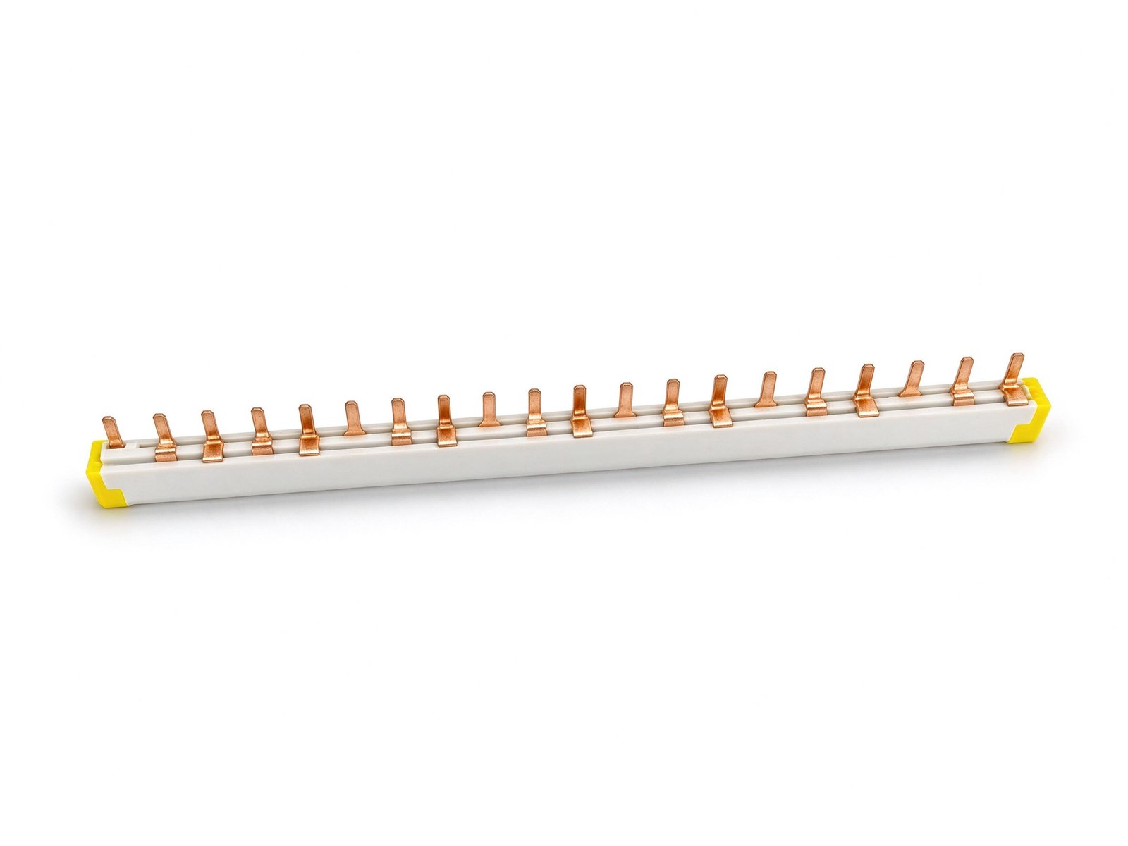
| Attribute | M6/M8 stud | Blade contact | Welded | Crimped/pressed |
|---|---|---|---|---|
| Serviceability | Yes — removable | Yes — plug/unplug | No — permanent | No — permanent |
| Vibration tolerance | Good with hardware | Good with retention | Excellent | Excellent |
| Contact resistance control | Torque + plating | Spring force + plating | Metallurgic bond | Die set + verification |
| Thermal cycling | Needs re-torque plan | Good | Excellent | Good |
| Field assembly | Yes | Tool-less | No | Special tooling |
| Typical duty | Substation, switchgear, cable links | Rack/drawer/module plugs | Cell fusion, module links | Cable-to-bar transitions |
| Cost per joint | Low-medium | Medium | Medium-high | Low-medium |
Ratings are relative planning values; the current-rating and test basis follow UL 467 and IEC 61439-1 joint test practice.
Thermal cycling is where bolted joints quietly fail. Copper expands about 17 ppm/°C; every power cycle moves the joint faces microscopically, and over 10,000 cycles the surface oxide film grows unless the plating and pressure are correct. A joint designed for 30°C rise at rated current with proper plating survives; an under-plated or under-torqued joint does not.
The thermal-cycling reliability guide explains the test cycles and acceptance criteria. For procurement, the shortcut is to require the fabricator's test evidence on the specific termination — a resistance-vs-cycles curve, not just a catalogue number.
Most production busbars carry more than one termination family. A typical power electronics busbar has M8 studs where the DC cables land, blade contacts where the module plugs in, and weld pads for the internal capacitor links. Mixed families are fine — the discipline is that each interface is engineered against its own duty and documented with its own torque/insertion/weld schedule.
This is also where a single fabricator earns its keep: stamping, plating, stud welding, blade forming and weld-pad preparation in one plant means the interface schedules are consistent and the test report covers the whole assembly rather than parts. The custom busbar engineering process on this site starts from exactly this mixed-interface drawing.
Send these fields with every busbar RFQ so the termination can be engineered rather than guessed:
SHANYUAN quotes M6/M8 stud, blade, welded and crimped terminations on tin-plated C11000 copper and ships the joint test reports with the assembly — the same evidence North American buyers are now demanding as tariffs and lead times tighten, as our reshoring article explains.
Choose the termination against the duty, not the habit: studs for serviceable power joints with torque control, blades for break/remake interfaces, welds for sealed high-integrity links, crimps for cable transitions — and verify each with measured contact resistance and thermal-cycle evidence. If the duty is a grid project with long lead times, pair the decision with the European grid spending picture; if it is a tropical ESS or data center build, the Southeast Asia market article shows the ambient conditions that stress joints hardest.
Still unsure? Send the circuit, current and vibration environment and we will recommend the termination mix with the supporting test data.
Field returns are the best teacher in termination design, and the pattern is consistent across applications. The first category is bolted-joint overheating from torque drift: the joint was assembled correctly, then thermal cycling relaxed it, and nobody re-torqued. The second is blade-contact fretting in vibration: the plating wore, the contact resistance rose, and the drawer started tripping intermittently. The third is weld quality: a bad fusion passes a static pull test but fails under thermal cycling.
Each failure maps to a prevention. Torque drift is prevented by locking hardware and a documented re-torque interval — the maintenance guide has the interval table. Blade fretting is prevented by plating selection and spring-force verification, covered in the plating guide. Weld defects are prevented by process qualification and sample cross-sectioning, described in the welding guide.
For buyers, the practical habit is to ask the supplier for its field-return statistics and root-cause notes on terminations. A fabricator that tracks failure modes — rather than one that says "we have never had a problem" — is the one whose next design will survive the duty. That evidence culture is part of the quality system SHANYUAN applies to every terminal on every assembly.
The terminal is where a laminated busbar meets the outside world. This guide covers M6/M8
Read article
A bolted busbar joint fails in one of two ways: vibration loosens it or thermal cycling fa
Read article
Thomas O'Brien is a manufacturing process engineer with 14 years in stamping, lamination and terminal machining for laminated busbars. He manages production lines for precision-cut profiles, insulation layering and CNC terminal processing, and focuses on dimensional control and repeatability at
Send the current profile, voltage class and terminal types — our engineers reply within one business day.