Mon–Fri 9:00–18:00 · CST (UTC+8) · Shandong, China
Application · Renewable Energy

Solar & Wind Inverter Busbar Solutions

PV inverters and wind converters convert variable DC into grid-grade AC — and next-generation designs switch faster and run up to 1600 VDC. Our solar inverter busbars keep the DC link low-inductance, insulated and PD-controlled.

Where They Are Used

In the Renewable Energy

The four places busbars carry current in this application.

PV String DC Collection

Form-fitting laminates collecting DC from string combiners into the inverter DC input.

DC-Link between Capacitors and IGBTs

The low-inductance spine connecting the DC-link capacitor bank to the IGBT/MOSFET bridge.

Wind Converter Stage Links

High-current connections between the generator-side rectifier and the grid-side converter in turbine nacelles.

Brake Chopper and Dump Load Links

Pulsed-duty bars feeding crowbar circuits and dump resistors during grid faults.

Precharge and Bleeder Resistor Links

Compact low-inductance paths for precharge resistors and discharge circuits inside the cabinet.

Gate-Drive Integration

Hybrid power+signal layouts routing driver signals alongside the power plane for compact inverter stages.
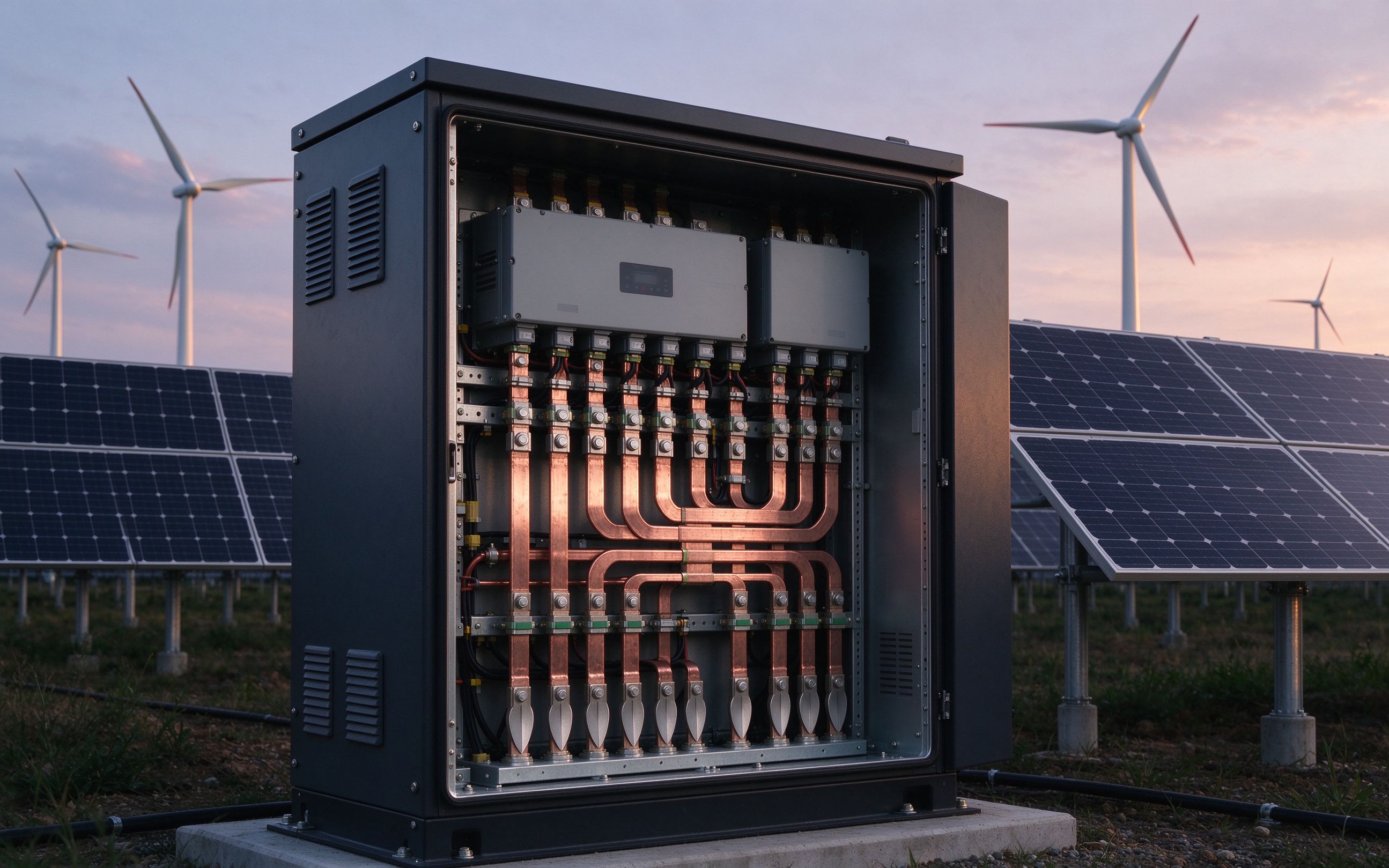
Design Priorities

Why laminated wins here

  • PD control at 1600 VDC — Reference next-generation converter designs operate up to 1600 VDC bus voltage, which raises requirements on isolation, creepage/clearance and partial-discharge control.
  • Low inductance for faster switches — Multilevel topologies switch faster; tight commutation loops protect IGBT and SiC devices from overshoot, V = L × di/dt.
  • Humidity and salt robustness — PV inverters run essentially continuously, so reliability over a 25-year reference service life in varying humidity and offshore salt exposure matters more than power-cycling tolerance.
  • Thermal margin where cooling shrinks — High-temperature dielectric options rated up to 130 °C continuous let more current pass through the same copper cross-section as cooling margins tighten.
  • Low-loss continuous duty — Low-resistance laminated paths minimize heat in cabinets that must run with minimal downtime — from residential kW to multi-MW stations.
Laminated busbar connecting DC-link capacitors to the IGBT stack inside a solar inverter cabinet
Engineering Notes

Tell us these at quotation

DC bus voltage

1000 V or 1500 V (1600 VDC reference) — dielectric, creepage and clearance are set by this.

Power range and duty

Residential, commercial or utility scale, and continuous versus cycling duty — it shapes derating choices.

Environment

Outdoor, containerized or offshore: humidity class, salt exposure and ambient range, at quotation.

Capacitor and module layout

Capacitor positions and IGBT module datasheet pitch define the lowest-inductance commutation loop.

Cooling concept

Natural convection or forced air — conductor sizing follows the thermal design.

Application Deep-Dive

Solar & Wind Inverter Busbar Solutions

In wind turbines and solar farms, power semiconductors convert variable-voltage inputs into fixed-voltage outputs for grid connection. A solar inverter converts the variable DC of a PV array into utility-frequency AC — it is the key, often most expensive, component of the system, and it is growing more complex as semiconductors deliver faster switching and higher power density. Power ranges from a few kilowatts in residential units into the megawatt range at utility scale.

The laminated busbar is the connection between the DC source, the DC-link capacitors, resistors, drive circuitry and the IGBT/MOSFET modules — the low-inductance spine of each inverter stage. Next-generation converters use multilevel switching topologies with faster switches and operating voltages up to 1600 VDC, demanding improvements throughout the conversion chain. That voltage climb raises the bar on isolation, creepage/clearance and partial discharge: trapped air bubbles at insulation interfaces are a root cause of PD, and continuous discharge above the industry reference level of 10 pC degrades insulation over time. We cover the physics in our notes on low-inductance busbar design.

Environment is the other half of the design. PV inverters run essentially continuously, so high humidity robustness and low lifetime cost matter more than power-cycling tolerance; wind converters in nacelles face varying temperatures, humidity and salt exposure offshore. Where cooling margins shrink — concentrated PV dense arrays especially — designs lean on high-temperature dielectric systems rated up to 130 °C continuous versus 105 °C standard, pushing more power through the same copper section. Thermal management remains the key reliability lever, which is why we size conductors against the actual cooling concept rather than nameplate current alone.

Across the power electronics busbars family, the same discipline applies: sealed edges, no trapped air gaps, and terminals matched to module pin pitch. The ampacity chart gives the reference starting points for copper cross-sections — before derating for your enclosure. Tell us your DC bus voltage and power range at quotation and we will come back with DFM feedback, usually within one business day.
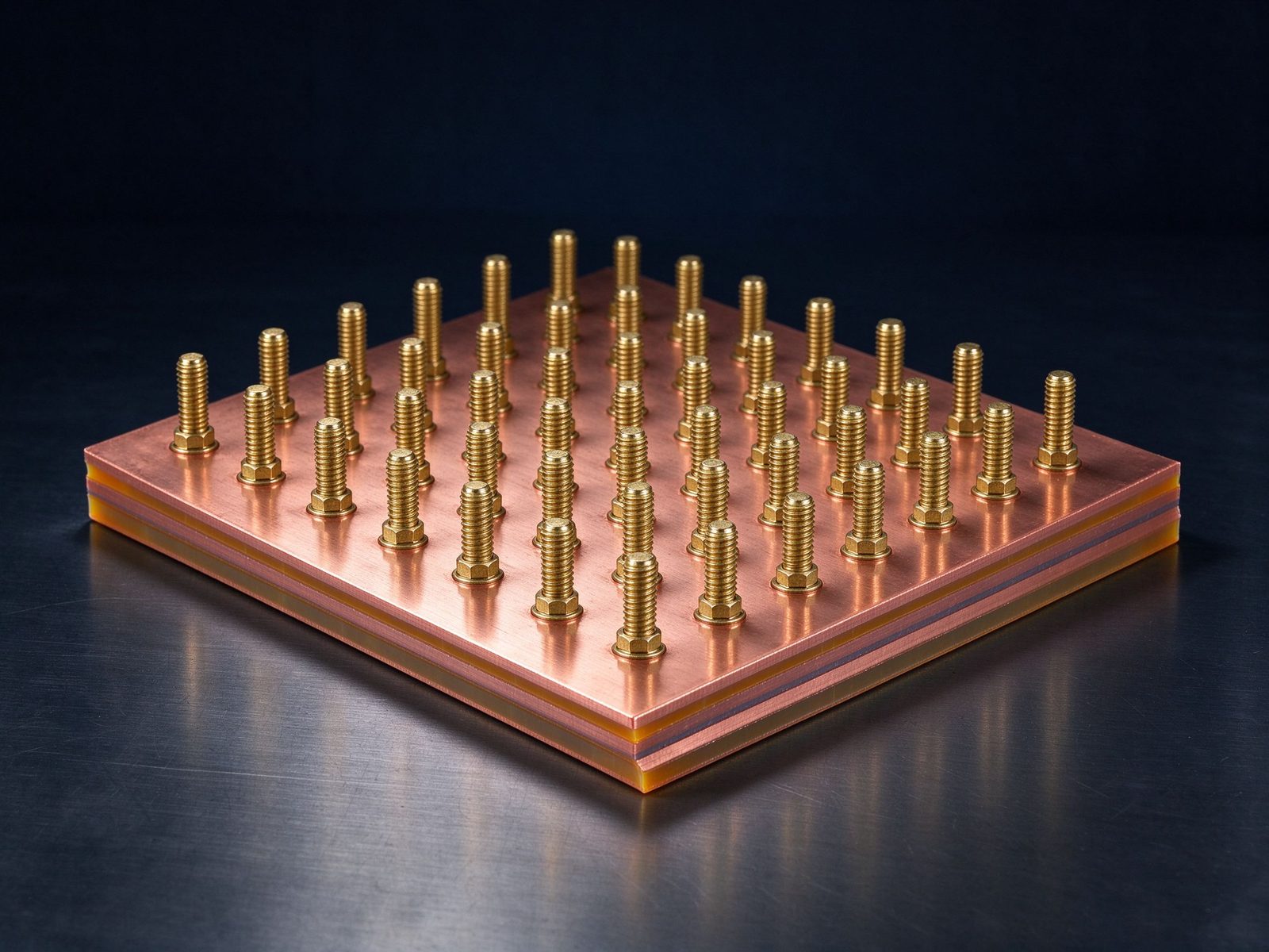
SHANYUAN renewable energy laminated busbar assembly

The part this application is built around — a SHANYUAN laminated busbar, factory direct.

On the Floor

This application in production

Reference photographs from SHANYUAN production and shipped assemblies.
Renewable energy inverter station with laminated DC links
Solar and storage inverter stations built on low-inductance DC links.
Power electronics laminated busbar for renewable converters
Power electronics laminate carrying converter phase outputs.
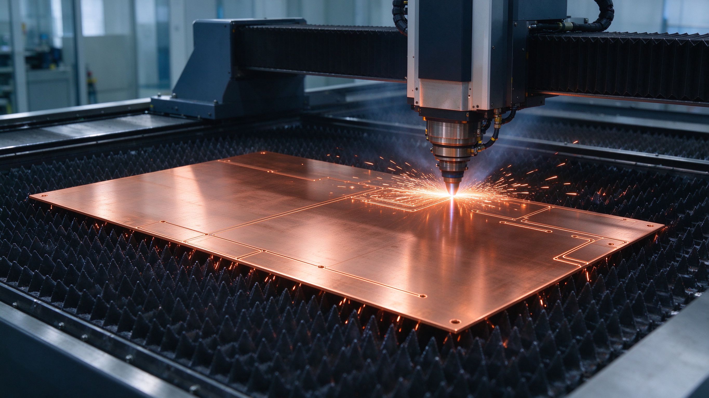
Laser cutting copper conductor profiles at SHANYUAN
Laser-cut conductor profiles — tooling fixed at DFM review.
Related Reading

Go deeper on the engineering

Selected notes and product pages that back the design choices on this page.

13+Years since 2012
1–6+Conductor layers
~1000 ACurrent rating
1 dayTechnical response
Project Flow

How a custom project runs

From spec review to shipped, tested parts — one accountable supplier.

Spec ReviewDrawing, current rating, layers and terminals confirmed with you
DFM ReviewEdge distances, weld zones and clearances checked before tooling
QuotationTechnical and commercial quote within one business day
Sample BuildPrototypes for fit and electrical verification
Tooled ProductionControlled process with documented QC per lot
DeliveryPacked to your requirements, test records on request
Incoming Materials

What goes into the stack

MaterialStandard options
ConductorsC11000 copper as standard; aluminum available on request
DielectricsPET, Nomex and epoxy (DLF) films, selected by voltage class and operating temperature
PlatingTin finish for corrosion protection and joint solderability
Engineering Resources

Go deeper

Laminated Busbar Design Guide

Construction, dielectric selection and current capacity basics.

Read

Busbar Ampacity Chart

Copper current ratings with derating guidance.

View

Busbar vs Cable

Where laminated wins — and where it does not.

Compare

One technology, every application.

Voltage class, current profile and terminal types — we will share reference configurations and DFM guidance.

FAQ

Frequently asked questions

Straight answers from the engineering team.

What are the standard conductor and dielectric options?
Conductors are C11000 copper as standard, with aluminum available on request, tin plated. Dielectrics include PET, Nomex and epoxy (DLF) films, selected according to your voltage class and operating temperature.
What testing is performed on production lots?
Testing follows the specification agreed at design freeze: dielectric withstand (hipot), insulation resistance, dimensional inspection, visual inspection of plating and edge sealing, and continuity checks per conductor path.
What current ratings can SHANYUAN busbars handle?
Rating is designed per application up to roughly 1000 A, sized against continuous and peak current with thermal margin — see our ampacity chart for the starting reference points.
How long does a sample build take?
A sample is typically produced within 5–7 working days from drawing approval. Fit and electrical verification is done in-house, and you receive test results together with the sample.
What quality system do you follow?
Production follows a documented process chain with batch records: incoming material checks, dimensional inspection, hipot and insulation testing, continuity checks and final visual inspection. Test records are issued per lot on request.
Do you support international shipping and packaging?
Yes. Parts are packed with edge protection, anti-static film and export-grade cartons to your handling requirements, and shipped by sea or air. Commercial documents (invoice, packing list, test records) are provided with every shipment.

Solar & Wind Inverter Busbar Solutions

Send the application, voltage class and current profile — we will share reference configurations and DFM guidance.

Talk to our engineering team

Send drawings, current ratings and voltage class — DFM feedback and a quotation within one business day.

Send an InquiryWhatsApp