"What current can your busbar carry?" is the most common question we get from engineers starting a new inverter, battery pack or PCS design. The honest answer is: it depends on the copper cross-section, the allowed temperature rise, the ambient, how the part is mounted, and whether it sits next to other heat sources. At SHANYUAN we specify laminated busbars on a 30 °C temperature-rise reference in free air at 40 °C ambient, horizontal mounting — and then we apply derating factors for the real installation. This article walks through that method so you can size a copper busbar current rating correctly the first time.
"What current can your busbar carry?" is the most common question we get from engineers starting a new inverter, battery pack or PCS design. The honest answer is: it depends on the copper cross-section, the allowed temperature rise, the ambient, how the part is mounted, and whether it sits next to other heat sources. At SHANYUAN we specify laminated busbars on a 30 °C temperature-rise reference in free air at 40 °C ambient, horizontal mounting — and then we apply derating factors for the real installation. This article walks through that method so you can size a copper busbar current rating correctly the first time.
Current capacity starts with one number: the effective conductive cross-section of copper (or aluminum) in the current path. Our default conductor is C11000 electrolytic copper at >100% IACS; aluminum is available on request but carries roughly 60% of the conductivity, so an aluminum part needs roughly 1.6× the cross-section to match a copper current rating.
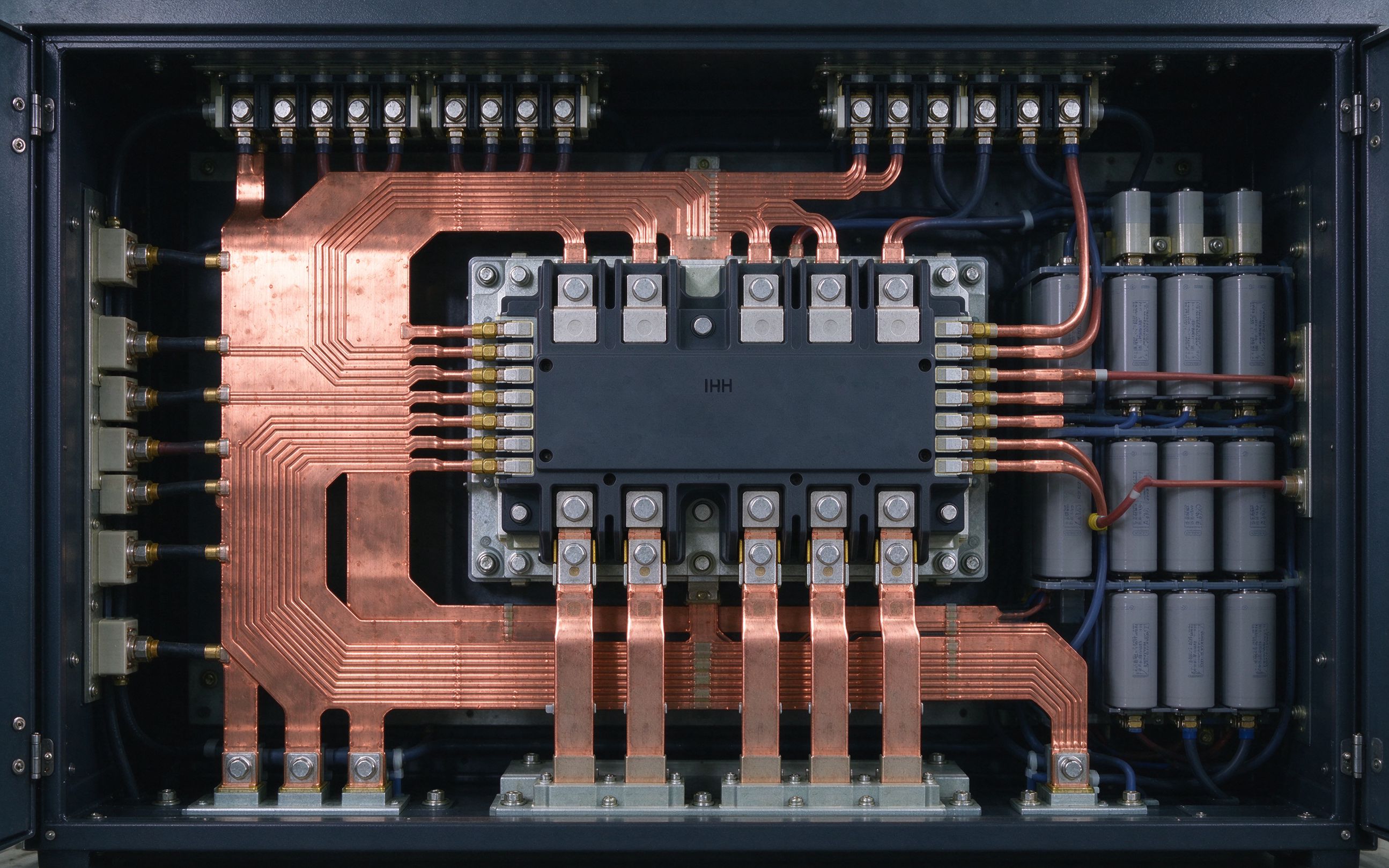
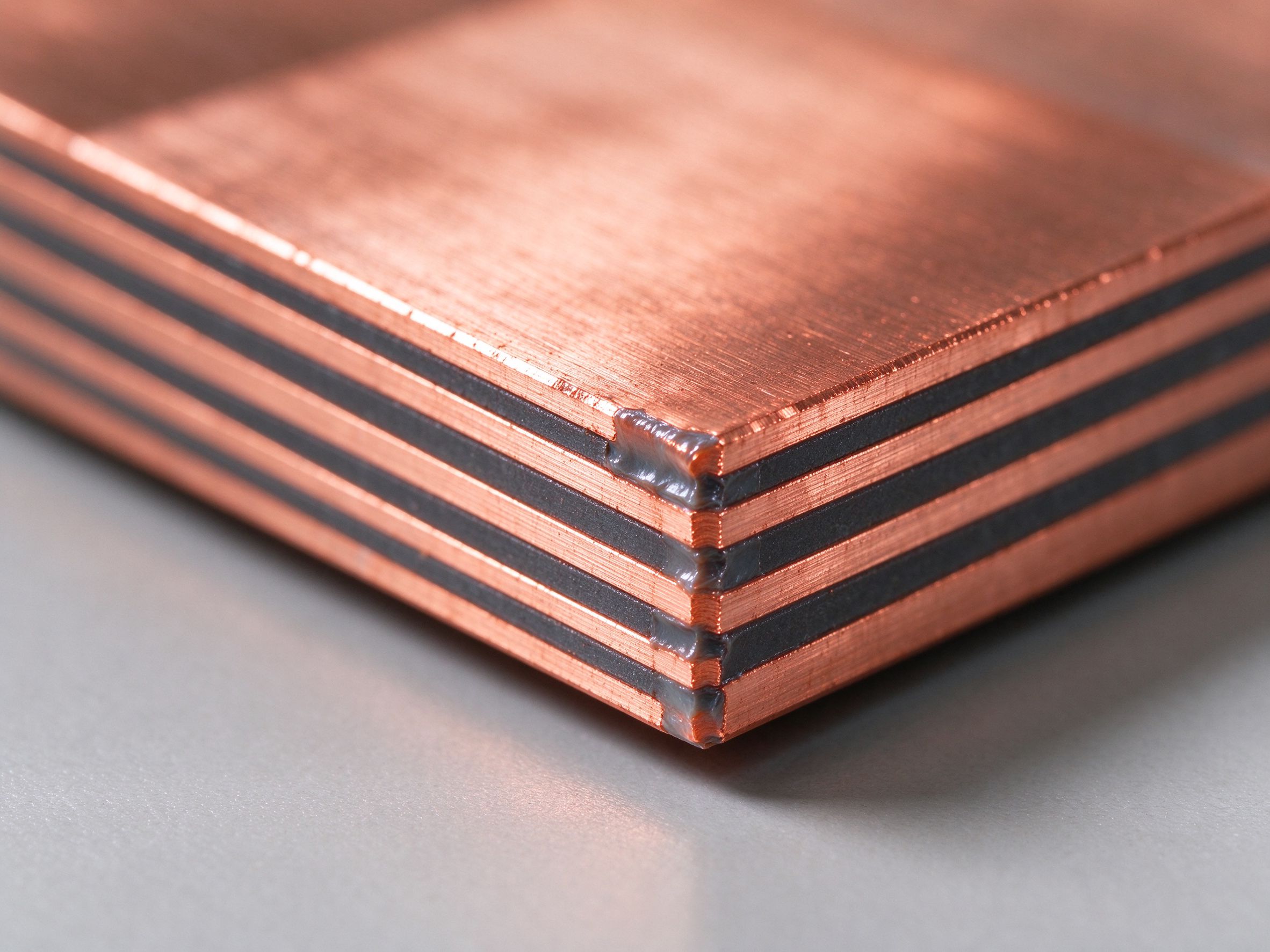
For a laminated busbar, the active cross-section is the sum of the copper area in the layers that actually carry current — not the overall part thickness, which includes dielectric film. A 2-layer busbar with two 1.5 mm sheets at 40 mm wide has a 120 mm² active section, even though the physical part is closer to 3.2 mm thick. This is the number you plug into any ampacity estimate. We cover why laminations beat single thick plates in busbar vs cable and power-electronics busbars.
SHANYUAN publishes current ratings against a fixed reference condition:
That means a busbar rated at, say, 400 A in our tables will reach roughly 70 °C hotspot under those conditions. It is a conservative, reproducible number — not a maximum-melt number. If your design allows a higher hotspot (for example, because your dielectric is Nomex-rated to 180 °C) you can push current higher, but you must then re-check the film, the solder, the terminal creepage and the fastener relaxation. We usually pair this with the dielectric guidance in our material selection guide.
If the actual ambient is higher than 40 °C, the allowable temperature rise shrinks. A practical way to think about it:
Pair this with the ampacity chart on our resources page, which shows how current capacity falls as ambient climbs. For battery packs specifically, the ambient around the busbar is driven by cell temperature, not by room air — see ESS applications and EV applications for how that changes sizing.
Busbars that sit next to each other — positive and negative in a DC link, or several phase bars in an inverter — heat each other. Air cannot circulate between them. Industry experience suggests derating of roughly:
| Arrangement | Typical derating vs free-air single bar |
|---|---|
| Single bar, free air | 1.0 (reference) |
| Two bars <20 mm apart, same load | 0.85–0.90 |
| Three or more bars tightly packed | 0.75–0.85 |
| Bars stacked directly on top of each other | 0.65–0.75 |
These are rule-of-thumb engineering numbers, not substitute for a thermal simulation on a tight design. The key design lever is spacing: even 10–15 mm of air gap between bars recovers a surprising amount of cooling. This is one of the first things we check in a DFM review.
A busbar inside a sealed or IP-rated cabinet with no forced air sees a much higher effective ambient. Derate by a further 10–20% for a sealed enclosure, and more if the cabinet also contains semiconductors, magnetics or resistors dumping heat into the same air. Forced air or a fan allows closer to free-air ratings.
Air gets thinner above ~1000 m, so convective cooling weakens. A common industry convention is roughly a 1% ampacity reduction per 100 m above 1000 m. For a busbar going to a 2500 m solar site, plan for about 10–15% less current than the sea-level number.
At DC, current distributes evenly across the copper cross-section. At 50/60 Hz AC, skin effect already thins the effective conduction layer, and at higher switching ripple frequencies (a few kHz and up) it matters even more. Practical consequences:
Even if the copper can carry the current, three other things set the real upper bound:
At SHANYUAN we routinely build laminated busbars up to around 1000 A continuous on multi-layer C11000 copper, but the exact number always comes back to the reference ambient, the derating factors and the dielectric. For very high-current single-layer designs, two parallel layers are almost always better than one thick plate.
That is the flow we run on every custom busbar quote. If you would rather skip the spreadsheet, send the drawing, current profile and enclosure conditions to busbar@shanyo.com or use /contact/. We will size the part, quote it, and ship samples in 5–7 working days. As a busbar manufacturer and busbar supplier focused on custom laminations, SHANYUAN does not push a one-size catalog — every copper busbar current rating we quote is tied to your actual install conditions. See also the design guide, busbar vs cable and the ampacity chart.
Engineers sometimes ask why a laminated busbar of the same copper cross-section as a heavy cable bundle does not simply carry the same current. The answer is surface area and heat sinking. A bundle of round cables has rough, intersticed surfaces that trap warm air between wires; a flat laminated busbar has broad, planar faces that radiate and convect freely, and it can be bolted directly to a chassis that acts as a heat sink. That is why the same 120 mm² of copper often runs cooler in a laminated busbar than in a cable bundle of the same area. We unpack the mechanical and electrical trade-offs in busbar vs cable, and the thermal side of the comparison is why laminated busbars are the default in inverter and EV DC links.
Continuous rating is one question; pulse and short-duration overload is another. A busbar can carry several times its continuous current for a few seconds because the copper has significant heat capacity. Roughly, the temperature rise under a short pulse scales with I²·t divided by the copper mass and specific heat. For an inverter start-up, a battery inrush or a motor start, the copper heats up, absorbs the pulse, and then cools back down between cycles. The limits are set by the dielectric maximum temperature and by fastener relaxation, not by copper melting. If your application has a known pulse profile, send it with the drawing; we will size the copper so the pulse does not push the hotspot past the film rating. This is a standard input on every custom busbar quote we issue.
A last practical tip: when you size a busbar from our ampacity chart, leave roughly 15–20% headroom above the calculated steady-state current. That headroom covers mild derating surprises (a fan that fails, a filter that clogs, a summer ambient that runs hotter than the spec sheet assumed) and it keeps the hotspot comfortably below the dielectric limit for the life of the equipment. Under-sizing is the most common field-failure mode we see on returned parts; over-sizing by one sheet thickness is almost always cheaper than a warranty claim. Send us your current profile and we will confirm the margin during the custom busbar quote.
PET, Nomex and DLF epoxy are the three dielectrics we laminate into SHANYUAN busbars every
Read article
From C11000 copper coil to a fully sealed, tested multi-layer busbar, this walkthrough exp
Read article
Every hour spent on DFM before a custom busbar quote saves a week of rework. This is the c
Read articleSend the current profile, voltage class and terminal types — our engineers reply within one business day.
Send drawings, current ratings and voltage class — DFM feedback and a quotation within one business day.
