Most busbar specifications start with the electrical question — what current, what voltage — and stop there. The failures that actually cost money start later, and they cluster into six repeatable modes: over-temperature, loose joints, corrosion, thermal-cycling fatigue, vibration, and insulation breakdown. Purchasing managers and engineers who pick busbars on ampacity alone are betting on the easy criterion and ignoring the hard ones. This guide reverses the order: duty first, failure modes second, selection third.
Most busbar specifications start with the electrical question — what current, what voltage — and stop there. The failures that actually cost money start later, and they cluster into six repeatable modes: over-temperature, loose joints, corrosion, thermal-cycling fatigue, vibration, and insulation breakdown. Purchasing managers and engineers who pick busbars on ampacity alone are betting on the easy criterion and ignoring the hard ones. This guide reverses the order: duty first, failure modes second, selection third.
An ampacity number tells you the current a busbar can carry; it tells you nothing about whether that busbar will still be carrying it in year three. The selection criteria that matter are the failure modes — each one maps to a design decision, and each design decision maps to a line item in the quotation. Buyers who understand the map can read a quote like a specification; buyers who do not are comparing vendors on price and hoping.
The discipline is simple: state the duty envelope first (current, voltage, ambient, cycles, environment), then walk the failure-mode list against it. Every application has one or two dominant modes; the selection should be built to defeat those, with the rest as hygiene.
The six modes cover the field: over-temperature — the design carries more current than the geometry, joint or cooling path can shed; loose joints — contact resistance grows as bolts relax, creep and plating degrade; corrosion — the contact interface oxidizes and resistance climbs; thermal-cycling fatigue — daily temperature swings work the interface until it gives; vibration — mechanical fatigue at supports, terminals and welds; and insulation breakdown — PD, tracking or creepage failure ends the life regardless of the metal.
Rarely does a field failure arrive in one pure form — a corrosion failure usually shows up as a hot joint, and a vibration failure often appears first in a thermal image. But each mode has a distinct prevention logic, and selection is about applying the right logic to the right duty.
Over-temperature is the most common busbar failure because it is the easiest to create and the hardest to see early. The design sins are classic: cross-section sized for average current rather than worst-case, terminals with insufficient contact area, support spacing that blocks natural convection, or plating that adds resistance at the joint. A 30°C-rise design at rated current becomes a 50°C-rise design when the ambient is hot and the air cannot move.
The selection response is a real thermal calculation, not a table lookup. Our ampacity chart gives the starting numbers and the thermal management design guide walks the full heat balance. Buyers should ask for the temperature-rise calculation at the worst-case ambient — a supplier who cannot produce it is quoting on hope.
A bolted busbar joint is a managed compromise: the interface carries current through microscopic contact points, and everything — torque, plating, flatness, washer stack, creep — decides how many of those points survive. Field data is blunt about the economics: connections that get full joint preparation — disassembly, cleaning, fresh antioxidant compound, correct torque — improve in about 92% of cases, versus roughly 20% for simple retorquing alone.
The selection consequence is that joint design is a first-class specification item, not an assembly detail. Ask the supplier for the joint design rules: connection design guidance, torque documentation, washer and plating specification, and a retorque schedule matched to the duty. The vibration and bolted joint guide covers the mechanical half of the same problem.
Corrosion attacks the contact interface first and the busbar looks fine while it is failing. Tin plating oxidizes, silver tarnishes, nickel passivates — each with different consequences for contact resistance. In humid, coastal or electrolyte environments, the corrosion envelope decides the plating system: thickness, base layer, edge coverage and whether the design needs sealed edges at all.
The selection rule is environment-driven, not price-driven. The plating and corrosion guide compares tin, silver and nickel systems by duty; the rule of thumb that survives every debate is that thickness and edge coverage are the variables that actually protect the interface, and both show up in the specification and the price.
Every power cycle heats the busbar and every off-cycle cools it; the joint interfaces and insulation see the resulting strain. At 7,000 daily cycles — a 20-year asset — even small interface weaknesses accumulate into failures. The fatigue-sensitive points are the ones that mix materials: bolted interfaces with plating, welded joints with heat-affected zones, and insulation edges that flex against copper.
Selection against cycling fatigue means choosing interfaces with documented cycle life at the real temperature swing, not the lab swing. The thermal cycling reliability guide explains the interface mechanics and the qualification evidence to demand — cycle counts, failure criteria and the monitoring indicators that prove a design.
Rail, marine, wind and vehicle applications vibrate continuously, and the busbar responds as a mechanical structure: supports loosen, terminals fret, welds fatigue, and the first sign is often a crack found at inspection, not a trip. The failure physics is amplitude and frequency against the natural modes of the busbar geometry, which is why support spacing and terminal design matter as much as the electrical sizing.
The selection response is a vibration-qualified design: tested at the application's spectrum, not a generic shake test. Our vibration and bolted joint guide covers spring washers, locking hardware and support rules; buyers in moving applications should put the vibration test report on the RFQ requirements list.
Short-circuit current is a different regime: thousands of amperes for milliseconds, with electromagnetic forces that can permanently bend an unsupported busbar. The mechanical design must carry the peak force — the bolt-down spacing, the bracing, the conductor section all respond to the prospective fault current, not the running current.
Selection against this mode is a calculation, not a guess. The short-circuit withstand guide walks through force estimation and bracing rules; the RFQ should state the prospective fault current and ask for the withstand calculation, because the difference between a braced and an unbraced design is visible in the quote and invisible in the photo.
Above a few hundred volts, the insulation system becomes the life-limiting component. Partial discharge, tracking and creepage failure end the busbar regardless of how good the copper is. The failure drivers are voltage, environment and material quality: voids in the laminate, edge geometry, humidity, contamination and altitude all move the PD inception voltage.
The selection rule for any busbar above about 1,000V is PD-tested insulation at the worst-case condition — humidity and altitude declared, not lab conditions. The PD-free design guide covers the material and geometry choices; the procurement rule is that the test condition must be in the spec, or the certificate means nothing.
The mapping is the whole method: each failure mode maps to a selection rule, and each rule maps to a specification line and a question for the supplier. Over-temperature maps to a real thermal calculation at worst-case ambient; loose joints to joint design documentation and a retorque schedule; corrosion to environment-matched plating with documented thickness; cycling fatigue to cycle-tested interfaces; vibration to tested support and terminal design; short-circuit to a withstand calculation; insulation to PD testing at declared conditions.
When you write the RFQ this way, the suppliers that survive are the ones with the engineering depth — and the ones that do not are filtered out before the price comparison, which is where they would otherwise win.
The practical matrix starts with the duty profile and reads out the design response. High current, benign environment, few cycles — distribution busbar — starts with ampacity and joint design. High current, daily deep cycles — storage DC-link — adds cycling fatigue and plating to the critical list. Outdoor, humid, high voltage — solar and wind interconnection — makes insulation and corrosion the dominant drivers. Moving equipment — rail, marine, EV — puts vibration and mechanical qualification first. Aggressive chemistry — flow battery, electrolyzer — elevates plating and sealed edges.
No single busbar optimizes all six; the art is deciding which two or three modes dominate your duty and selecting against them. Every other criterion is secondary and should be traded only when the price difference is real.
Terminal geometry is a failure-mode decision wearing a cost hat. Bolted studs give serviceability and predictable torque; blade terminals give fast assembly and clip retention; weld tabs give the lowest resistance but no field serviceability; crimp and compression joints suit specific connector systems. The duty decides: high-vibration applications lean toward locking hardware and weld-free designs; high-cycle applications want bolted interfaces with documented retorque; sealed outdoor enclosures may prefer weld tabs that never loosen.
Our terminal machining guide covers the fabrication side — hole position, flatness, thread quality. The selection side is simpler: ask which failure modes the terminal choice defends against, and whether the joint is serviceable for the asset life you are planning.
Plating is the environment's answer to corrosion and contact resistance, and the selection matrix is well established. Tin: the workhorse for indoor power at moderate temperature, cheap and solderable, soft enough to creep into surface roughness. Silver: lowest resistance and best for high-frequency and high-cycle contacts, at a metal cost premium and tarnishing that matters in humid air. Nickel: a barrier layer under other platings and a hard, wear-resistant surface, at higher contact resistance than tin or silver.
The rule is not which is best — it is which is right for your environment and duty. The plating and corrosion guide and the copper vs aluminum resource together cover the selection inputs, including the bimetallic joint cases where plating is the corrosion barrier.
Insulation selection follows voltage and environment, not preference. PET film: the industrial default — strong, thin, high dielectric strength, and the right answer for most sub-1,000V indoor duty. Nomex paper: higher thermal class and mechanical toughness, the choice when heat or mechanical abuse dominates. DLF and epoxy systems: contoured insulation for complex geometry and edge protection where film cannot wrap cleanly. Above 1,000V, partial-discharge performance joins dielectric strength as the deciding property, and the material must be proven at the operating humidity and altitude.
The design guide and our dielectric selection article compare the systems by property; the procurement rule is to declare the voltage, environment and test condition and let the supplier's engineering pick the laminate — then verify with the PD and dielectric evidence.
The checklist has eight questions, one per failure mode plus two commercial ones. Thermal: what is the temperature-rise calculation at my worst-case ambient? Joint: what are the torque, washer and plating specifications, and what is the retorque schedule? Corrosion: what plating thickness and edge coverage, per which standard? Cycling: what is the tested cycle count at my temperature swing? Vibration: what spectrum was the mechanical qualification run against? Fault: what is the short-circuit withstand calculation? Insulation: at what humidity and altitude was PD tested? Metal: what is the copper weight and the metal index basis of the quote?
A supplier who answers all eight with documents is running failure-mode engineering as standard practice. A supplier who answers three and waves at the others is where the next field failure is waiting. The full framework is in our RFQ supplier evaluation guide and the manufacturer selection guide.
The final principle is that selection should start from failure evidence, not from datasheets. Every industry has its pattern — storage DC-links fail at joints under daily cycling, outdoor solar interconnections fail at insulation edges in humidity, rail and marine equipment fails at supports and terminals under vibration. If you know your industry's pattern, you know which two questions on the checklist are the real test.
At SHANYUAN we publish the failure-mode engineering openly — quality documentation, test evidence and the factory tour — because selection is only as honest as the evidence behind it. Start your next busbar selection with the duty profile and the failure list; the specification will write itself.
Field experience across industries converges on one pattern: the joint is where the failure starts and the thermal image is where it shows first. A connection that carries current through a degraded interface dissipates heat at the contact points, and under load that heat is visible as a hotspot against the adjacent conductor. The maintenance discipline that catches it — load-corrected thermal imaging, micro-ohm trending, joint preparation — is described in our maintenance and troubleshooting guide published today.
The selection connection is direct: the same joint design decisions that prevent hotspots — contact area, plating, torque, washer stack — are the decisions made at selection time. A buyer who chooses a busbar with documented joint engineering is buying a smaller maintenance bill for twenty years.
The pattern that has cost storage operators the most in the field is DC-link joint degradation under daily cycling. Every cycle is a temperature excursion at the interface; over thousands of cycles the plating and the clamp relax, contact resistance climbs, and the thermal image begins to show a joint running ahead of its neighbors. The failure is gradual, measurable and preventable — and it is the reason the thermal cycling reliability guide exists as a specification input, not an afterthought.
For selection, the rule is to buy the cycle evidence, not the promise: tested cycle count at the real temperature swing, the failure criteria, and the monitoring indicators. The same discipline applies to the long-duration plants now scaling globally — the long-duration build-out analysis published today makes the 25-year duty explicit.
The second field pattern is insulation-led: outdoor installations where humidity, contamination and UV attack the laminate edges and terminations. The symptom is PD activity or tracking on the surface, often seasonal — worst after monsoon or fog seasons. The selection response is a PD-tested insulation system specified at the real humidity and altitude, with edge geometry designed to keep the field away from the copper.
The PD-free design guide covers the geometry and material choices; the field lesson is that the environment decides the insulation, not the voltage rating alone. Buyers in coastal, humid or high-altitude regions should put the humidity declaration in the spec and demand the test condition with the report.
The most efficient screen in vendor selection is the failure-history question: what have your busbars failed from in the field, and what did you change? A supplier with a documented failure-mode engineering culture answers with specifics — the mode, the fix, the revised test. A supplier without one answers with marketing. The question costs nothing to ask and separates engineering depth from fabrication capacity instantly.
The screening conversation now includes the supply-chain context. In a year when copper supply is constrained and fast-growing programs like India's storage build-out are pulling the same vendor pool, the failure-history screen matters more: the suppliers with evidence-based engineering are the ones holding their quality through the volume surge.
The RFQ response is where the discipline shows. A supplier that returns a failure-mode analysis with the quote — the duty assumptions, the dominant modes, the design response for each, the test evidence — is running the selection framework as standard practice. A supplier that returns only drawings and a price is deferring the engineering conversation to the warranty year, which is where failures actually get expensive.
The documentation standard covers the electrical interface too: the EMI and layout discipline published today is part of the reliability conversation for power converters, since switching-loop geometry and thermal failure share the same layout decisions. Buyers who demand the file with the quote are buying the engineering, not the copper.
Which failure mode should dominate my selection? The one your duty creates: daily-cycling storage DC-links are joint- and fatigue-led; outdoor high-voltage installations are insulation- and corrosion-led; moving equipment is vibration-led; high-current distribution is thermal-led. Map the duty, weight the modes, and select against the top two or three. What evidence should a supplier provide? Thermal calculations, joint and plating documentation, cycle-tested interfaces, PD reports at declared conditions, and the short-circuit withstand calculation — eight items, each tied to a failure mode. Why does joint preparation matter in selection? Because field data shows fully prepared joints improve in about 92% of cases versus 20% for retorquing alone — the joint design you select determines the maintenance bill the plant pays for its whole life.
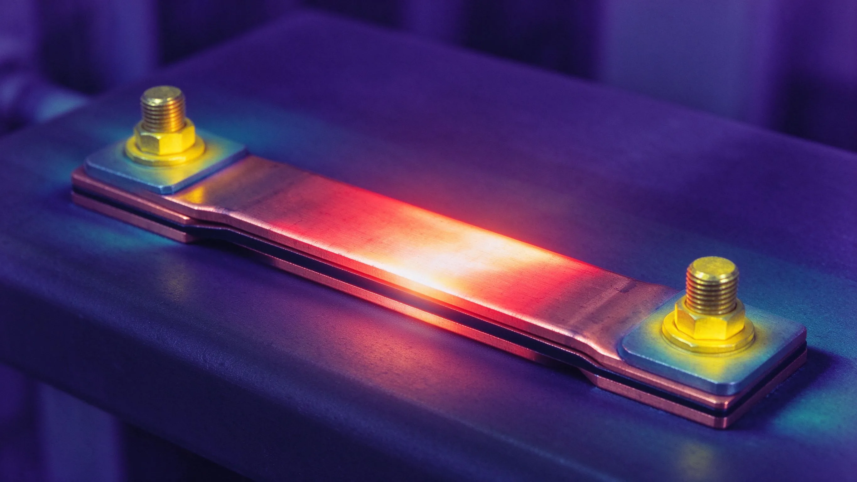
Thermal cycling degrades busbar assemblies from the inside: solder joints crack, bolt pres
Read article
A bolted busbar joint fails in one of two ways: vibration loosens it or thermal cycling fa
Read article
The plating on a busbar contact is a corrosion strategy as much as a conductivity play. Ti
Read article
David Osei is a product marketing engineer covering SHANYUAN's laminated busbar product lines. With 9 years in technical marketing for electrical components, he translates application requirements into product definitions, selection guides and technical content. He holds a B.Eng. in Electrical
Send the current profile, voltage class and terminal types — our engineers reply within one business day.