For a fraction of a second, a short circuit turns a busbar system into a battlefield: peak currents of tens of kiloamps, electromagnetic forces in kilonewtons, and conductors that must hold position until the protection operates. IEC 61439-1 handles the requirement with two declared values — the short-time withstand current Icw (the thermal test, RMS, 1 s or 3 s) and the peak withstand current Ipk (the mechanical test, the instantaneous maximum). This guide walks the electrodynamic calculation behind Ipk — the F = B·I·L physics, the square-law scaling, the support-spacing decision — with numbers from real switchboard designs.
For a fraction of a second, a short circuit turns a busbar system into a battlefield: peak currents of tens of kiloamps, electromagnetic forces in kilonewtons, and conductors that must hold position until the protection operates. IEC 61439-1 handles the requirement with two declared values — the short-time withstand current Icw (the thermal test, RMS, 1 s or 3 s) and the peak withstand current Ipk (the mechanical test, the instantaneous maximum). This guide walks the electrodynamic calculation behind Ipk — the F = B·I·L physics, the square-law scaling, the support-spacing decision — with numbers from real switchboard designs.
Short-circuit withstand is declared as two values because a short circuit stresses the busbar two ways. Icw (rated short-time withstand current) is the RMS current the busbar can carry thermally for a specified time — typically 1 s or 3 s — during which the conductor heats adiabatically and must not exceed its temperature limit. Ipk (rated peak withstand current) is the maximum instantaneous peak the busbar can withstand mechanically — the electrodynamic force that tries to bend the conductors and break the supports (Powerfabric, 2026).
IEC 61439-1 Clause 10.11.8 requires the switchgear manufacturer to declare both; the design must satisfy the thermal check for Icw and the mechanical check for Ipk (Filipino Engineer, 2026).
The peak value depends on the fault asymmetry: i_peak = √2 × Icw × (1 + e^(−π/(X/R))), where the X/R ratio of the fault circuit sets how much the DC offset adds to the AC peak. For a typical 50 kA, X/R ≈ 15 fault: i_peak = √2 × 50,000 × (1 + e^(−π/15)) = 70,711 × 1.811 ≈ 128,057 A (worked example, ECalPro, 2026).
That is the number that matters mechanically: 128 kA peak, not 50 kA RMS. The force calculation below uses the peak, and the difference is the reason designers who use RMS values undersize their supports.
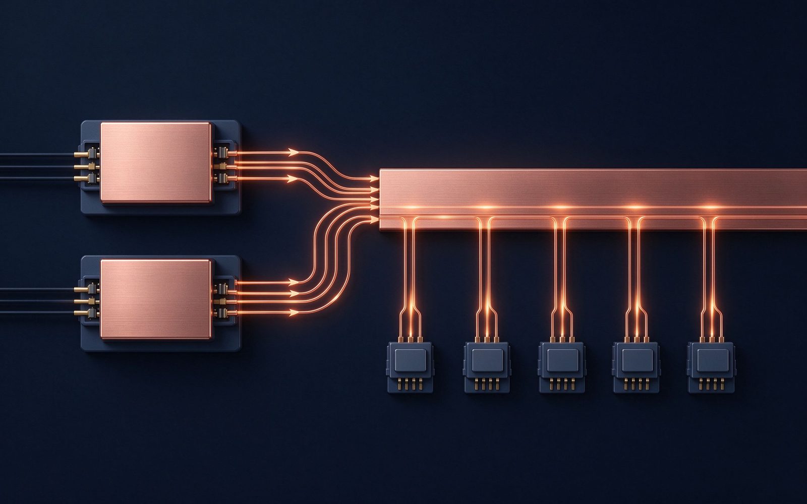
Parallel busbars carrying fault current repel each other with the force F = (µ₀ · I² · L) / (2π · d), where I is the peak current, L the unsupported span, and d the center spacing between conductor paths. At 50 kA over a 1 m span spaced 50 mm apart, that is about 10 kN — enough to crack insulators and loosen joints (GRL Copper, 2026).
The two levers are obvious from the formula: reduce the span L with more supports, or increase the spacing d. Both are design decisions made at the drawing stage, not fixes for a failed type test.
The force scales with the square of the peak current: doubling the peak current creates about four times the force (VIOX, 2026). The consequence is that fault-level increases bite disproportionately: a system upgraded from 50 kA to 63 kA peak (1.26×) sees ~1.6× the force; from 50 kA to 80 kA (1.6×), ~2.5× the force. Support systems sized for the old fault level are structurally inadequate at the new one even when the conductor thermal rating still fits.
This is why the Ipk declaration drives the mechanical design of the whole assembly — supports, brackets, mounting hardware — not just the conductor.
In a three-phase busbar, the forces are more complex than a simple two-conductor repulsion: each phase interacts with the other two, and the worst-case force on the middle phase can exceed the simple pairwise estimate. IEC 60865 (and its predecessor IEC 865) provides the calculation method for rectangular rigid conductors in three-phase systems (Zenodo reference, 2026), with peak-transient factors accounting for the asymmetrical three-phase fault.
The engineering practice is to calculate the force on each phase at the fault instant that maximizes its loading, then size the supports for the worst case — the same rigor that thermal management design applies to the temperature side.
Support spacing converts the force per meter into a force per support, and the span also sets the mechanical natural frequency and the bending stress in the conductor. Practical low-voltage switchboard values: distribution bars at 40–60 kA peak commonly run support spans of 300–600 mm depending on bar geometry; the ECalPro King's Cross example (3,200 A switchboard, 50 kA fault) walks the support calculation step-by-step at peak current 128 kA. The ampacity article covers the thermal side of the same bar; this is the mechanical twin.
The conductor's own stiffness contributes to withstand: a flat bar on edge has a much higher section modulus in the force direction than a flat bar laid flat, and wider bars are stiffer per unit cross-section. The orientation decision — edge-on versus flat — trades enclosure depth against short-circuit stiffness, and the force direction (between adjacent phases) determines which orientation helps.
For laminated busbars, the stack's geometry and the bond between layers matter: a delaminated or poorly bonded stack can fail mechanically before the copper yields, which is why lamination quality is part of the mechanical specification, not just the dielectric one (see the manufacturing process article).
Every support is only as strong as its hardware: the insulator's cantilever strength, the bracket's section, the mounting bolts' shear capacity, and the torque that holds the conductor against sliding. The fabrication tolerances guide covers the hole and bend precision; the short-circuit side adds the requirement that the hardware rating exceed the calculated force with margin — published practice sizes insulators at 2× the calculated cantilever load where standards permit.
Torque matters doubly: undertorqued joints slip under fault force and can weld or gall; overtorqued hardware yields. The terminal connection guide quantifies the torque practice.
The Icw thermal check is an adiabatic heating calculation: during the 1 s or 3 s fault, the conductor heats with negligible heat loss, and the temperature rise is set by I²t / (k·A²), where A is the cross-section. The allowable final temperature for bare copper is around 200–250°C under IEC practice; for insulated conductors, the insulation class sets a lower limit (PET and Nomex limits are covered in our dielectric selection guide).
The cross-section sized for continuous ampacity is usually adequate for Icw — but not always at high fault levels or thin laminates, which is why the adiabatic check is run, not assumed.
Verification follows IEC 61439-1: a short-circuit withstand type test on the representative assembly — the declared Icw for the declared duration, then the peak test — followed by inspection for conductor displacement, support damage and joint integrity. The test's pass criteria include mechanical and dielectric checks afterward, because the assembly must remain serviceable post-fault (Powerfabric, 2026).
For laminated and fabricated busbars, our type-test support includes the fixture design, instrumentation (peak current, force measurement where specified) and the post-test inspection protocol, per the quality system.
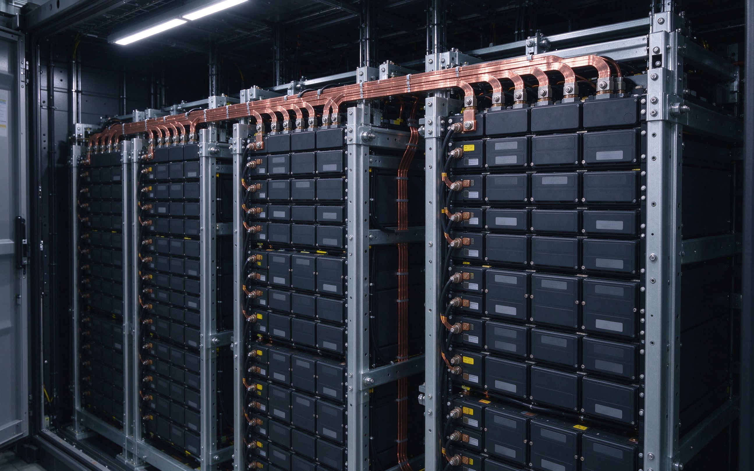
Energy storage systems have a distinctive fault condition: a DC-link fault is fed from both the battery side and the PCS side, so the peak current can be higher than a one-sided utility fault, and the busbar must carry the combined feed until protection operates. The 2026 storage build-out (see our market article) makes this a common design case: rack busbars and PCS DC-links are specified with both-source fault studies, and the support and fuse coordination follow from the study. The GRL BESS fault-current calculation (September 2026) is a practical reference for the ESS case.
Inside a converter, the laminated DC-link's short-circuit case is different in kind: the P/N conductors are close (millimeters, not centimeters), so the repulsive force per amp is high — but the spans are short and the structure is rigid. The laminate's mechanical design — layer bond, terminal anchoring, and mounting — must survive the fault force without delamination or terminal movement, which is why high-current laminates are built and tested as mechanical assemblies, not just electrical ones.
The power electronics busbar qualification includes short-circuit survivability testing for the converter class, matching the SiC power stage trends covered today.
The design input — the prospective fault level — comes from the utility's declared short-circuit capacity at the service point or the system study for the plant. Getting this number wrong in either direction is costly: undersize it and the assembly fails a type test or a field fault; oversize it and the support system and enclosure cost inflate for no benefit. The 2026 practice in switchboard design is a formal fault-level declaration per project (the Filipino Engineer 2026 guide walks a 36 kA/91.6 kA example for an LV switchboard).
The failure modes of an undersized support system: insulator fracture and conductor displacement at the first field fault (arc flash to enclosure, total loss of the board); loose joints and welded contacts from slip during fault; busbar deformation that fails the post-fault dielectric check; and in the worst case, personnel exposure to an arc. The design cost of the correct support system is measured in brackets and spans; the field cost of the wrong one is measured in outages, replacements and safety events.
The discipline is the same one this DFM checklist article applies to manufacturability: the mechanical design belongs on the drawing before tooling, not in the failure report after commissioning.
Short-circuit withstand is two engineering problems with two declared values: Icw for the thermal check (adiabatic heating, RMS, seconds), Ipk for the mechanical check (electrodynamic force, peak, milliseconds). The physics — F ∝ I², the X/R peak factor, the three-phase worst case — turns a 50 kA RMS fault into a 128 kA peak event and a force that scales with its square. The design answers are support spacing, conductor geometry and hardware rating, all decided at the drawing stage.
When you specify the next switchboard, distribution bar or converter DC-link, declare the fault level, run the Ipk calculation, and size the supports from the peak. Our engineers do exactly that on every inquiry, and the type-test evidence ships with the part.
Global energy storage additions are forecast at 158 GW in 2026, up 45% year-on-year, with
Read article
The plating on a busbar contact is a corrosion strategy as much as a conductivity play. Ti
Read article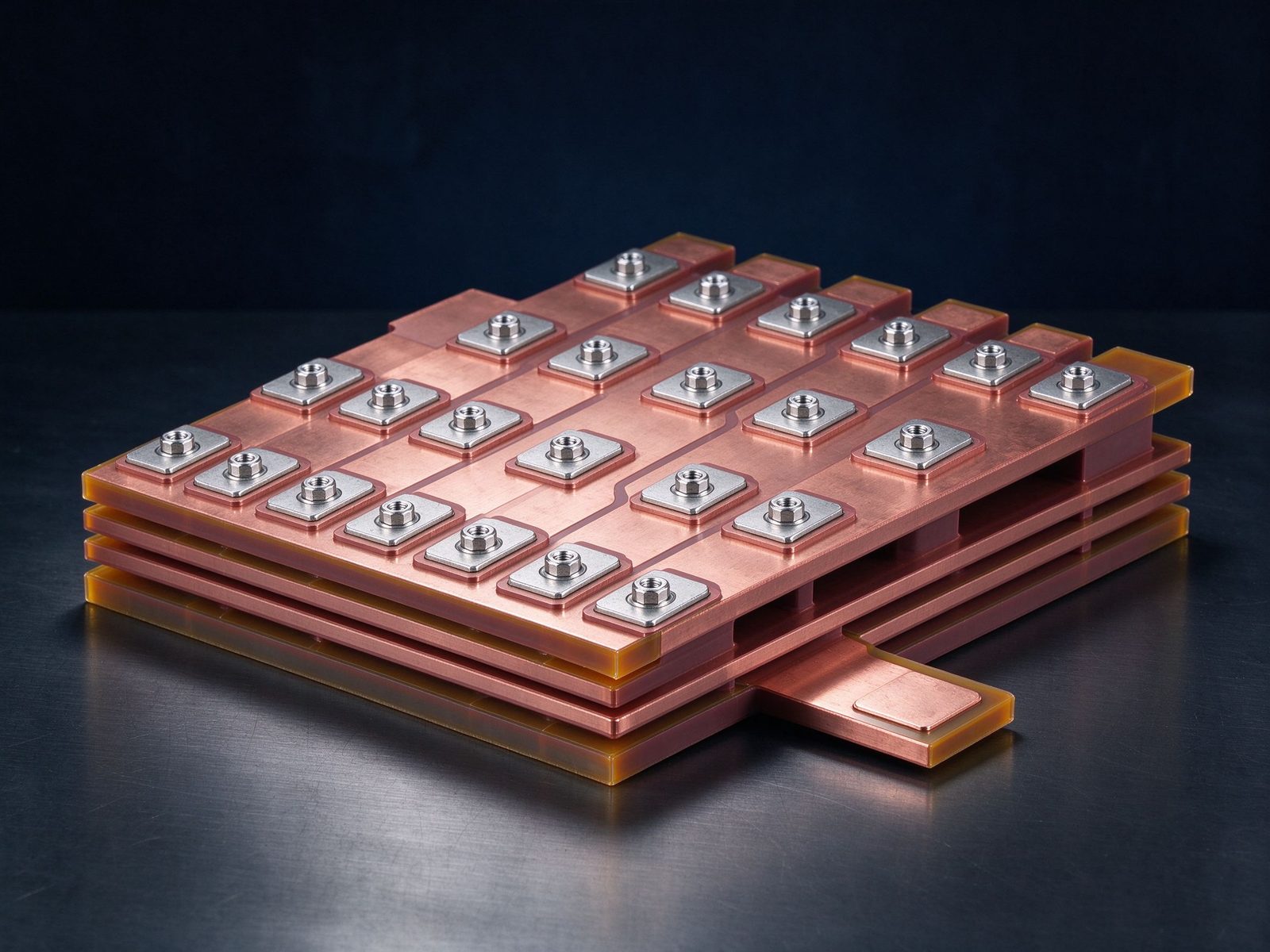
SiC is scaling up — literally. Eight-inch wafer capacity is expanding at double-digit CAGR
Read articleSend the current profile, voltage class and terminal types — our engineers reply within one business day.
