No single number answers 'how many amps can this busbar carry?' The current capacity of a copper rail is the solution to a heat balance: conductor losses (I²R) heat the bar, and surface convection plus radiation remove the heat. The permitted temperature rise — set by the insulation class, the connection hardware and the governing standard — draws the line. This guide walks through the calculation method we use for every SHANYUAN part, with the derating factors that separate a nameplate from a field-reliable rating.
No single number answers 'how many amps can this busbar carry?' The current capacity of a copper rail is the solution to a heat balance: conductor losses (I²R) heat the bar, and surface convection plus radiation remove the heat. The permitted temperature rise — set by the insulation class, the connection hardware and the governing standard — draws the line. This guide walks through the calculation method we use for every SHANYUAN part, with the derating factors that separate a nameplate from a field-reliable rating.
Conductor cross-section sets the raw potential — more copper, less resistance — but the usable current is decided by heat. Every amp flowing through the bar produces I²R losses; the bar heats until the losses balance the heat rejected to the surroundings. The equilibrium temperature is the rating boundary, because above it the insulation degrades, bolted joints oxidize and soften, and the assembly fails in service.
This is why a busbar's continuous rating is always stated together with its temperature-rise limit and ambient: change the enclosure or the ambient and the rating changes. The same bar that carries 652 A at 35°C ambient and 85°C busbar temperature derates to about 508 A at 55°C ambient — a ~22% penalty from ambient alone.
Two standards dominate switchgear and busbar temperature-rise acceptance: IEC 61439-1 (low-voltage switchgear assemblies) and UL 891 (dead-front switchboards). Both verify temperature rise on the assembled product, not on the bare conductor. The commonly applied limits: IEC 61439-1 allows 105 K for bare copper internal connections, 90 K for bare aluminum, and 70 K for terminals for external conductors; UL 891 caps main busbars in a switchboard at 65 K. The contract edition of the standard always takes precedence.
For insulated busbars the limit drops to the insulation material's maximum continuous operating temperature, and the check targets the hot spot at the conductor–insulation interface, with the insulation thickness entering the thermal resistance. This is exactly the case for laminated busbars, where PET or Nomex layers are part of the heat path — our thermal management reference details that treatment.
The classic sizing formula is ΔT = (I/K)² × (1/A), where ΔT is the permitted temperature rise in Kelvin, I the current in amps, A the conductor cross-section in mm², and K a material-and-ventilation constant. Rearranged, the minimum cross-section for a target rise is A = I² / (K² × ΔT).
Published working values: for copper in a ventilated enclosure, K ≈ 8.5 (mid-range). A 2,000 A main busbar designed for 40 K rise needs A = 2,000² / (8.5² × 40) ≈ 1,384 mm², which a 160 × 10 mm bar (1,600 mm²) covers with margin. For aluminum the same math uses the metal's higher resistivity and a K closer to 5–6, producing a larger section — the reason aluminum substitution costs envelope.
Before the full thermal model, engineers use current density as a first pass. For copper busbars in enclosed assemblies, common practice is 1.0–2.0 A/mm² under natural convection, with 1.2–2.0 A/mm² typical for laminated assemblies in a rack; for aluminum, roughly 0.6–0.8 A/mm² at the same temperature class. A 2,000 A copper busbar at 2.0 A/mm² needs 1,000 mm² — achievable with two 80 × 10 mm bars per phase, leaving margin for heating.
The density method is a screening tool, not a final answer: it ignores enclosure, ambient, proximity and altitude. Our ampacity chart tabulates the resulting values for standard sections so a first estimate takes seconds; the verification is the temperature-rise calculation below.
The full method used for a main busbar design: (1) fix the design current and load profile — IEC 61439 practice applies a 125% factor to continuous load current for long-term duty; (2) select the material and read its resistivity at the target temperature — copper rises from ~1.72 µΩ·cm at 20°C (100% IACS) by roughly 0.4%/°C, so at a 105°C operating temperature the resistance is ~40% higher than at 20°C; (3) estimate the cross-section from the current-density rule; (4) compute the surface heat rejection — natural convection plus radiation from the bar's exposed surface area, reduced by the enclosure factor; (5) iterate the cross-section until the equilibrium temperature meets the rise limit with margin; and (6) verify by test on the assembled product, which is what the standards ultimately require.
Step 4 is where engineering judgment lives: a ventilated enclosure can be worth 30–40% more capacity than a sealed one, which is why enclosure type belongs in the specification, not the footnote.
Ambient temperature is the first derating lever. The permitted rise is a fixed budget above ambient: at 35°C ambient a 105 K rise allows a 140°C conductor; at 55°C ambient the same conductor reaches its limit at a much lower current. Typical published derating is 1–2% of current per degree Celsius above the reference ambient, and the worked example earlier — 652 A at 35°C falling to 508 A at 55°C — shows the magnitude.
The practical rule: state every busbar rating with its ambient, and re-run the calculation when the installation ambient differs from the catalog condition. A '600 A busbar' is meaningless without the ambient it was rated at.
The enclosure multiplies the thermal resistance: heat must cross the internal air, the enclosure wall, and then reject to the room. Sealed enclosures trap heat; ventilated ones (IP2X or forced-air) refresh the internal air. Published switchboard tables show a forced-air IP2X arrangement rating a 40/10×2 mm bar pair at 2,640 A versus 2,150 A standard IP2X — roughly 23% more — and the gap widens as ambient rises.
For laminated busbars inside converters and battery modules, the relevant question is how the module airflow passes the laminate. Rack and module designs with plenum airflow over the busbar run at the higher end of the density range; sealed modules must be calculated at the lower end, or with active thermal management.
Busbars rarely run alone. Parallel bars share the air gap, radiate into each other, and each bar's loss heats the neighboring bar — a mutual heating that reduces the per-bar rating. The same is true of a bar mounted near a hot transformer or converter. Standard practice applies proximity derating factors per the arrangement: two parallel bars in the same phase plane lose more than two spaced bars on different levels.
In a laminated busbar, parallel conductor layers are separated by thin dielectrics (PET, Nomex), so the mutual heating is built into the stack by construction — which is why layer count and dielectric thickness are part of the thermal calculation, not just the electrical one. The dielectric selection guide covers the material side of that trade.
Altitude reduces air density, which reduces convective cooling. Common engineering practice derates busbar capacity for installations above 1,000 m, with published factors in the 0.5–1% per 100 m band above the reference altitude, and standards-specific values in IEC and UL documents for switchgear. A 3,000 m solar plant busbar can lose 10–15% of its sea-level rating from convection alone.
Altitude derating compounds with ambient derating, and both compound with enclosure effects. The combined stack can remove 20–40% from the ideal figure, which is why the calculation matters before tooling rather than after a failed type test.
Bulk conductor resistance is set by the copper, but the joints are where resistance grows. Tin plating (our standard surface) controls oxide formation and gives stable, low contact resistance at bolted joints; silver or nickel plating serves higher-duty or higher-temperature contacts. The contact resistance at a properly torqued tin-plated joint is a small fraction of the bar resistance, but a poorly torqued or oxide-contaminated joint can add tens of milliohms and create a hot spot that fails the temperature-rise test even when the bar itself is fine.
The terminal connection guide quantifies contact resistance by method and torque; for the ampacity calculation, the design rule is to budget the joint resistance explicitly and verify by test, especially at terminal interfaces where the 70 K (IEC) or 65 K (UL) limits apply.
A laminated busbar differs from a bare rail in one crucial way: the insulating layers between conductors are also thermal insulators, and they sit in the heat path from the conductor to the surface. PET, Nomex and epoxy DLF all have thermal conductivities far below copper's ~400 W/m·K — typically 0.1–0.3 W/m·K — so a thick stack runs hotter internally for the same surface temperature.
For multi-layer laminates (3, 4, 6 layers) carrying high current, the internal layers have no direct surface contact and cool only through the dielectric and the outer layers — a real penalty that the layer-count and dielectric-thickness parameters capture. This is why SHANYUAN's high-current laminates pair conductor sizing with a thermal check of the stack, and why the power electronics busbar line documents the temperature-rise basis per part.
For many SHANYUAN laminated busbar applications — EV battery interconnects, inverter DC-links, energy storage assemblies — customers specify a conservative temperature-rise budget around 30 K above ambient rather than the 105 K the standards permit for bare copper. The reasons are pack-level: adjacent cells, connectors and electronics are temperature-sensitive, and a cooler busbar extends the whole system's life. At a 30 K budget, the same 1.2–2.0 A/mm² starting density drops toward 0.8–1.2 A/mm², and the copper cross-section grows accordingly.
When you specify a rise limit, the calculation in this guide runs exactly the same — the limit changes, the method does not. The result is a busbar that runs cooler, lasts longer and keeps the neighbors within their thermal budget.
Design a laminated DC-link for 1,250 A continuous with a 30 K rise target in a ventilated rack module at 35°C ambient. Starting density 1.0 A/mm² gives A ≈ 1,250 mm² — a pair of 2 mm layers, each ~625 mm² (say 250 × 2.5 mm per layer). Resistivity check: at ~65°C conductor temperature (35 + 30), copper resistance is ~18% above the 20°C value, so the I²R loss is computed at 65°C, not 20°C. Surface check: the laminate's exposed edges and faces reject heat at natural convection rates typical for a module interior; with the layer-stack internal temperature penalty, the outer-layer temperature lands near 65–70°C, within budget with margin. The 800 VDC data center context is exactly this case: 1,250 A at 800 VDC with a 30 K-class thermal budget.
Every calculation is a prediction; the standards accept only the test. Temperature-rise verification is run on the assembled product with thermocouples at the conductor, joints, terminals and insulation interface, under rated current until equilibrium. IEC 61439-1 and UL 891 define the test conditions, the measurement points and the limits. A failed test sends the design back to the calculation — usually to the derating stack or the joint, not the bulk conductor.
For production, we combine first-article temperature-rise tests with periodic verification and resistance checks on every lot, so the shipped part matches the tested one. The quality system and the insulation testing guide document the test matrix.
The ampacity of a busbar is not a lookup — it is a calculation with six inputs: cross-section, material resistivity at operating temperature, current, permitted rise, ambient, and the derating stack of enclosure, proximity and altitude. Change any one and the rating moves. The reliable path is the one in this guide: start from the current-density rule, run the temperature-rise method, apply the deratings honestly, and verify by test.
When you send SHANYUAN a custom busbar request with the current profile, ambient and envelope, our engineers return the ampacity calculation with the part — the same method in this article, applied to your numbers, before any tooling is cut.
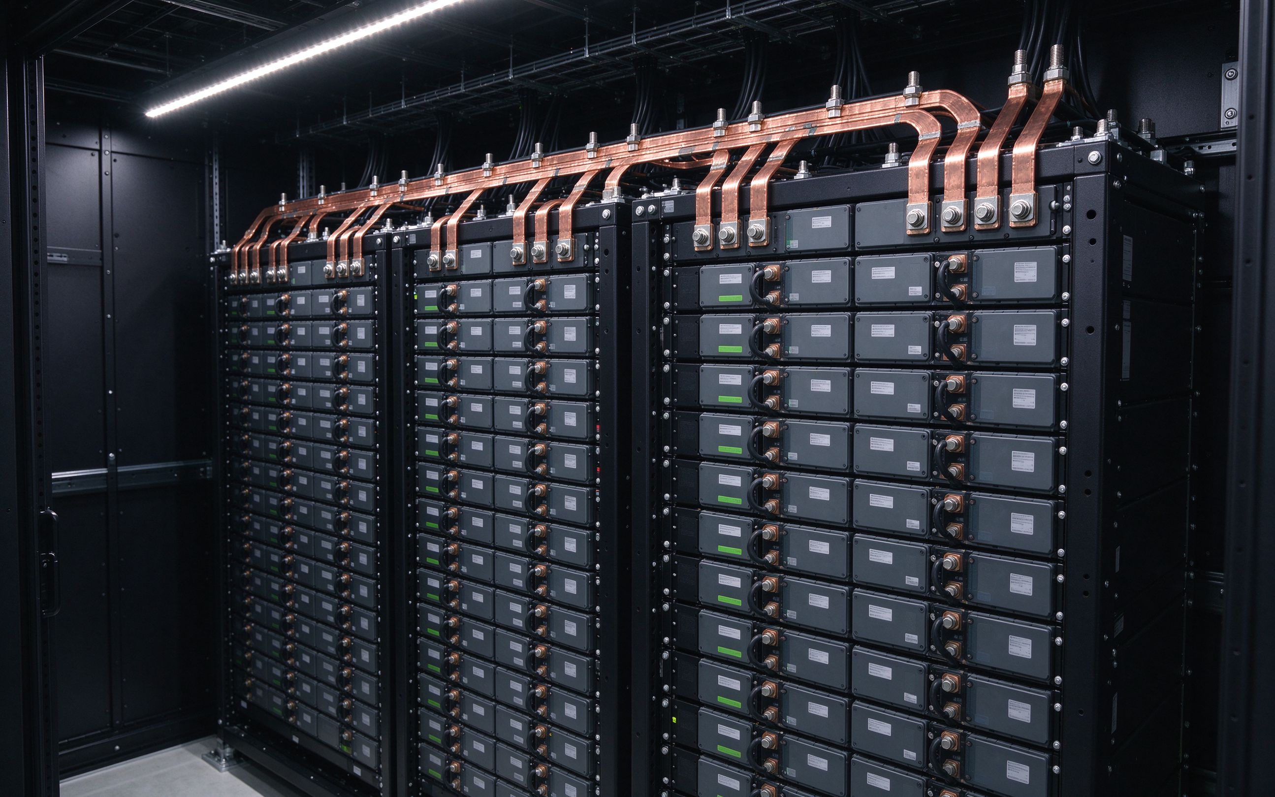
AI racks move from 140 kW to 1 MW by 2027, and the industry answers with 800 VDC distribut
Read article
Record copper prices, a 4.41 copper-to-aluminum price ratio and a structural supply gap fo
Read article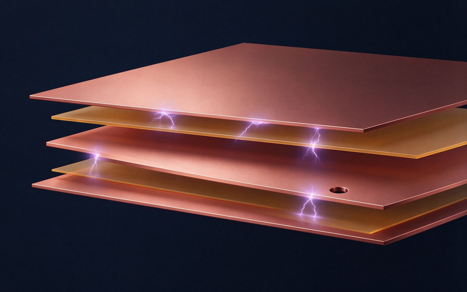
A busbar fails across a surface long before it fails through its insulation if the creepag
Read articleSend the current profile, voltage class and terminal types — our engineers reply within one business day.
Send drawings, current ratings and voltage class — DFM feedback and a quotation within one business day.
