The two distances that keep a high-voltage busbar alive are clearance — the shortest path through air between conductors — and creepage — the shortest path along an insulating surface. For laminated busbars carrying 400 V to 1,500 V DC, IEC 60664-1 is the governing dimensioning standard, and the numbers it produces are smaller than intuition suggests until the working voltage, pollution degree and material group are all accounted for. This guide walks through the method as we apply it to real laminate stacks, terminals and mounting hardware.
The two distances that keep a high-voltage busbar alive are clearance — the shortest path through air between conductors — and creepage — the shortest path along an insulating surface. For laminated busbars carrying 400 V to 1,500 V DC, IEC 60664-1 is the governing dimensioning standard, and the numbers it produces are smaller than intuition suggests until the working voltage, pollution degree and material group are all accounted for. This guide walks through the method as we apply it to real laminate stacks, terminals and mounting hardware.
Clearance is the shortest distance in air between two conductive parts. It is dimensioned to withstand transient overvoltages — the impulse events from switching, faults or lightning coupling — and it depends on peak voltage and altitude. Creepage is the shortest distance along the surface of the insulation between the same conductors. It is dimensioned to prevent tracking: the gradual carbonization of a contaminated surface under sustained voltage and moisture, which forms a conductive path that ultimately shorts the conductors.
Practically, creepage is almost always the larger of the two numbers at typical busbar voltages, and it is the one that catches designers who think only about air gaps. A laminate with a generous clearance gap can still fail across the surface of a PET or Nomex edge if the creepage path along the insulation is too short and the pollution degree is high.
IEC 60664-1:2020+AMD1:2025 — Insulation coordination for equipment within low-voltage supply systems, Part 1 — covers equipment with rated voltage up to AC 1,000 V or DC 1,500 V, frequencies up to 30 kHz, and altitudes up to 2,000 m with guidance for higher. It is the horizontal standard that defines the dimensioning tables and the electrical test methods used by downstream product standards.
The 2025 amendment added 1,500 V DC into the tables and restructured the clearance and creepage clauses with flowchart annexes (G and H). For busbar work above 1,500 V DC — the emerging 800 VDC data center distribution stays inside this standard, but future higher-voltage DC sections approach it — IEC TS 62993 gives guidance up to 2,000 V AC and 3,000 V DC.
DC is harder on insulation than AC of the same RMS value because there are no zero crossings: the stress is continuous, and any surface contamination has no half-cycle to discharge. IEC 60664-1 addresses this with a DC coordination factor of about 1.5×: a DC working voltage is coordinated at 1.5 times its value as an equivalent AC figure.
So an 800 VDC busbar is dimensioned for clearances and creepage equivalent to a 1,200 V system; a 1,000 VDC PV combiner bus is coordinated at 1,500 VAC-equivalent. Published worked examples confirm the scale: a 1,000 VDC breaker in an outdoor enclosure at pollution degree 3, material group IIIa, needs about 12.5 mm creepage and 8 mm clearance. Those are large numbers relative to the package size of most power electronics — which is exactly why the voltage class decision drives busbar geometry.
The pollution degree describes the microenvironment at the insulation surface, not the building. IEC 60664-1 defines four degrees: PD1 is a protected environment with no pollution influence; PD2 allows normally non-conductive pollution with temporary conductivity from condensation; PD3 covers conductive pollution or dry pollution that becomes conductive with condensation; PD4 is severe continuous conductive pollution.
For busbars the practical mapping is: sealed inverter and battery modules are often PD2; PV combiner boxes, ESS racks and outdoor equipment are PD3; coastal and industrial dust environments push toward PD3–PD4. Coating or sealing does not automatically reduce the pollution degree — the reduction depends on the protection method actually meeting the standard's criteria. A conformal-coated or fully potted busbar can qualify for a lower degree only if the coating system is qualified for that claim.
Tracking resistance is quantified by the Comparative Tracking Index (CTI), measured per IEC 60112. IEC 60664-1 groups materials: Group I has CTI ≥ 600; Group II, 400–599; Group IIIa, 175–399; Group IIIb, 100–174. The lower the group, the longer the required creepage at a given voltage and pollution degree.
For laminated busbar dielectrics this is a real selection criterion, not a label: a PET film may test at CTI above 300 (Group IIIa) in one formulation and above 400 (Group II) in another, depending on fillers and surface treatment. Nomex and epoxy DLF coatings behave differently again. The correct practice is to use the documented CTI of the actual material lot — our insulating film and epoxy coating data sheets carry these values — rather than assuming a family name guarantees a group.
The full creepage table (IEC 60664-1 Table F.4/F.5) spans every working-voltage row for each material group and pollution degree. A widely quoted subset shows the scale at common voltages for basic insulation (from Texas Instruments' published extraction):
At 400 V working voltage, PD2: Group I needs 2.0 mm, Group II 2.8 mm, Group III 4.0 mm. At 800 V, PD2: 4.0 / 5.6 / 8.0 mm. At 1,000 V, PD2: 5.0 / 7.1 / 10.0 mm. Under PD1, all material groups collapse to much smaller numbers (1.0 mm at 400 V, 2.4 mm at 800 V, 3.2 mm at 1,000 V) — which is why a genuinely sealed busbar module can run tight, and why an open one cannot.
For reinforced or double insulation the values double. These numbers are the reason a 1,000 VDC busbar terminal layout needs physical spacing that surprises first-time designers.
On a laminated busbar, creepage paths appear in three places: (1) along the cut edge of the insulation between adjacent conductor layers — the edge termination; (2) around terminal studs where the conductive hardware emerges through the dielectric; and (3) across the surface between adjacent terminals, especially at different potentials, such as DC+ and DC− studs on an inverter DC-link.
The design measures are: overlap the dielectric layer beyond the conductor edge so the creepage path runs along the film surface rather than ending at a burr; specify the terminal stud insulation (shoulder washers, insulating sleeves) to extend the surface path; and set terminal pitch so the surface distance between studs meets the table value for the actual voltage and PD. Slotting the insulation between terminals — a groove that lengthens the surface path — is the classic IEC method (the standard's Table 1 defines how grooves count toward creepage).
Air dielectric strength falls with altitude because the air is thinner, so clearance distances must be multiplied by altitude correction factors above 2,000 m. IEC 60664-1's Table F.10 gives the factors: at 3,000 m multiply by 1.14, at 4,000 m by 1.29, at 5,000 m by 1.48, relative to the 2,000 m baseline. Creepage distances are not altitude-corrected the same way — tracking is a surface phenomenon largely independent of air density — which is another reason creepage tends to dominate the design at altitude.
Busbars for EV charging infrastructure, wind turbine converters and high-altitude solar plants (the renewable application space) routinely need the altitude correction applied. The correction multiplies the clearance, and since clearance is rarely the larger number, the envelope impact is usually modest — but it is mandatory to apply.
Below the coordinated voltage, a busbar can still fail by partial discharge (PD) if the insulation system has voids, sharp edges or poor edge termination. PD is a local discharge in a void or at a high-stress point that erodes the insulation over time, and it is a separate failure mechanism from tracking. The design rules overlap with creepage — both reward clean edges and generous paths — but PD control adds its own requirements: void-free lamination, rounded conductor edges, and adequate dielectric thickness for the peak voltage.
IEC 60664-1 references partial discharge testing for insulation coordination, and our partial discharge reference and the insulation testing guide cover the test methods in detail. For 800 VDC class parts, PD inception voltage is part of the acceptance criteria, not an optional extra.
The terminal is where clearance and creepage design most often fail, because a stud penetrating the laminate creates both a through-void risk and a surface path along the stud shoulder. The standard countermeasures: use insulating shoulder washers or machined sleeves that extend the surface path along the stud; countersink or radius the conductor edge around the stud hole to kill the electric field enhancement; and specify the stud material and finish so no galvanic surface contamination forms.
On multi-terminal parts — an inverter DC-link with DC+, DC− and sense terminals — the pitch between studs must satisfy the creepage table at the actual voltage difference between them, not the nominal bus voltage. The power electronics busbar product line and the terminal connection guide detail the hardware side of these decisions.
Epoxy DLF (discrete laminated film) and other coatings are legitimate creepage tools: a conformal or molded coating can be counted toward the pollution degree reduction or the effective creepage only if the protection method meets the standard's criteria, and the coating thickness, adhesion and coverage must be qualified. An unqualified 'paint it and hope' approach is the classic field failure.
Where coating is qualified, it buys back envelope: a coated 1,000 VDC busbar can run tighter than an open one because the surface path is protected from contamination and the effective environment is closer to PD1/PD2. SHANYUAN's DLF epoxy coating and the solid-insulated busbar line are built on this principle, with the coating qualification documented per application.
In practice we dimension a busbar's insulation geometry in this order: (1) establish the coordination voltage — working voltage, DC factor applied, overvoltage category agreed; (2) classify the pollution degree of the actual installation environment; (3) select the dielectric and read its documented CTI to assign the material group; (4) read the creepage table for the working voltage, PD and material group, applying reinforced/double factors if required; (5) compute clearance from the transient overvoltage tables, applying the altitude factor; (6) lay out terminals and edges so both distances are met with margin; and (7) verify by PD and dielectric tests on first articles. Steps 1–6 are drawing-time; step 7 is test-time, and it is not optional for voltage classes above 600 V.
Take the 800 VDC DC-link case. Coordination voltage ≈ 800 × 1.5 = 1,200 V-equivalent. Inside an enclosed rack module with filtered air, PD2 is a reasonable classification. With a PET dielectric at CTI ~300–400 (Group IIIa–II), the creepage table for ~1,200 V, PD2, Group II–IIIa lands in the 5–10 mm band — call it 8 mm for margin. The stud-to-stud pitch on the DC-link laminate is then set by an 8 mm-plus surface path along the insulator, which with shoulder washers translates to a 25–30 mm stud pitch in practice. Clearance at 1,200 V-equivalent transient peak in the same enclosure is smaller, roughly 3–4 mm at 2,000 m. The creepage number drives the layout, exactly as expected.
Four mistakes recur in busbar drawings we review for custom designs: (1) dimensioning clearance only and ignoring creepage — the air gap is fine while the surface path shorts; (2) assuming FR4-grade or generic names guarantee a material group — the actual film's CTI must be read; (3) treating the room as the pollution degree — the microenvironment at the laminate surface is what counts; and (4) forgetting the DC factor on 400–1,500 VDC busbars, which under-dimensions every 800 VDC and 1,000 VDC design by a third. Each of these is caught in DFM review before tooling, which is precisely what the review is for.
Insulation coordination is only as good as its evidence. For every voltage-class busbar we ship, the documentation package includes: the coordination voltage calculation, the PD classification rationale, the dielectric CTI data, the creepage/clearance dimensioning against the standard's tables, and the first-article test report (dielectric withstand, PD inception where specified, and dimensional inspection). This is the same discipline behind our quality system and it is what lets a customer's safety engineer sign off without re-deriving the numbers.
If you are dimensioning a 400 VDC to 1,500 VDC busbar and want the insulation geometry checked before tooling, send the drawing and voltage class — our insulation engineering team returns the coordination calculation with the part.
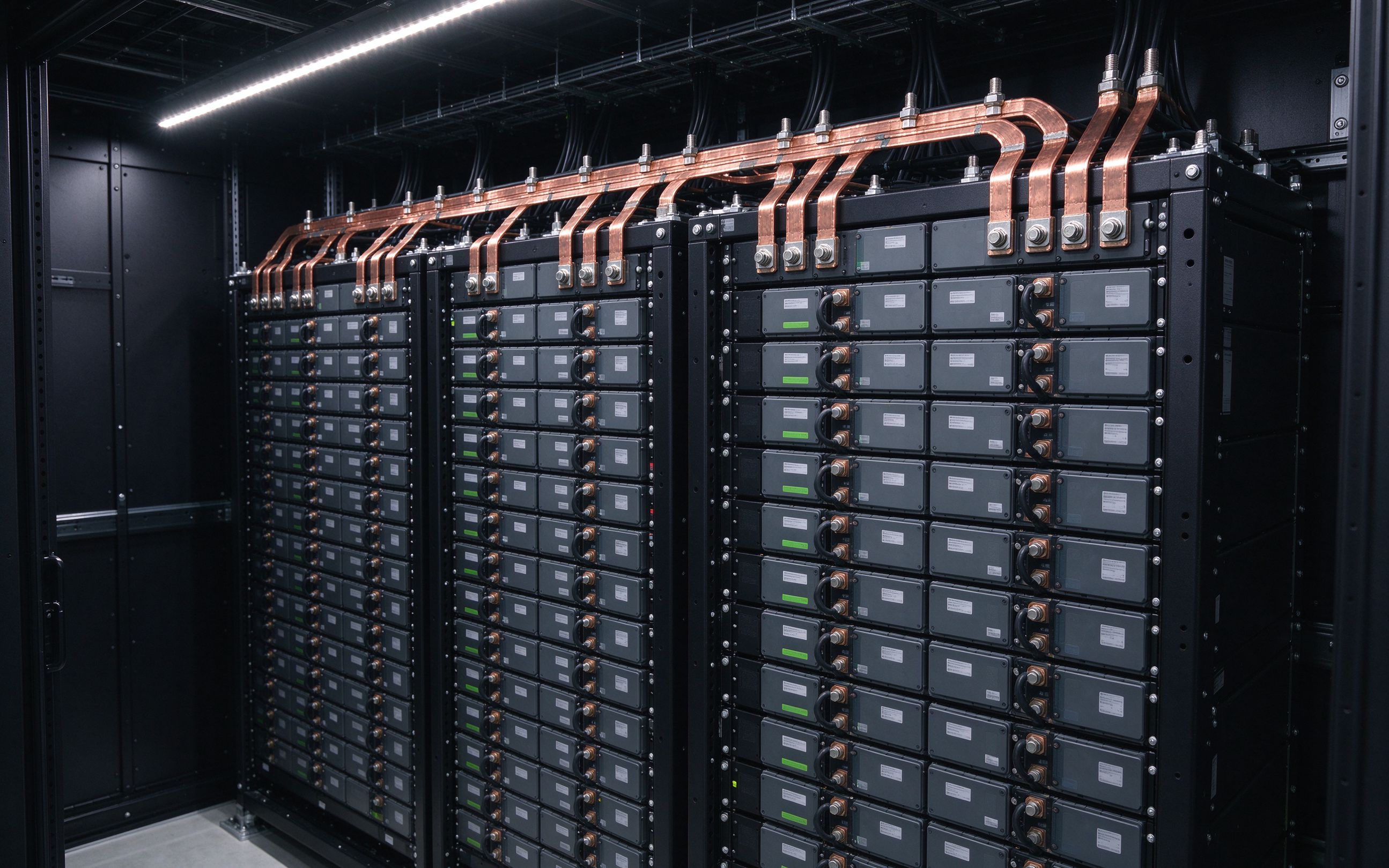
AI racks move from 140 kW to 1 MW by 2027, and the industry answers with 800 VDC distribut
Read article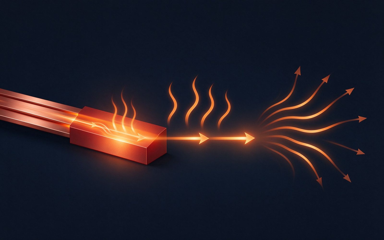
A busbar's rating is not a lookup — it is a calculation. Temperature rise is the real limi
Read article
Record copper prices, a 4.41 copper-to-aluminum price ratio and a structural supply gap fo
Read articleSend the current profile, voltage class and terminal types — our engineers reply within one business day.
Send drawings, current ratings and voltage class — DFM feedback and a quotation within one business day.
