Every busbar ends at a joint, and the joint is where resistance, heat and downtime actually live. This guide covers open-side clips, blind-mate frames and press-fit contacts, the asperity physics behind multi-point contact systems, and the co-design rules that keep a multi-hundred-amp bus-to-bus join quiet for thousands of cycles.
A busbar's job is to move current with negligible resistance; its ends are where it meets another busbar, a drawer, a printed circuit board or a cable lug. That meeting point, the bus-to-bus connection, is the weakest link in the whole distribution path, and it deserves its own design discipline. Three generic joint families exist: the bolted stud-and-lug joint, the open-side clip that slides onto a bar from outside, and the blind-mate connector whose two halves engage hidden, during a drawer push-in.
The reason to care is arithmetic. A contact interface of 60 µΩ carrying 250 A dissipates about 4 W, concentrated in a spot smaller than a coin; in a sealed cabinet that spot is the hottest point in the distribution path, and heat is what ages the plating and relaxes the joint. Above about 50 A, minimizing contact resistance becomes the first-order design goal: lower resistance cuts I²R loss, lowers contact temperature, raises reliability, and lets contacts pack more densely into one housing. The distribution architecture that all these joints serve is laid out in our guide to busbar power distribution.
A compliance baseline applies to every connection discussed here. Bus-connection hardware in serviceable equipment is designed against UL 1977 and CSA C22.2 No. 182.3, with insulating housings rated UL 94 V-0 and parts RoHS compliant; these are the reference standards the whole contact family is built around, and they include current-interruption and arcing requirements that matter the moment you unplug under load.
The clip connector is the most flexible bus-to-bus joint available: an open-sided housing that mounts directly onto a busbar, so the bar feeds through the base and the clip can be positioned anywhere along its length, not just at a stud. Integrated lead-in chamfers give it hot- and load-pluggable, current-interruption capability. The family routes as two isolated opposing interconnects on one bar, forming a two-pole loop, or combines into a single pole for the highest current.
Reference ratings for the high-current clip class: maximum operating current 400 A when combined as a single pole; a more honest usable figure, 240 A at a 30 °C temperature rise, single pole. Insulator voltage 600 VAC / 600 VDC. Rated load-pluggable current is 200 A at 12 V open circuit and 100 A at 60 V open circuit. Mechanical numbers: insertion force about 88 N typical, extraction about 66 N, with a maximum operating temperature of 130 °C and a storage range of −40 to +130 °C.
Construction follows from the numbers. The insulator is PBT polyester to UL 94 V-0; the contacts are copper-beryllium alloy, selectively gold plated with a minimum of 30 µin over nickel; the contact holder and mounting hardware are copper alloy, gold over nickel. The family is built to UL 1977, CSA C22.2 No. 182.3 and RoHS. The mating geometry is deliberate: the clip is designed for a full-thickness blade about 25.4 mm wide by 3.1 mm thick, tested mounted on a 44 × 6.3 mm copper conductor, with temperature rise and voltage drop characterized across the 150–350 A band and a housing envelope around 32 × 36 mm.
The interesting engineering is in how 400 A arrives at only 88 N of insertion force. A single high-pressure bite would need clamping force measured in hundreds of newtons; instead, parallel multi-finger contact beams divide the current across many low-pressure junctions, each of which stays below its wear threshold. The open base then turns that low-force contact into a field-upgradable tap: slide the clip on, lock it, and a module hangs off the bar with no rewiring at all. That is the enabling move behind serviceable rack trays in data center power distribution, where every server tray taps the rack bar at its own U-position.
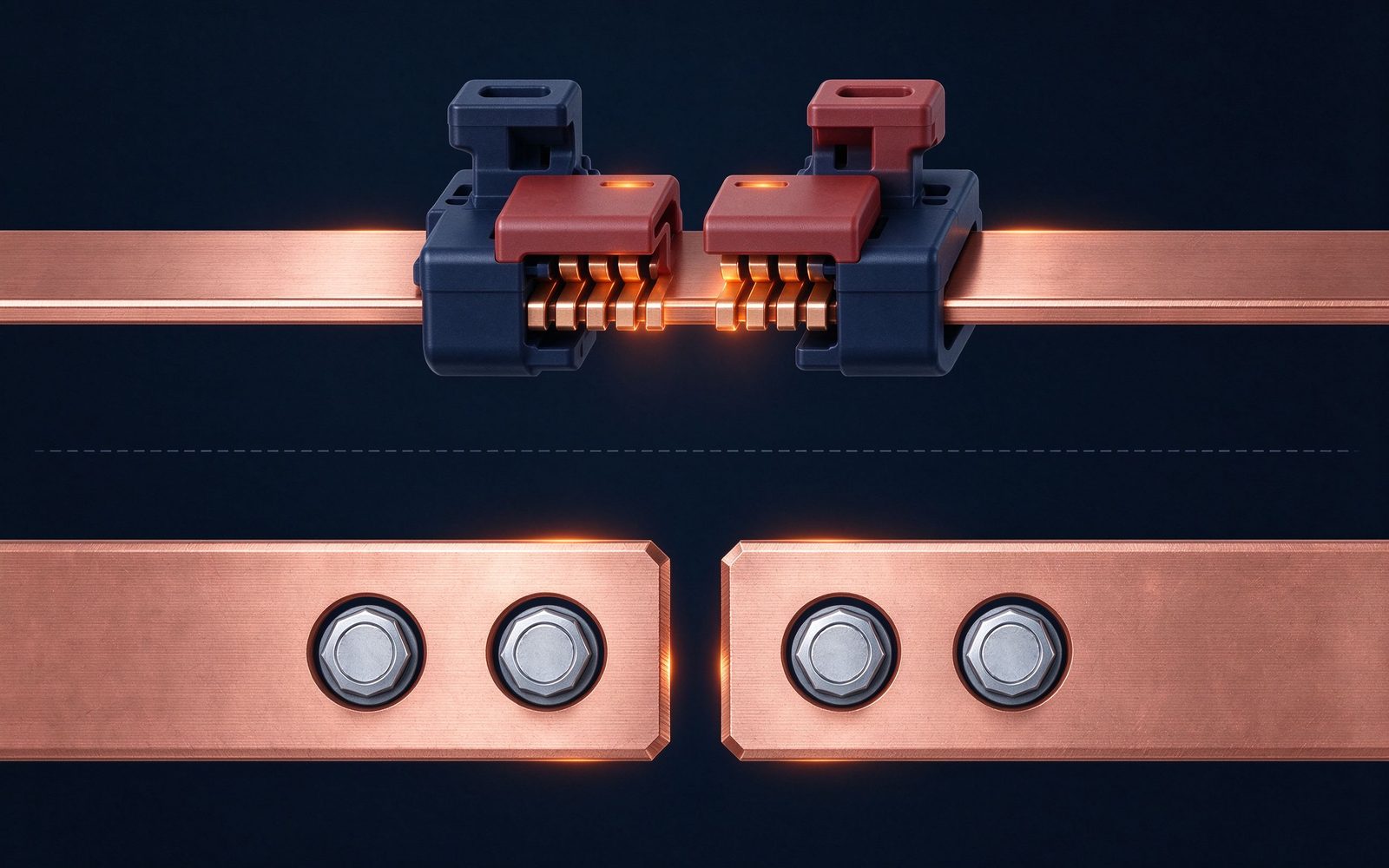
Blind-mate connectors solve a different problem: joints you cannot see during mating, because the two halves live inside a drawer push-in. The modular family comes in three frame sizes — 6.4 mm, 9.1 mm and 12.7 mm — as 2-pole and 4-pole housings, with contacts routed for individual poles or combined in parallel for a higher single-pole amperage. Terminations are flexible: crimp wire up to 4/0 AWG, threaded studs at M5, M6 or M8, or direct bus-bar termination, which is the laminated-busbar case we care about most.
| Frame size | Current at 30 °C rise (bus-terminated) | Contact resistance | Bus / termination design |
|---|---|---|---|
| 6.4 mm | 175 A | 60 µΩ | M5 thread; 25.4 × 3.2 mm copper bus |
| 9.1 mm | 265 A | 45 µΩ | M6 thread; 38.1 × 4.8 mm copper bus |
| 12.7 mm | Largest frame; up to 365 A per contact bus-terminated | Reference 45–60 µΩ class | M8 stud / crimp to 4/0 AWG |
Read the table with the rating convention in mind. The current at a 30 °C rise is the continuously usable number in typical cooling; the maximum rated capacity, up to 365 A per contact when bus-terminated, is the ceiling, not the design point. Crimp-terminated variants run lower still: the 6.4 mm frame is about 100 A at a 30 °C rise on 4 AWG, and the 9.1 mm frame about 180 A on 2/0 AWG — which is why direct bus termination is the efficient route above 175 A.
Notice the right-hand column: every frame names a specific copper bus cross-section at the contact land, 38.1 × 4.8 mm for the 9.1 mm frame at M6. That is co-design, not retrofit, and it is the point most busbar drawings miss: the bar under the contact must be as specified, because the contact and the land share the current-spreading job. In scalable low-voltage systems the same thinking adds float: the blade busbar floats relative to the receptacle to absorb cabinet tolerance buildup, lead-in chamfers self-guide the engagement, and silver plating is chosen on the retained contacts for durability across repeated insertions and minimal voltage drop.
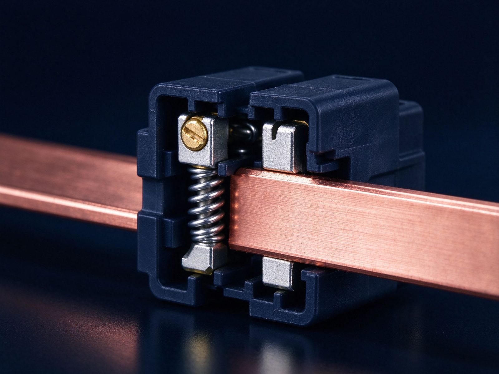
Why does contact geometry matter this much? Because current does not flow the way the drawing suggests. Even a polished, plated mating surface is microscopically a field of peaks and valleys; current actually flows only through the small touching asperities, not across the whole nominal contact area. The bigger the apparent area, the more of it is wasted.
Industry historically fought this three ways: enlarge the contacts, which makes bigger, pricier parts; raise the normal force, which means high mating friction and expensive latching hardware; and finish the surface better, which buys diminishing returns. There is also an unavoidable material compromise: pure copper is highly conductive but has no spring, so the practical spring-plus-conductor choice, a copper-beryllium or copper-tin alloy, is less conductive. Every high-current contact is negotiated inside that triangle.
The better lever is to maximize the number of discrete parallel contact points rather than enlarge or polish the area. With many junctions in parallel, the total junction resistance drops even though each individual junction is small. The engineered version uses two stacked rows of copper-alloy beams, each fingertip carrying a slight indentation that creates two contact points per finger. Measured against equivalently rated conventional connectors, the result is a 3–5× lower insertion force, a 2–3× lower contact resistance, and a proven cycle life on the order of 10,000 mating cycles — all without growing the package.
The trade to remember for your own designs is the direction of the lever. Adding parallel fingers lowers resistance and lowers insertion force at the same time; raising normal force buys resistance only by spending force, wear and latch cost. Plating closes the loop: silver over nickel on the socket and pin contacts gives low voltage drop and survives the insertions; thermoplastic insulators to UL 94 V-0 hold the beams on their pitch. Our note on busbar terminal connection options walks the terminal-side choices in more detail.
A different contact family solves the board-level end of the path: small-footprint, high-current press-fit contacts designed for press-fit installation onto busbars, printed circuit boards and cable-lug terminations. In effect, the contact turns a plain bar into a connectorized interface without any threaded hardware on the busbar face.
The family is offered in five frame sizes — 2.4 mm, 3.6 mm, 5.7 mm, 9.1 mm and 12.7 mm — in a high-current class up to 400 A, using the same multi-redundant-point geometry: two overlying rows of beams, each beam tip with a small indent giving dual contact points. RoHS compliant, low insertion force, low contact resistance, low voltage drop and low contact wear are the stated targets across the whole size span.
Why threadless mounting matters. No screws at the busbar face means no height budget spent on fasteners, and, more importantly, no threaded joint to undo under vibration — the classic slow failure in racks. Because one contact family scales from small taps to 400 A-class power positions, a single bar can carry mixed low-power and high-power tap densities with one tooling philosophy. The three terminations, busbar, PCB and lug, also mean the same contact can land on the bar edge, solder into a board, or take a cable end, which is how dense converter I/O gets built without a fastener forest. The cost argument follows: no threaded hardware at the bar face removes an assembly step and a torque checklist per position, which at hundreds of positions per cabinet is a serious line-time saving.
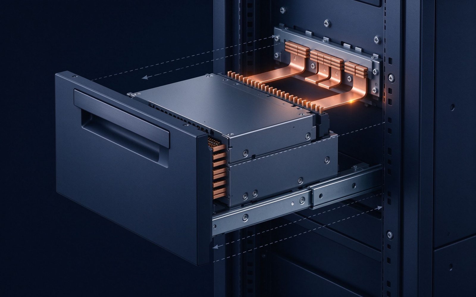
When a single blind-mate contact is not enough, the standard move is not an over-sized contact: it is parallel poles. The 2- and 4-pole housings are routable as individual circuits or combined so several poles carry one pole's current. Each contact in parallel divides the current and divides the junction resistance, and the housing stays a drawer-friendly size instead of becoming a brute-force joint.
The other half of scaling current safely is hot-swap behavior. A load-pluggable joint is rated for the current it can actually interrupt: reference clip-class figures are 200 A at 12 V open circuit and 100 A at 60 V open circuit. What makes interruption survivable is geometry, not luck: lead-in chamfers sequence the contacts so the break happens in a controlled order, and UL 1977 together with CSA C22.2 No. 182.3 specifically includes current-interruption and arcing requirements for this category. The contact material — copper-beryllium, plated silver or gold — is chosen to survive the brief make-and-break arc, and the ~10,000-cycle life number is the result of sizing the fingers and plating for the actual swap frequency.
The practical design rule is to design hot-swap around the open-circuit voltage of the bus, not its nominal voltage. A 48 VDC rack system lives comfortably inside the rated interruption window; once you climb toward higher DC link voltages, the interruption rating has to be checked explicitly, because arc energy rises fast as voltage rises. Front-end power modules in DC fast chargers are a characteristic home for this: paralleled modules, pulled and replaced under service while the station keeps running, which is exactly the duty the interruption-rated contact family exists for.
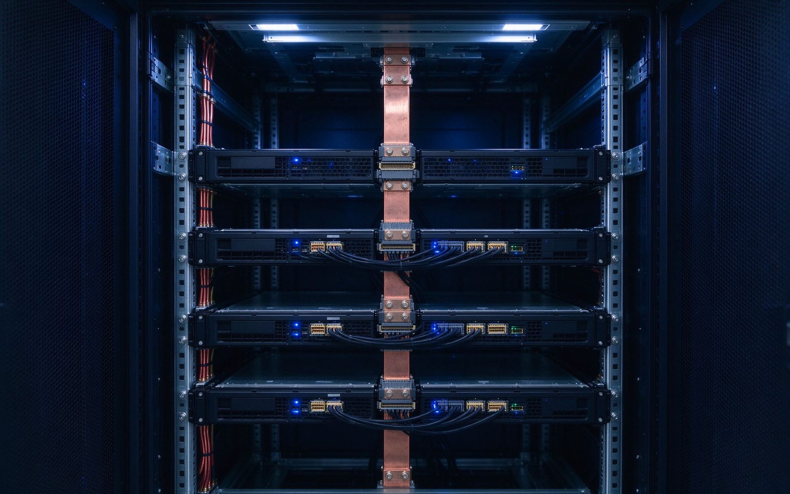
Co-design rules that keep the whole system honest:
This is where a laminated busbar manufacturer earns its keep: we build the bar around the contact land instead of bolting a connector onto a stock profile. Our power-electronics laminated busbar family runs 1–6+ conductor layers in C11000 copper, tin-plated terminals and PET, Nomex or epoxy dielectrics, and we flag contact-land geometry, plating and thermal margin in the DFM review before tooling. Every lot ships with in-house QC records — hipot, insulation resistance, dimensional, visual and continuity — so the joint you designed is the joint you receive.
Q: What is the difference between a clip connector and a blind-mate connector? A: The clip clamps onto an open-sided bar from outside, usable anywhere along its length for visible service. The blind-mate halves meet hidden inside a drawer push-in, self-aligning, for modules you cannot see or reach during insertion.
Q: How much current can a bus-to-bus joint really carry? A: Reference blind-mate frames run 175–265 A at a 30 °C rise, up to 365 A per contact at maximum rating when bus-terminated, and clip-class joints reach 400 A combined single-pole. Above that, parallel poles in one housing are the standard route rather than one oversized contact.
Q: Is a simple bolted joint still the best option? A: Bolted stud-and-lug joints remain the default for fixed, never-serviced points. Clips and blind-mate contacts win where you need arbitrary tap position, hot-swap under load, or drawer serviceability that a torque wrench cannot offer.
Q: Why not just tighten the bolt more? A: Higher normal force buys a little contact resistance at the cost of creep, relaxation and wear. Multi-finger parallel contacts reach the same low resistance at 3–5× lower insertion force and survive on the order of 10,000 mating cycles.
Q: Which standards should a bus-to-bus connection meet? A: Treat UL 1977, CSA C22.2 No. 182.3, UL 94 V-0 insulators and RoHS compliance as the baseline for power-interconnect hardware in serviceable racks; note that the standards family also covers current interruption and arcing for hot-swap duty.
Send the current profile, voltage class and installation conditions — we will size the busbar and document the calculation with your quotation.
Send the current profile, voltage class and installation conditions — we will size the busbar and document the calculation.
