A busbar sized on the fundamental current alone is already undersized the moment the load is a VFD, a charger or a UPS. Non-linear loads push harmonic current into the bar, and two effects compound: the RMS current rises above the fundamental reading, and the harmonic frequencies raise AC resistance through skin effect. The practical numbers: at 15-25% THD, busbar heating increases 8-15% beyond the fundamental-frequency calculation; at 40% THD, the extra heating reaches 25-35% (GRL Copper, 2026). This guide turns those figures into a sizing workflow - THD-based derating factors, skin-effect handling, neutral sizing for third-harmonic content, and the parallel-bar multipliers that most catalogues leave out.
A busbar sized on the fundamental current alone is already undersized the moment the load is a VFD, a charger or a UPS. Non-linear loads push harmonic current into the bar, and two effects compound: the RMS current rises above the fundamental reading, and the harmonic frequencies raise AC resistance through skin effect. The practical numbers: at 15-25% THD, busbar heating increases 8-15% beyond the fundamental-frequency calculation; at 40% THD, the extra heating reaches 25-35% (GRL Copper, 2026). This guide turns those figures into a sizing workflow - THD-based derating factors, skin-effect handling, neutral sizing for third-harmonic content, and the parallel-bar multipliers that most catalogues leave out.
A clean 50 Hz load heats a busbar in proportion to I²R at power frequency. A non-linear load - rectifier front end, VFD output stage, EV charger, UPS - draws a distorted current made of the fundamental plus higher-order components. The total RMS current is the root-sum-square of all of them:
I_RMS = sqrt(I1² + I3² + I5² + I7² + ...)
That alone lifts heating above the fundamental-only number. On top of it, each harmonic component sees a higher AC resistance than the fundamental because of skin effect, so the effective heating grows faster than the RMS figure suggests (Bepto, 2026).
Field practice gives workable brackets. At 15-25% total harmonic distortion, busbar heating runs 8-15% above the fundamental calculation; at 40% THD the additional heating hits 25-35% (GRL Copper, 2026). A typical VFD load with 25% THD has RMS current about 3% above the fundamental alone - modest - but the harmonic components also raise AC resistance, and the combined derating is what actually bites (Bepto, 2026).
Simplified THD-based factors: 1.00 below 5% THD, 0.97 at 5-15%, 0.94 at 15-30%, 0.90 above 30% (Bepto, 2026). These are sanity checks, not replacements for a measurement-based calculation.
At 50 Hz, skin depth in copper is around 9.4 mm, so a bar thinner than about 10 mm is barely affected at the fundamental (A&J Link, 2026). The problem is the harmonics: a 5th harmonic at 250 Hz has skin depth roughly a third of the 50 Hz value, a 13th at 650 Hz about a fifth. Current crowds to the surface, effective resistance rises, and the harmonic components heat the bar disproportionately to their RMS share.
This is the physics that makes multiple thin layers outperform one thick layer: a laminated busbar splits the conductor into layers near the surface, recovering current-carrying capacity that a single thick bar loses to skin effect.
A practical formula used for conductors in harmonic service ties THD to a derating factor: k_H approximates 1/sqrt(1 + 0.01·h²·k_skin), where h is THD in percent and k_skin captures the AC-resistance growth (Bepto, 2026). For 30% THD with typical skin effect, k_H lands near 0.94 - a 6% cut in safe capacity that most specifications omit.
On a concrete example: a 1,250 A-rated bushing serving 30% THD industrial load derates to about 1,175 A. If your plant feeds VFDs and rectifiers, the same arithmetic applies to every busbar feeding them.
Triplen harmonics - the 3rd, 9th, 15th - add arithmetically in the neutral instead of cancelling, because they are zero-sequence. In a 3-phase 4-wire system serving single-phase loads, the neutral can carry more than phase current when triplen content is high (GRL Copper, 2026).
Neutral busbar sizing has to follow the neutral current, not the phase current. If the neutral busbar is omitted from the drawing or sized as a fraction of the phase bar, harmonic-heavy buildings find the neutral bus running hot years before anyone measures it.
The classic trap: two bars per phase do not carry twice the single-bar rating. Proximity effect and uneven sharing cut the multiplier to 1.6-1.8 times the single bar; three bars give roughly 2.2-2.5 times (busbar rating practice, 2026). Above about 1,500 A per phase, parallel bars need explicit derating: 0.95 for two bars, 0.90 for three, 0.85 for four or more, with spacing at least the bar thickness to limit airflow restriction (GRL Copper, 2026).
In harmonic duty the situation is worse, because proximity effect compounds with skin effect. A laminated or multi-bar arrangement designed with spacing and phasing in mind recovers capacity that a naive parallel stack loses.
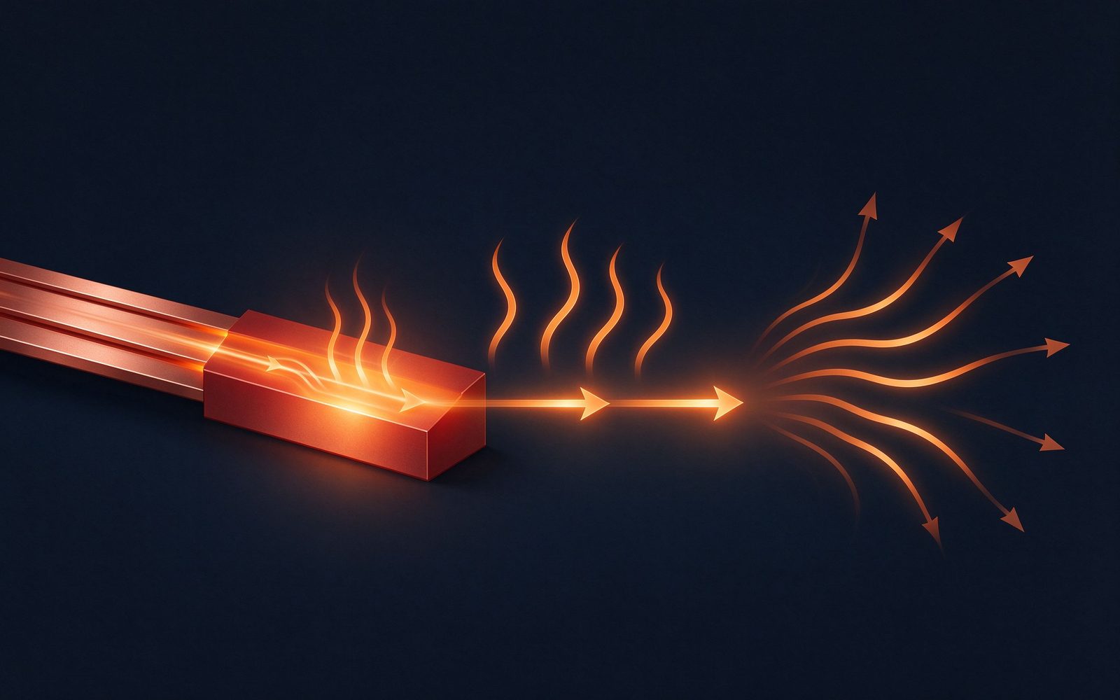
Harmonic derating never applies in isolation. Ambient temperature: a bar rated at 40 °C ambient carries roughly 80-85% of that rating at 55 °C (busbar derating tables, 2026). Enclosure: ventilated cabinets allow about 90% of open-air rating, sealed enclosures drop to 70% or less. Altitude above 2,000 m cuts convection further.
The compounding is the message: a 1,000 A bar in a sealed cabinet at 50 °C ambient serving a 25% THD drive load can end up effectively rated well below half its nameplate. Derating factors multiply, and none of them is optional.
For design-stage sizing, the cleanest method is a harmonic load factor applied on top of the thermal calculation: 1.15-1.35× for installations with significant harmonic content - VFD plants, data centres, charging hubs (GRL Copper, 2026). Size the bar for the fundamental load, multiply by the harmonic factor, then apply the environment derating.
Alternatively, use the measured or expected harmonic spectrum directly: compute I_RMS from the actual order distribution, apply frequency-dependent AC resistance per harmonic, and sum the heating. Spectrum-based sizing is more accurate and is the right method when THD is high or the spectrum is known from commissioning data.
For a given cross-section, a wide thin bar dissipates more heat than a narrow thick bar: a 100×10 mm bar has a perimeter-to-area ratio of 0.22 mm⁻¹ against 0.14 mm⁻¹ for a 50×20 mm bar of the same area - over 35% more cooling surface (GRL, 2026). That is why standard bars rarely exceed 20-25 mm thickness; engineers add width or go parallel instead.
The same logic helps harmonics: thin layers keep more conductor within the skin depth at harmonic frequencies, so wide-and-thin or laminated constructions retain more capacity under distorted loads than a single thick bar.
Calculation gets you to a candidate bar; commissioning confirms it. Thermal imaging at full rated load - with the real harmonics running - is the most reliable verification for harmonic-heavy circuits (GRL Copper, 2026). Measure phase and neutral temperatures at the joint faces, not just the bar surface, because connections are the hot spots.
Where the design is tight, a temperature-rise test on the actual assembly with a representative current waveform beats both calculation and imaging. IEC 61439-style verification accepts calculation, testing or a combination; the responsibility for the result sits with the manufacturer (busbar assembly practice, 2026).
The two load classes driving harmonic-aware busbar design in 2026 are the ones growing fastest: data-centre power distribution and EV charging. Both are rectifier-dominated - switch-mode PSUs on one side, charger power modules on the other - and both push THD toward the top of the brackets above.
For a data-centre busway or a charger DC-link busbar, the sizing conversation should start with the expected harmonic spectrum, not the nameplate current. Our DC power and charging market notes cover the demand side; this guide covers the arithmetic.
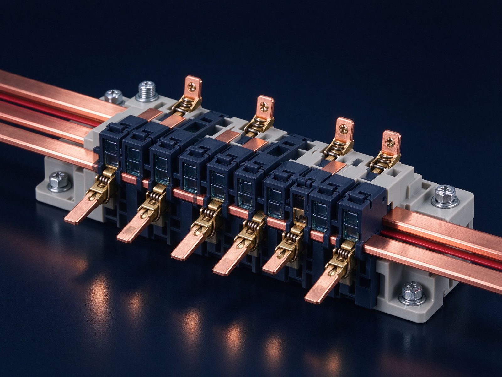
THD is a load property, not a busbar property - it changes with load level, power quality and what the site adds later. A power-quality analyser at the busbar position, run across a full load cycle, is the honest basis for the derating factor. One afternoon of measurement is cheaper than one year of a hot neutral.
Keep the measurement in the commissioning file: the THD snapshot, the derating factors applied, and the final bar cross-section. When the site grows - more drives, another charger bank - the file tells you whether the busbar still has headroom before it becomes a problem.
The retrofit question comes up constantly: a busway or switchgear busbar installed for a linear load now feeds VFDs, and the bar runs hot. The options in order of cost: measure first (THD and thermal imaging confirm the diagnosis); rebalance loads across phases to cut triplen neutral current; improve ventilation or add fans to lift the enclosure derating; and only then consider replacing the bar with a wider, thinner or laminated equivalent.
Retrofitting a laminated busbar into an existing cabinet is a mechanical and dielectric exercise as much as an electrical one - clearances, supports and terminations all change. That is a DFM conversation, and it is where the geometry rules above earn their keep.
SHANYUAN sizes busbars for the real load: when a customer's application is VFD, charger, UPS or rectifier duty, we apply the harmonic load factor and the environment derating before confirming a cross-section, and we document the assumptions in the quotation. C11000 copper, 1-6+ layers, 30 °C-rise rating basis - the same discipline across every product family.
Send the current profile, THD or harmonic spectrum, ambient and enclosure details; our engineers will return a sized cross-section with the derating factors stated, within one business day.
Skin depth is the number that explains why laminates win under harmonics. In copper at 50 Hz it is about 9.4 mm; at 250 Hz roughly a third of that; at 1 kHz about 2 mm. A single 25 mm-thick bar at 1 kHz uses a thin shell of its cross-section, while a stack of 2-3 mm layers keeps most of the conductor within skin depth at every harmonic that matters.
That is the engineering argument for laminated construction in converter and charger duty - not just low inductance, but harmonic capacity. If the load spectrum is rich in the 250 Hz-2 kHz range, the laminated bar's advantage compounds.
Data-centre power demand is forecast to roughly double between 2024 and 2030 - from about 415 TWh to about 945 TWh (IEA, 2026) - and every watt passes through rectifiers, UPS and switchgear. The busway and busbar designs serving that load are sized under exactly the harmonic rules in this guide, with the load factor applied before the copper is ordered.
For the busbar supplier the consequence is simple: the fastest-growing application class is also the most harmonic-heavy. The sizing arithmetic in this guide is not academic for a data-centre or charging programme; it is the difference between a bar that runs at 60 °C and one that runs at 90.
Harmonic limits are codified, which gives the sizing conversation a legal floor. IEC 61000-2-4 and IEEE 519 set compatibility and planning levels for voltage and current distortion; a site that stays within IEEE 519's current THD limits still may not stay within a busbar's thermal comfort zone, because the limits are for the system, not for the busbar.
The practical reading: measure the actual current distortion at the busbar position, apply the derating factors, and document the decision. A power-quality standard is the starting point of the conversation, not the answer to it.
The end of the sizing chain is evidence: a temperature-rise report at the real load and waveform. Ask for it whenever the installation is harmonic-heavy, tightly derated, or inside a sealed enclosure - precisely the cases where calculation error is most expensive.
Our busbar quotations for VFD, charger and UPS duty include the rating basis and derating assumptions, and we can supply a temperature-rise report on the actual assembly where the application justifies it. That is the difference between a catalogue rating and an engineered one.
The neutral busbar is the one everyone undersizes. In a 3-phase 4-wire system with single-phase loads and switch-mode supplies, triplen harmonics add in the neutral, and the neutral current can exceed any phase current. The classic symptom is a neutral bus and neutral cables running warm while the phases look fine.
The fix is a specification line, not a mystery: state that the neutral busbar is sized for the neutral current, computed from the harmonic spectrum, not as a fraction of the phase bar. On retrofit projects, measure the neutral current with a clamp analyser before touching the busbar - the data decides whether the bar or the loading is the problem.
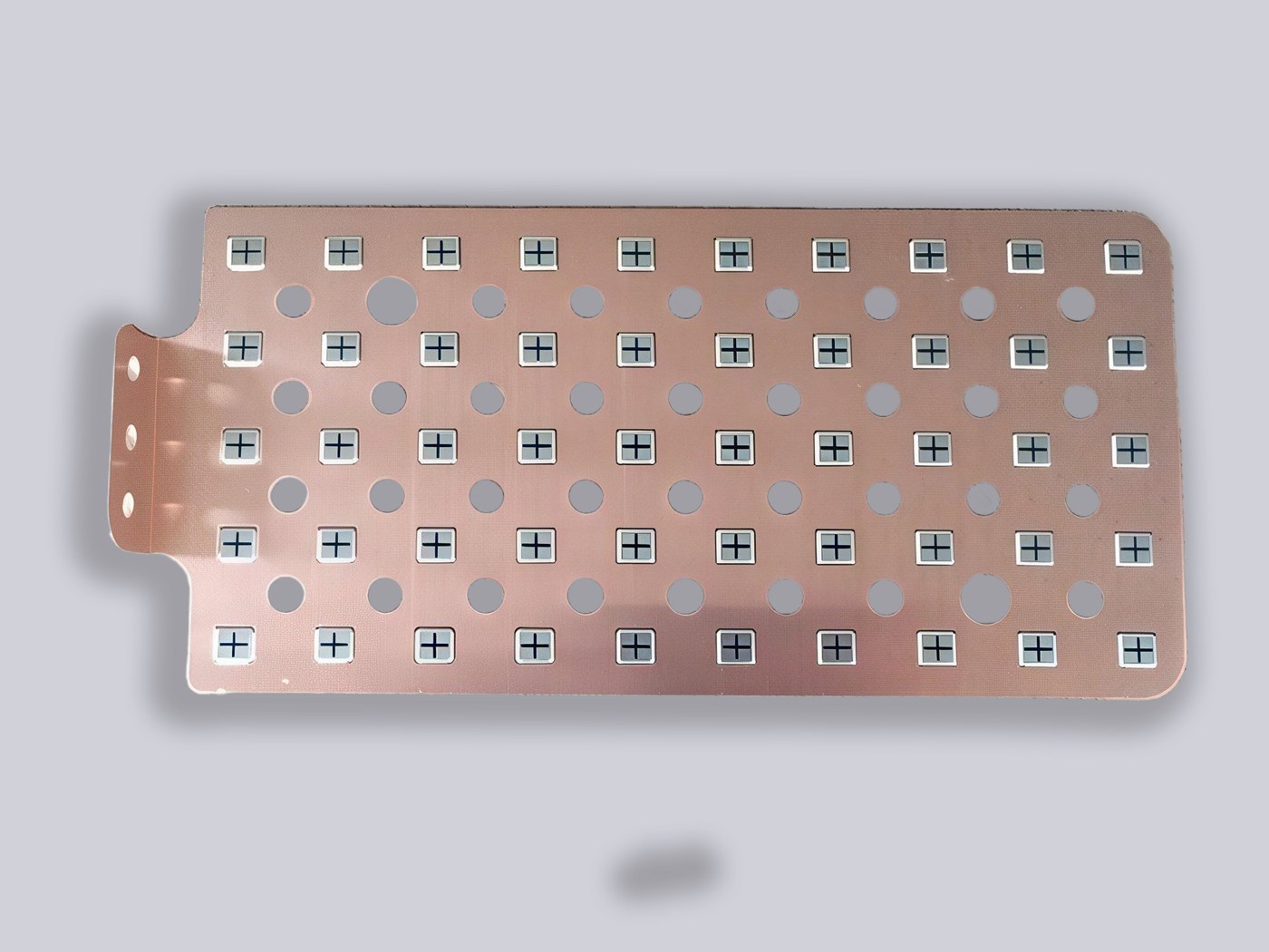
Copper busbar current rating is not a single number. It is a starting ampacity adjusted by
Read articleA busbar's rating is not a lookup — it is a calculation. Temperature rise is the real limi
Read article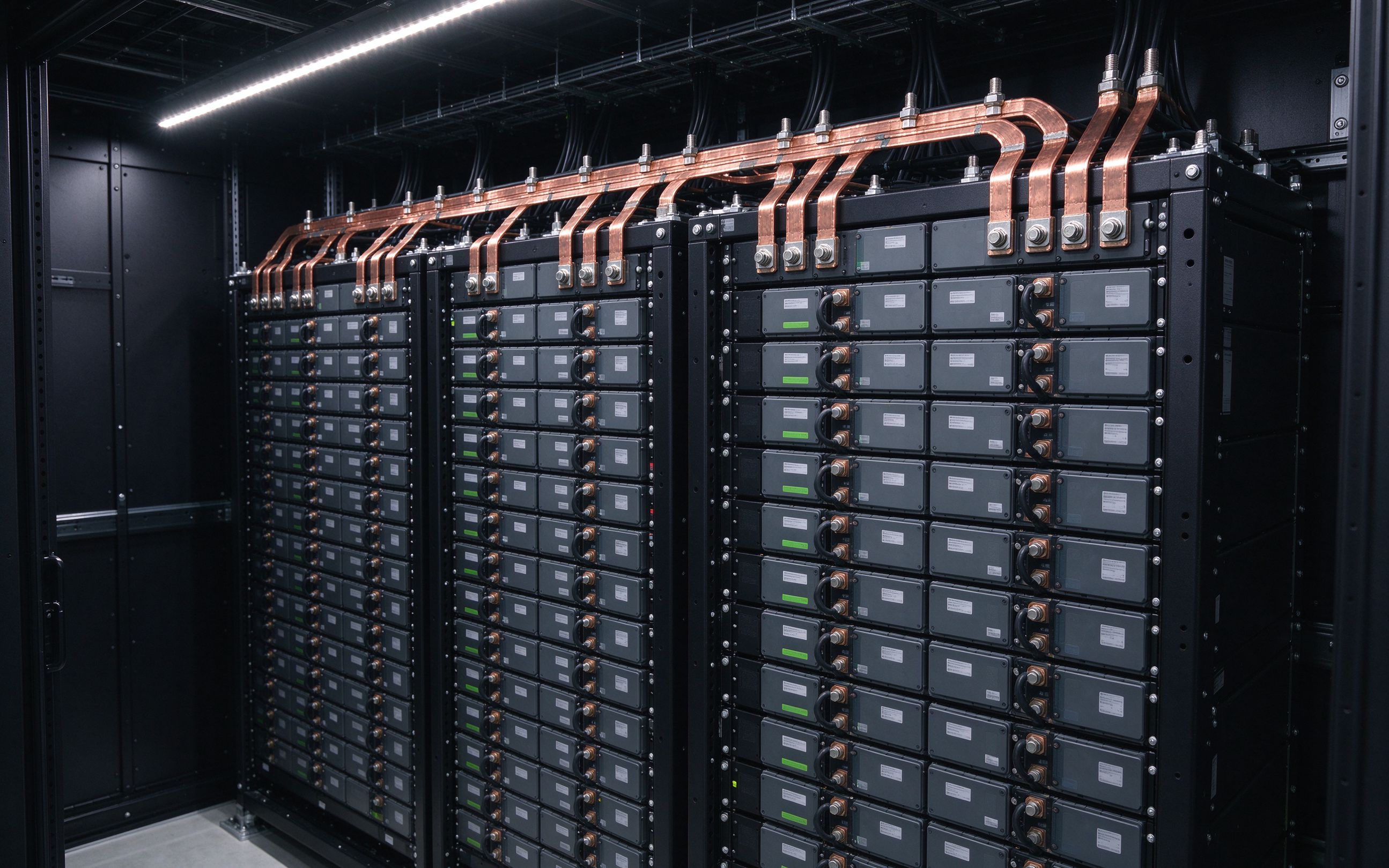
AI racks move from 140 kW to 1 MW by 2027, and the industry answers with 800 VDC distribut
Read articleSend the current profile, voltage class and terminal types — our engineers reply within one business day.
