Mon–Fri 9:00–18:00 · CST (UTC+8) · Shandong, China
News · Mechanical Design

Busbar Bolted Joints in Vibration: Preload, Thermal Cycling and Mechanical Design

Most busbar failures are not electrical - they are mechanical, and they start at a bolted joint. Vibration relaxes the joint by micro-slip; thermal cycling fatigues it by repeated strain; and the two mechanisms demand different responses. This guide sets out the mechanical design of busbar bolted connections: what preload does, why washers are not optional, how coefficient-of-thermal-expansion mismatch steals clamping force, and how the rules change for rail-grade vibration per IEC 61373.

By SHANYUAN Mechanical Design Engineering Team Mechanical Design Technical Note

Most busbar failures are not electrical - they are mechanical, and they start at a bolted joint. Vibration relaxes the joint by micro-slip; thermal cycling fatigues it by repeated strain; and the two mechanisms demand different responses. This guide sets out the mechanical design of busbar bolted connections: what preload does, why washers are not optional, how coefficient-of-thermal-expansion mismatch steals clamping force, and how the rules change for rail-grade vibration per IEC 61373.

1. What a Bolted Busbar Joint Actually Carries

A bolted joint in a current path has two jobs at once. Electrically, it must hold contact pressure so the interface resistance stays low and stable; mechanically, it must hold preload so the joint survives vibration, temperature cycling and decades of service. The two jobs are coupled: when preload decays, contact pressure falls, resistance rises, temperature rises, and the loop accelerates toward failure.

The design starting point is therefore the preload target - the clamping force the joint must hold - not the bolt size. Everything else, from washer selection to torque specification, serves the preload.

2. Preload: Setting and Verifying

Preload is set by torque, verified by angle or stretch. Torque-only control has wide scatter (typically +/-25% with lubrication variation); torque-plus-angle or direct stretch control tightens the distribution to a few percent. For busbar joints the practical choice depends on the program: high-reliability rail and aerospace practice favours angle control; industrial cabinets routinely use torque with a defined lubrication and fastener class.

The terminal connection guide documents the torque ranges SHANYUAN applies to M6/M8 stud connections with the corresponding preload estimates.

3. Vibration Loosening: The Micro-Slip Mechanism

Vibration loosens a bolted joint by micro-slip at the thread and bearing interfaces. Each load cycle produces a small relative motion; over millions of cycles the nut 'backs off' even when the bolt appears tight. The controlling parameter is the interface friction and the joint's ability to stay below the slip threshold.
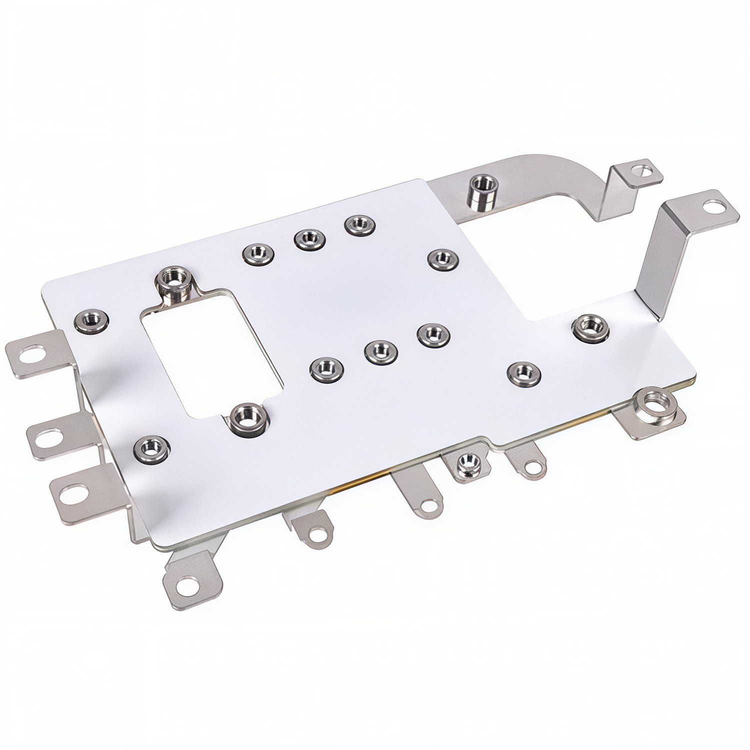
Bolted busbar bracket with stud terminals

Higher preload raises the slip threshold and suppresses the vibration response of the connected structure - a study from Nanjing University of Aeronautics and Astronautics shows that increasing bolt preload significantly reduces the vibration amplitude of the connection by raising equivalent stiffness and delaying slip onset (Vibration, Testing and Diagnosis, April 2026). The design response is unambiguous: preload is a vibration-control parameter, not a bolt-sizing afterthought.

The vibration test plan has one more element worth stating: the test is run at temperature, not at ambient. A busbar joint that passes the vibration spectrum at 20 °C may fail at operating temperature, because the preload window shifts with the thermal state and the plating's compliance changes. Rail qualification practice therefore runs vibration and thermal cycling as combined tests where the service duty demands it - the joint is cycled hot and vibrated, and the torque and resistance are checked at the end of the combined profile.

The combined test also exposes the interaction between the two failure mechanisms. Vibration loosening and thermal relaxation both reduce contact pressure, and their effects add: a joint that has crept at temperature is closer to the slip threshold when the vibration spectrum arrives. The design margin that survives the combined test is the margin that survives service, which is why the combined profile is the qualification gate for traction and high-cycle industrial joints.

4. Washers: Why They Are Not Optional

Plain washers spread the bearing load and protect the plating; spring washers and Belleville (disc spring) washers add elastic travel that maintains clamping force as the joint relaxes. The distinction matters: creep in plated contacts relaxes the joint by small, slow strains, and the remedy is spring travel that converts the relaxation into reduced spring force rather than lost contact pressure (A&J Link, September 2026). Belleville washers stacked in series provide long elastic travel in a short space - the standard tool for kiloamp bolted joints where the joint must stay electrically stable through thermal cycling.

On SHANYUAN assemblies, the washer set is specified per joint duty: plain + Belleville for high-current module connections, plain + split for lighter terminals.

5. Thermal Cycling Fatigue vs Creep

Thermal cycling fatigue and creep are different mechanisms that get confused. Creep is the slow permanent deformation of the plated contact under sustained load and temperature - mitigated by spring travel (Belleville washers). Thermal cycling fatigue is the repeated expansion and contraction of the joint as load cycles; each cycle imposes a small strain on the interface, and over thousands of cycles that strain can loosen the joint or initiate cracks in the plating (A&J Link, 2026). The response is to keep the stress range low enough that the joint remains elastic throughout the cycle - which means controlling the joint's stiffness, the CTE mismatch and the thermal gradient.

Both mechanisms reward the same design: enough elastic compliance to absorb relaxation without losing contact pressure, and a stress range small enough to stay elastic.

The thermal cycling evidence deserves a measurement note. The standard qualification is a temperature cycle across the operating range - for a traction converter, typically from cold soak to the hot operating point - with contact-resistance logging at the temperature extremes and at room temperature between cycles. The acceptance criterion is that the joint resistance returns to the first-article value within a small band; a joint that drifts upward cycle over cycle is a joint that is relaxing, and the drift rate is the design's early warning.

The same cycling data feeds the maintenance interval. A joint whose resistance is stable across 5,000 cycles can be inspected on the train's normal service interval; a joint that drifts needs a shorter interval or a design change. The documentation chain - first-article values, cycling log, maintenance thresholds - is what turns the test from an engineering exercise into a fleet management input.

6. CTE Mismatch: The Quiet Preload Thief

Bolts and the components they clamp are usually different materials with different coefficients of thermal expansion. When the assembly heats, each part grows at its own rate: if the clamped members expand more axially than the bolt, preload rises; if the bolt grows more, preload falls (Velocity Bolting, July 2026). A copper busbar clamped by a steel bolt is the classic case - copper's CTE is roughly 60% higher than steel's, so the temperature swing redistributes clamping force between the copper and the bolt, and transient gradients at startup make it worse (the bolt heats slower than the busbar and sees a transient tension swing).

Steel bolts on copper busbars work because the elastic modulus and length ratios keep the system stable, but the CTE check belongs in the design file, and aluminium-busbar joints need extra care because aluminium's CTE is higher still.

7. The Unconstrained-Expansion Calculation

The starting calculation for any bolted joint under temperature is the free expansion: delta-L = alpha-L x L x delta-T, where alpha-L is the coefficient of thermal expansion, L the length and delta-T the change (Sandia National Laboratories, bolted joint design guideline). The unconstrained part expands freely; a constrained joint converts that expansion into a change in clamping force. In a T-type clamp or a bolted busbar lap joint, the thermal expansion at the contact interface is constrained by the bolt, generating an elastic reaction force - thermal pressure - that adds to or subtracts from the mechanical preload (PLOS ONE, 2026, multiphysics-coupled preload solution for T-type clamps).

The practical output is a preload window: at minimum temperature the joint must still have contact pressure; at maximum temperature the bolt stress must stay below yield.

8. Rail-Grade Vibration: IEC 61373

Rail equipment is qualified to IEC 61373, with random vibration spectra far more severe than a stationary industrial cabinet. A busbar in a traction converter sees the vehicle's broadband vibration through millions of cycles, at operating temperature, for its whole life. The qualification approach combines design margin (preload above the slip threshold with margin), test (random vibration per the standard's category for the mounting position), and periodic inspection of the torque on maintenance intervals.

For suppliers, the deliverable is a documented joint design - torque, washer set, plating, and the vibration test evidence - that the OEM can carry into the vehicle's qualification file. Traction converter programs apply exactly this discipline to their DC-link busbars, as covered in our SiC traction converter article. Our quality page describes the factory-side inspection chain that supports it.

9. Plating and Friction Factor

Torque-to-preload conversion depends on the friction factor, and the friction factor depends on plating. A silver-plated contact face and a nickel-plated thread have different friction behaviour than bare copper; lubrication changes it further. The practical rule: define the plating AND the lubrication in the torque specification, and verify the preload by angle or stretch on first articles rather than assuming the torque table is right.

SHANYUAN's plating and corrosion guide covers finish selection; the mechanical desk then maps finish to friction factor and torque for each joint.

10. Joint Design for Maintenance

A bolted busbar joint is a service item, not a sealed component. The design should make torque re-check possible: accessible heads, defined torque values on the drawing, and space for a calibrated torque wrench. Maintenance intervals for rail and industrial equipment include busbar torque inspection, and the manufacturer's documentation should state the intervals and the values. A joint that cannot be re-torqued without dismantling the stack is a design error that shows up at the first major service.

11. The Multi-Physics Check

Modern practice closes the loop numerically: the electromagnetic loss map feeds the thermal solve, the temperature field feeds the CTE expansion, and the expansion feeds the preload change, which feeds the contact resistance - and the loop closes back on the losses. T-type clamp preload studies now solve exactly this multiphysics coupling to compute the thermal pressure in the joint (PLOS ONE, 2026). For critical joints in traction and kilowatt-class DC links, this closed-loop check is the difference between a joint that survives and one that fails at the first summer peak.

12. Design Rules Summary

The rules in one place: set a preload target from the contact-resistance requirement, not from the bolt catalogue; use angle or stretch control on critical joints; add spring travel (Belleville) for creep and thermal relaxation; run the CTE check on every mixed-metal joint; qualify against the actual vibration spectrum (IEC 61373 for rail); define plating, lubrication and torque together; design for re-torque; and close the multiphysics loop on critical joints. SHANYUAN applies these rules to every terminal configuration - M6/M8 studs, blade terminals and welded tabs - and documents the joint design with the part. Start from our custom busbars page or the connection guide.

The closing rule is organisational rather than technical: the joint design file is a living document. It starts with the preload calculation, grows with the first-article torque calibration, gains the vibration and cycling evidence, and keeps a column for the maintenance data from service. A joint design that is treated as finished at the drawing stage is a design that will be re-litigated at the first failure; a joint design that is treated as a data set grows more reliable with every fleet and every plant year.

13. Joint Resistance Monitoring in Service

A bolted busbar joint is monitored in service the same way the plant monitors everything else: by temperature. An IR survey or a fixed thermocouple on a suspect joint catches the resistance rise that precedes failure - a hot joint is a joint losing contact pressure. The survey interval should follow the design: joints with Belleville compliance and conservative preload run cool for decades; joints with marginal preload show up in the first year.

Stamped busbar bracket with stud terminals and mounting ears

The maintenance record is the feedback loop: torque re-check values, IR survey data and plating condition at overhaul tell the engineering team whether the joint design is right for the duty. For fleet and plant programs, that data set is worth more than the original calculation.

14. Aluminium Busbar Joints: The CTE Special Case

Aluminium is the harder joint design. Its CTE is higher than copper's, its surface oxide reforms within minutes of cleaning, and its creep at temperature is faster - three reasons bolted aluminium joints are specified with bimetal or plated interfaces, larger contact area and more elastic compliance. The CTE mismatch between an aluminium busbar and a steel bolt is the largest of the common pairings, so the preload window is the tightest.

The practical rules: use plated aluminium contact faces (tin or nickel), specify the washer stack for elastic travel, and document the preload window with both temperature extremes. For the material comparison in full, the copper vs aluminium guide covers the conductor-side trade-offs.

15. Testing: What to Measure and How

The qualification evidence for a bolted busbar joint has four parts. Vibration testing per the actual spectrum (IEC 61373 for rail, or the machine's measured spectrum for industry) with torque measurement before and after; thermal cycling across the operating range with contact-resistance logging; a torque-angle calibration on first articles to set the production torque; and a destructive or semi-destructive check of a percentage of joints to confirm the preload landed inside the window. Each test answers one question: does the joint hold?

The test plan belongs in the program file before production, and the results become the maintenance baseline. A joint design without the evidence is a hypothesis.

The testing section closes with a calibration note. Torque wrenches drift, lubricants change batch, and fastener coatings age on the shelf; the torque-to-preload relationship that was calibrated at program start is not guaranteed at program end. The discipline is to recalibrate the joint setup whenever any element changes - fastener batch, coating, lubricant, washer set - and to re-verify the preload window on first articles of each batch. The maintenance data from service then validates the calibration in the real environment, which is the loop that keeps a joint design trustworthy for the life of the equipment.

16. Worked Example: An M8 Module Joint

A battery-module or converter-terminal joint on M8 studs, silver-plated faces, with a Belleville stack, carries about 3.2 kN preload at a controlled torque with angle verification. At 125 °C busbar temperature, the copper-stack expansion adds roughly 0.1-0.2 kN to the clamp while the fastener's own expansion subtracts a share; the window stays above the 1 kN contact-pressure floor and below the bolt's yield. Over 10,000 thermal cycles the Belleville travel absorbs the plating creep, and the contact resistance measured at maintenance stays within a few percent of first-article values.

That is the pattern the design rules are trying to produce: a joint whose electrical performance is a manufactured property, not a maintenance surprise.

17. Fastener Grades and Coatings

Fastener selection is part of joint design. Property class matters: a higher-grade bolt carries more preload for the same size, which widens the preload window; but the yield point and the tightening method must match the target. Coatings change the friction factor and the corrosion behaviour: zinc-nickel or zinc-flake coatings hold torque consistency better than bare zinc in humid service, and the friction factor shifts with the coating and its lubrication, which is why the torque table is only valid for the exact fastener finish and lubricant state it was calibrated with.

For a busbar joint, the terminal material (copper or aluminium), the plating and the fastener coating form one friction system. Changing any one of them changes the torque-to-preload relationship - a detail that shows up as a loosening rate change on the vibration rig.

18. Field Failure Forensics

When a bolted busbar joint fails in service, the forensic examination answers a short list of questions. Was the preload within the window at installation and at the last inspection? Was the contact pressure lost to vibration, creep or CTE swing? Was the plating intact or cracked at the contact edge? Was the temperature excursion consistent with the documented rise, or was the joint overloaded by sharing imbalance elsewhere? Each answer points at one design variable - and each variable is documented in the joint file or it is not.

The value of the discipline is that failures become data, not surprises. A joint design with a preload window, a washer set, a plating spec and a maintenance record produces a forensics story that ends in a design update; a joint without the file produces a blame discussion.

FAQ

Frequently asked questions

Why do bolted busbar joints loosen in vibration?
Micro-slip at the thread and bearing interfaces lets the nut back off over millions of load cycles. Higher preload raises the slip threshold and suppresses the vibration response of the connection.
Should I use Belleville washers on busbar joints?
Yes for high-current joints subject to thermal cycling: the elastic travel maintains clamping force as plated contacts creep, keeping contact pressure and resistance stable.
Does thermal expansion change bolt preload?
Yes - copper and steel have different CTEs, so a temperature swing redistributes clamping force. The design must keep preload above the minimum contact-pressure point and bolt stress below yield across the operating range.
Related

Continue reading

Reference

Battery Busbars

Open
Reference

Power Electronics Busbars

Open
Reference

Laminated Busbar Design Guide

Open
Reference

Partial Discharge in Laminated Busbars: Causes, Testing & Design

Open
Reference

Low-Inductance Busbar Design: Principles & Layout Rules

Open
Reference

Busbar Thermal Management: Temperature Rise, Cooling & High-Temperature Dielectrics

Open
Reference

Copper vs Aluminum Busbar Conductors: Selection Guide

Open
Reference

Flexible Laminated Busbars: Vibration, Thermal Expansion & Design Rules

Open
Reference

Quality & Testing Process: Documented QC Per Laminated Busbar Lot

Open
SHANYUAN Mechanical Design Engineering Team Rizhao Shanyuan Electronic Components Co., Ltd. — laminated busbar manufacturer, Shandong, China. Engineering notes reviewed against our production process and DFM records.

Designing a busbar for this application?

Send the current profile, voltage class and terminal types — our engineers reply within one business day.