How power moves from the supply to the loads decides cabinet reliability: voltage drop, heat, fault propagation and service time. This guide compares hard-wired, modular-rail and laminated distribution, and lays out the n+1 redundancy and hot-swap principles we apply to every busbar design.
Every converter, server shelf and charger cabinet starts the same way: a bulk supply somewhere, and a stack of loads somewhere below it. Everything in between is power distribution, and the method you choose shapes what happens next: how much voltage is lost along the way, where heat appears, how a fault propagates, and how long it takes to swap a module. Distribution architecture matters more as the bus voltage falls. At 48 VDC, a few hundred micro-ohms of joint resistance is a measurable voltage drop and a real heat source; at 400 VDC the same resistance is a rounding error. That is why 48 VDC telecom shelves, rack distribution in data centers and board-level rail schemes treat the distribution path as a designed component rather than a wiring afterthought.
Three generic architectures compete for the job. Discrete hard wiring runs fixed lug-to-lug cables, cheapest for two fixed points but slowest to reconfigure. A modular plug-in rail lets loads tap anywhere along a live bar, which is what makes scalable, serviceable cabinets possible. Laminated busbars merge several circuits into one insulated stack, which is what makes dense, low-inductance power units possible. None of them wins outright; each owns a corner of the design space, and most real cabinets end up using more than one.
The trend that keeps raising the stakes is power density. Converter stages and rack electronics pack more current into the same cubic volume every generation, and the distribution path has to keep up without adding joints, heat or downtime. A distribution architecture chosen casually on the first project turns into a thermal and rework budget on the second. This guide walks the comparison end to end: the numbers behind a reference modular rail, the laminated PDU that replaced a drawer wiring harness, a live 48 VDC (n+1) redundant installation, and the design principles that turn the architecture into uptime. If laminated construction is new to you, start with our laminated busbar design guide before the architecture choices, because every distribution decision here ends at a stack geometry.
The honest comparison is not which method is best, but which one fits the change rate of your loads. Fixed, slowly changing equipment leans on wired distribution; equipment that grows by adding modules leans on rails; equipment that packs circuits into a sealed unit leans on laminates.
| Aspect | Hard-wired point-to-point | Modular plug-in rail | Laminated busbar stack |
|---|---|---|---|
| Tap points | Fixed at design time; every new load means new wire | Anywhere along the live rail length | Fixed by geometry; integrated connector interfaces |
| Interface resistance | One lug joint per run | Small, reference ≤0.2 mΩ per tap | Negligible in the bar; small at contact lands |
| Inductance | High, loop-dependent | Reference ~500 nH/m on the rail | Lowest; stacked planes cancel flux |
| Service / rework | Slowest; rewire to change | Fastest; modules plug and unplug | Blind-mate drawer interfaces; no field rewiring |
| Best fit | Two fixed points, steady load | Scalable, serviceable cabinets | PDUs, converters, dense electronics |
Read the inductance row together with the service row. A wired harness looks cheap on the bill of materials until the fifth engineering change, and a laminated stack looks exotic until you count the hundreds of terminations it replaces. The densest modern electronics, inside PDUs and converter enclosures, converge on the laminated side; the most service-heavy infrastructure, such as data center rack distribution, converges on the rail side. Cabinet design is usually the negotiation between the two: rails on the outside for serviceability, laminates on the inside for density, and a bolted or clipped interface where they meet.
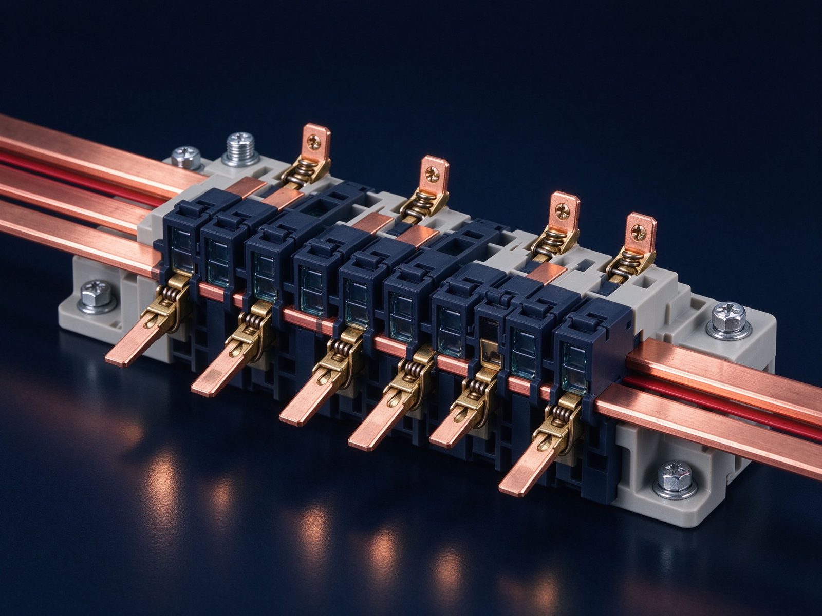
A modular power-distribution rail is a hybrid: a linear busbar with a connector contact system built into its face, sitting between a solid bar and a connector system. Reference design targets are the 200 A continuous class, built as a two-conductor double rail so two potentials are carried side by side, up to 600 VDC operating, with a 1500 VDC / 1 minute dielectric to ground and insulation resistance of at least 5×10⁹ Ω at 500 VDC.
The conductor is C11000 copper at about 99% IACS conductivity, resistivity around 1.71 µΩ·cm. The contact system uses formed louver contacts along the rail, rated at a reference 50 A per linear inch of tap density, with the interconnect resistance between a mating blade and a rail louver held to ≤0.2 mΩ. Rail inductance is about 500 nH per meter — low, but deliberately not the point of the part; the point is serviceability.
Length is modular rather than fixed: the rail builds from 6-inch units daisy-chained from 6 inches to 6 ft, ordered in 6-inch (about 154 mm) increments, so a 12-inch shelf detail and a 6-ft vertical trunk share one part family. The cable end of each tap handles 12 AWG to 4 AWG, with locking by squeeze-to-release finger clips or a jack-screw, keyed housings for polarity, and front- or rear-mount options. A 750 A class version exists in single- or dual-rail form, any length to 6 ft, for the heavier trunk.
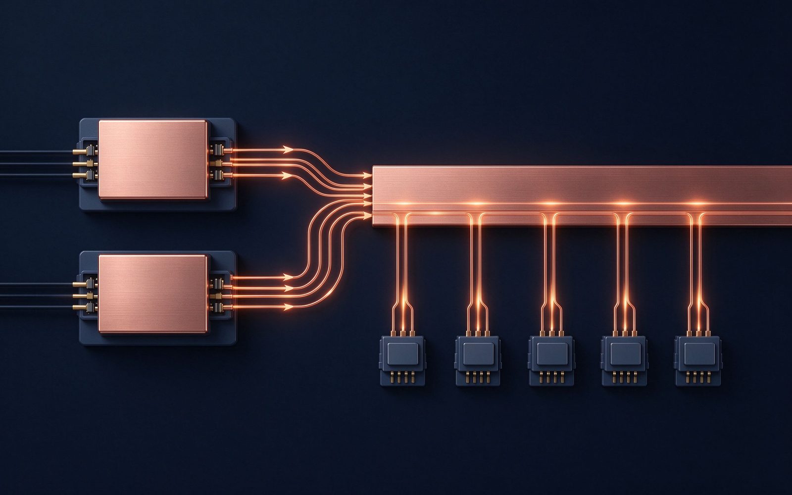
The design point to internalize is full power available anywhere along the rail: taps are not fixed at the ends, loads can draw current at arbitrary positions, and the same bar accepts redundant supplies feeding in from one side while modules draw from everywhere. The rail can also bolt to a conventional busbar, combining both connection styles, or end in a blade assembly that mates dual-bolt cable lugs directly. Environmentally, reference rails run from +10 to +90 °C in operation, withstood vibration and shock regimes and thermal shock to −55 to +125 °C, which is what you expect from a cabinet-mounted trunk. When you size the feeder side, run the conductor numbers against our busbar ampacity chart; the rail itself is sold by its tap density and modular length, not by a single ampacity table.
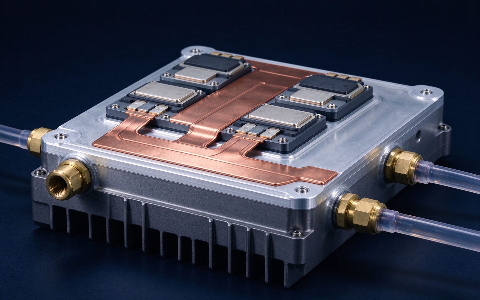
If the rail handles distribution outside the module, the laminated busbar handles distribution inside the unit. A reference design is telling: a multi-layer laminated bar built as a monolithic primary distribution inside a power distribution unit, carrying 5 circuits rated 400 A in total, with a 100 A output at every single position, mated to the drawer through a custom blind-mate interface. The drawer side carried up to 500 A of total throughput through that interface.
What that replaces is a wire harness with hundreds of individual terminations. Every termination in a harness is a contact resistance, a thermal spot and a loosening risk waiting for vibration; the laminated bar collapses all of them into one insulated part whose internal resistance is essentially the copper itself. Stacked planes also bring the electrical benefits this geometry is known for: low inductance, minimal voltage drop, and a controlled partial-discharge level, plus the option of interleaved ground planes between power layers, which raises inter-layer capacitance and suppresses rectifier switching noise coupling into sensitive backplanes.
The geometry follows the envelope, not the rectangle. The same construction family has been formed into a pentagonal, five-sided shape rotating about its center, feeding circuit boards at each edge from a central input, for a compact power-distribution function where a rectangular bar would not fit, with flexible cables entering through a center hole. That freedom is why our power-electronics laminated busbars are quoted as shaped stacks: 1–6+ conductor layers, C11000 copper with aluminum on request, PET, Nomex or epoxy dielectrics, up to roughly 1000 A, with the terminal interface co-designed to your drawer or module connector rather than retrofitted after layout.
The clearest live reference for the whole architecture is a 48 VDC redundant cabinet. A 150 cm, 200 A rail mounted vertically on the cabinet wall, fed by three 48 VDC supplies in (n+1) configuration through 8 AWG flexible cable, with squeeze-to-release tab cable assemblies carrying power out to option modules. Up to 90 plug-in modules can tap the rail at any point along its length.
Each choice has a reason. Vertical mounting turns the cabinet wall into the distribution plane, so every module slot reaches the rail without overhead cable runs. Three 8 AWG feeds share the input current, and because the arrangement is n+1, any one supply can be lost and the rail stays energized. Squeeze-to-release tabs mean a module swap in seconds, with no tools and no torque checklist.
A second reference case shows the supply-side detail. Two parallel redundant supplies, each able to carry the full 150 A load on its own, feed a laminated bar around a tight cabinet-door bend through two runs of 2 AWG cable, each supply on its own cable, landing in a fused cable lug with captive stud hardware. The captive stud matters: it removes loose hardware from the assembly line, and the flexible routing around a sharp corner is exactly where a rigid bar cannot go.
What the rail replaced is worth stating, because it is the commercial argument for the whole approach: hard-wired sheet-metal distribution, where each option module was a wiring project, slow to change and prone to the classic sheet-metal connection failures. The plug-in version cuts module-change labor sharply and improves mean time between failures. The same redundancy-and-hot-swap pattern recurs wherever uptime is the value proposition, from telecom shelves to energy storage system distribution racks, where n+1 feeds and de-rated joints are the baseline expectation.

Redundancy and hot-swap are not connector features; they are architecture decisions you make before the parts are chosen. The principles we apply on every distribution review are:
The payoff is operational, not electrical: a shelf grows from a few option modules to dozens by plugging them, and a failed supply swaps while the rest keep running. The same discipline shows up on the fast-charge side, where parallel front-end power modules in EV charging stations are paralleled, de-rated and hot-swappable on the same n+1 logic. If your architecture mixes rails outside and laminates inside, put the interface between them on the DFM list early: that joint is where the two derating worlds meet.
A telecom fuse panel needed its branch rating raised from 15 A to 20 A per position to stay competitive. The catch: the existing discrete-wire layout would overheat and damage neighboring components at 20 A, inside the same panel volume. The tempting response, thicker wire everywhere, was not available; the volume was fixed.
The fix was a busbar built from discrete single conductors with laminated polyester insulation, sized to fit the existing footprint, delivered as a complete subassembly: busbars plus fuse holders, mounting brackets, circuit boards and terminal blocks. Raising the rating was not about adding copper; it was about replacing bundled wire and loose joints with a single insulated conductor path that sheds heat through a controlled laminated surface. The overheating had come from the wire bundle and its dozens of joints, not from a lack of copper capacity.
The transferable lesson is the useful part of the case. Whenever the brief is more current through the same space, the first question is not conductor thickness but whether discrete wiring should be replaced by a laminated discrete-conductor bar. The laminated polyester insulation does double duty: it isolates adjacent conductors tightly, and the finished, flat surface radiates far better than a bundle of wires could. Delivering the fused subassembly, rather than bare bars, also cut the panel builder's own assembly cycle time, which is the recurring commercial argument for integrated distribution over loose parts.
The pattern generalizes. Legacy enclosures keep getting next-generation power electronics squeezed inside them, and the constant complaint is thermal: the new runs hotter than the old. Nine times out of ten, the heat is not in the new semiconductors alone; it is in the old distribution wiring the semiconductors feed. Replacing that wiring with a shaped, insulated bar recovers the margin the enclosure never had.
Q: What distribution voltages do modular power-distribution rails target? A: Reference designs center on 48 VDC rack and shelf distribution, insulated to 600 VDC operating with a 1500 VDC dielectric to ground. At these levels the binding constraint is voltage drop and heat, not insulation.
Q: How long can a modular rail be? A: Reference rails daisy-chain from 6 inches to 6 ft in 6-inch increments, and the 750 A class version comes in single- or dual-rail at any length up to 6 ft. Longer trunk runs are usually handled by bolting the rail to a conventional busbar.
Q: Can I tap a rail anywhere along its length? A: That is the design point. The louver contact system lets plug-in modules mate at arbitrary positions, which is exactly how one vertical rail supports on the order of 90 option modules without rewiring.
Q: When does a laminated busbar beat hard wiring? A: When circuits multiply — five circuits at 400 A inside one PDU — when low inductance or noise control matters, or when a blind-mate drawer interface is required. For two fixed points and a steady load, a routed single bar or cable remains the honest answer.
Q: How do you keep a redundant rail safe to service? A: Keyed housings for polarity, positive locking at every tap, current-interruption-rated hot-swap interfaces, and independent supplies so any single swap never drops the bus. The interface rating is always checked against the open-circuit voltage, not the nominal bus voltage.
Send the current profile, voltage class and installation conditions — we will size the busbar and document the calculation with your quotation.
Send the current profile, voltage class and installation conditions — we will size the busbar and document the calculation.
