Every custom busbar program starts the same way: an engineer sends a drawing, a procurement team asks for a sample, and both sides hold their breath on lead time. The reality is more predictable than it looks. A simple flat stamped sample can be cut, plated and shipped in as little as three days; a multi-layer laminated assembly with welded terminals and a full test menu realistically runs two to eight weeks. What separates a fast program from a slow one is not the supplier's speed — it is the quality of the data package, the tooling decision made up front, and a test plan agreed before the part is cut. This guide walks the full prototyping process, the verification gates, and the common failure modes that turn quick samples into slow ones.
Every custom busbar program starts the same way: an engineer sends a drawing, a procurement team asks for a sample, and both sides hold their breath on lead time. The reality is more predictable than it looks. A simple flat stamped sample can be cut, plated and shipped in as little as three days; a multi-layer laminated assembly with welded terminals and a full test menu realistically runs two to eight weeks. What separates a fast program from a slow one is not the supplier's speed — it is the quality of the data package, the tooling decision made up front, and a test plan agreed before the part is cut. This guide walks the full prototyping process, the verification gates, and the common failure modes that turn quick samples into slow ones.
Buyers treat samples as engineering's problem, but the sample stage is where procurement risk is actually retired. A sample answers four questions no drawing can: does the part fit the assembly; does the plating survive the environment; does the joint run at the right temperature; does the supplier's process hold the tolerances you specified? Every one of those questions, answered late, becomes a field failure or a requalification. That is why the smart purchasing teams route the sample-to-series path formally: sample, verify, then commit tooling. The same logic applies whether you are prototyping a battery module interconnect or a switchgear busbar — the part is small, but the learning is the product.
Lead time is set before the drawing is sent, by the completeness of the package. The nine items: (1) 2D drawing with dimensions and tolerances; (2) 3D model; (3) currents and voltages, including peak and duty cycle; (4) ambient and target temperatures; (5) dielectric and insulation class, plus PD requirement; (6) plating specification and thickness; (7) terminal types; (8) annual quantity and target lead time; (9) test and documentation requirements. Missing items force the supplier to assume — and assumptions differ. A missing duty cycle produces a cross-section guess; a missing plating spec produces a corrosion risk. Suppliers who quote from complete packages quote faster and closer. The design guide published on this site lists exactly what a manufacturable busbar drawing contains.
A prototype follows the same process as production, with lighter tooling. Copper or aluminum strip is cut — laser for prototypes, stamping where dies exist — formed and bent, layered with dielectric, laminated in a press, terminals welded, and the assembly plated or coated. For a rigid flat part the process is short: cut, plate, inspect, ship. For a multi-layer laminated assembly it lengthens: each dielectric layer and each lamination cycle is a step, and welding terminals adds its own setup. Suppliers with in-house laser cutting, lamination and welding compress the chain because nothing waits on a subcontractor. The factory video tour at SHANYUAN shows the real process — stamping presses, lamination, welding and the quality gates — so a buyer can see which steps a prototype actually runs through.
Published supplier practice brackets the range: expedited prototypes in 2–3 business days for simple parts; prototype samples typically 2–8 weeks for laminated complexity; mass production 3–6 weeks after design approval. Four variables move the number: layer count and lamination steps, terminal welding content, plating complexity (silver and nickel add process days), and test scope (PD testing, thermal cycling and altitude-equivalent tests extend the schedule far beyond a dimensional check). A single-layer flat copper bar with tin plating is the three-day case; an eight-layer assembly with welded terminals, silver plating and a full electrical test menu is the eight-week case. Ask the supplier to break the lead time into process steps, and the number stops being a mystery. The order and shipping guide explains how lead times are quoted at SHANYUAN.
Prototype tooling matters more than people assume. A laser-cut flat bar needs only a cutting program and a plating rack — hours of setup. A laminated part needs lamination fixtures, and a welded assembly needs weld jigs plus the fixture that holds the parts in position during welding; those are the steps that turn days into weeks. The experienced supplier separates the prototype path from the production path: prototype tooling is universal and adjustable, production tooling is dedicated and amortized. When you receive a prototype quotation, ask which steps are tooled and which are manual — the manual steps are where your design can still change cheaply, and the tooled steps are where change starts costing money. The manufacturing process video shows both paths at SHANYUAN, so the buyer can see which steps the quote actually covers.
The whole point of a prototype is to delay the tooling commitment. Prototype parts are cut with laser and formed on universal tooling; production parts use dedicated stamping dies, lamination fixtures and welding jigs. That is why prototype cost is higher per part and production cost falls — the tooling amortizes. The procurement discipline: agree the tooling boundary before the sample ships. If the design will change, keep it on laser and universal tooling; if the sample validates a frozen design, commit the die and the fixture in the same cycle. Suppliers who are honest about the tooling boundary — like the custom busbar quoting process — let buyers stage the spend correctly.
A worked example makes the lead time tangible. A single-layer laser-cut copper bar, 200A, tin-plated, no welding: cutting program, deburr, plate, inspect — two to three business days, and it ships with dimensional and continuity records. Add a dielectric layer and lamination: five to eight business days. Add welded M6 terminals: ten to fifteen days. Add silver plating and a 1,500V withstand test with PD: three to four weeks. Add thermal cycling over a wide range: five to six weeks. Every feature is additive, and the supplier should quote it as a step list. When a buyer sees a nine-week prototype quote, the question is not why it is slow — it is which of the added steps the program actually needs, and whether a simpler sample can retire the risk earlier. The custom quotation process lists the steps so the buyer can trim scope consciously.
There is no commodity MOQ for a custom laminated busbar — each project is engineered to a footprint, and a single prototype piece is a legitimate order. Typical patterns: 1–10 prototype pieces at 5–10 days; pilot runs of tens; serial production from hundreds. What matters is not the number but the purpose: one piece validates fit and form; five pieces validate process repeatability; ten plus validate welding and plating consistency across a mini-run. For an engineering team, the pilot run is where dimensional and electrical test gates get their real exercise, which is why we recommend staging: single sample for fit, then a short pilot for process. The procurement staging guidance covers the quantities at each stage.
Staging also spreads the engineering load: the first sample answers the geometry questions while the pilot answers the process questions, and the serial phase runs on a frozen baseline. Procurement teams that treat the whole path as one step often end up paying prototype prices at serial quantities or serial tooling costs on an unvalidated design. The staged path is slightly slower in weeks but dramatically safer in cost — discovering a welding inconsistency at ten pieces costs days; discovering it at a thousand pieces costs a program.
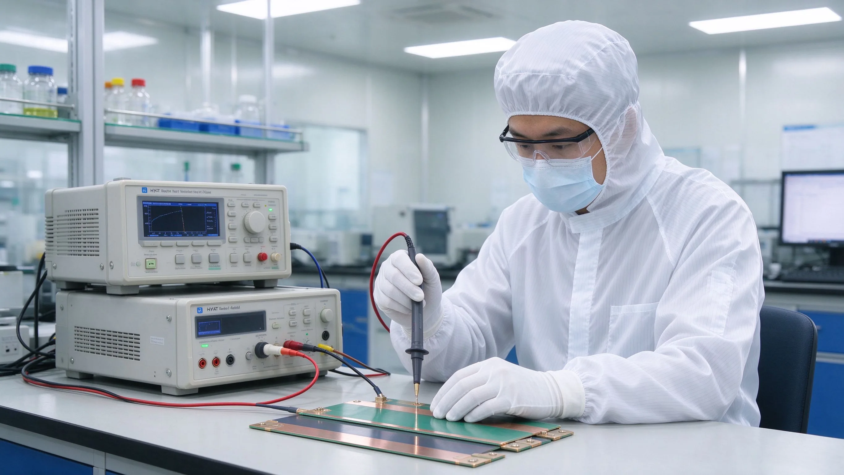
Every sample should ship with evidence, not just the part. The baseline menu: dimensional inspection against the drawing (CMM or fixture); continuity; insulation resistance; and dielectric withstand at the specified voltage. Add application-specific tests: temperature rise at the duty current for high-current parts; thermal cycling and vibration for moving systems; partial discharge for high-voltage laminated assemblies; torque testing where bolted joints carry the current. The quality evidence page lists the standard test set and the reports that ship per order. If a supplier sends a sample without test data, the sample has only proven the shape — not the design.
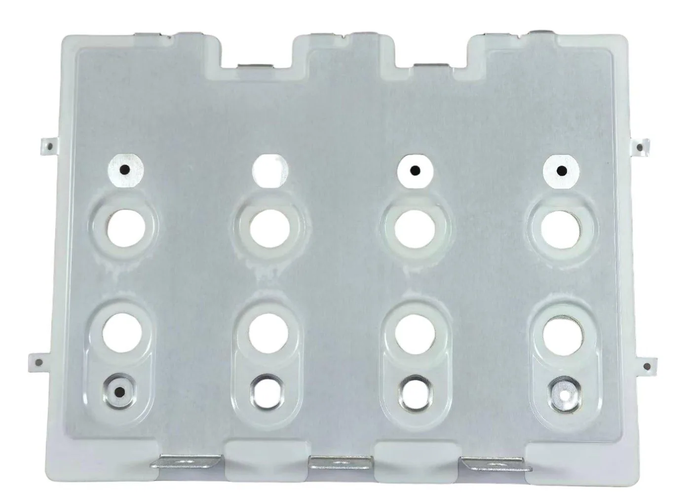
The staging logic has a direct effect on cost. A single sample proves geometry; a five-piece pilot proves process repeatability and lets the supplier measure dimensional drift across a mini-run; a ten-piece run adds statistical meaning to the electrical test results. Procurement teams that jump from one sample straight to production tooling take on the risk that the process — welding consistency, plating thickness uniformity, lamination pressure across the stack — has never been demonstrated at serial tolerance. The staged path is slightly slower in weeks but dramatically safer in cost: discovering a welding inconsistency at ten pieces costs days; discovering it at a thousand pieces costs a program. The pilot run is where the quality gates that protect serial production get their first real exercise.
Most prototype delays are not manufacturing problems — they are specification problems discovered late. The five classics: (1) the duty cycle was missing, so the cross-section is wrong and the part runs hot; (2) the plating spec was missing, so the joint corrodes or the contact resistance fails after cycling; (3) the dielectric class was underspecified and the withstand test fails; (4) tolerances were over-specified — a ±0.05 mm callout on a stamped feature doubles the cost and the schedule; (5) the assembly environment was not described, so the part does not fit the fixture or the terminal spacing. Every one of these is cheaper to fix at the data stage than the sample stage. A good supplier flags them in the DFM review before cutting metal — the design-for-manufacture checklist is written around exactly these traps.
Partial discharge deserves its own paragraph because it is the most misunderstood prototype test. PD testing at the system voltage — 1,500V DC systems typically test at a multiple of the working voltage with an AC excitation — reveals voids, delamination and dielectric defects that a simple withstand test misses, because withstand only proves the part did not break down and PD proves there is no ongoing discharge. A sample that passes withstand but fails PD is a part that will degrade in service, not a part that is fine. For high-voltage laminated busbars, PD is part of the qualification, and the test record should state the test voltage, the measured discharge magnitude in pC, and the background noise level. The PD engineering notes explain the physics; the sample test plan should include it where the voltage class demands.
Rarely is one sample the final answer. The iteration plan should be explicit: round one proves fit, form and electrical baseline; round two closes the deltas — revised dimension, different plating, adjusted torque spec — and re-verifies the changed tests only, not the whole menu. Fast iteration depends on two things: the supplier kept the design on universal tooling (so changes cost days, not die revisions), and the test records from round one are complete enough to compare. Re-running the full test menu on every round wastes the exact lead time prototyping is meant to save. The discipline of incremental verification is what the quality gates in the plant formalize for serial production, and it applies from the first sample.
The drawing errors that trigger DFM findings are predictable, and knowing them makes your package faster: dimensioning from the edge instead of from a datum; tolerances tighter than the process capability (stamping holds roughly ±0.1mm, laser cutting ±0.2mm, and calling ±0.05mm on a formed feature buys inspection cost, not quality); bending radii smaller than the material thickness; plating specified on edges that the rack cannot reach; and dielectric requirements stated as "insulated" without a class, voltage or thickness. A good DFM review catches these before the sample, saving the two-week round trip that a drawing-only purchase incurs. The design-for-manufacture checklist on this site is written around exactly these findings and is a useful pre-flight check before the package goes out.
The sample-to-production handover is where cost is won or lost. At handover, freeze four things: the approved drawing (with the DFM changes incorporated), the test plan and its pass criteria, the tooling boundary, and the process qualification evidence. Production then runs against that frozen baseline — any change after handover is a change order with its own schedule. Suppliers with production lines run sample and serial on the same equipment, which means the handover is documentation, not requalification. The quote process page explains how the one-business-day technical response works and what a production quotation contains, so the transition from prototype to serial pricing is a known step, not a surprise.
Fast iteration also depends on honest change control. Every delta should be written down: what changed, why, and which test evidence is affected. A plating change invalidates corrosion and contact-resistance evidence but not dimensional data; a dielectric change invalidates the withstand and PD records but not the continuity results. Suppliers who track this mapping let you re-verify only the affected tests, which is the difference between a two-week iteration and a six-week one. The same discipline applies at the drawing level: revision letters on the drawing, a change log, and a clear statement of which revision the test records apply to. This is standard practice in automotive and aerospace qualification, and it is exactly what makes the sample-to-series transition predictable rather than heroic.
Prototype spend follows a simple rule: spend on verification, not on tooling. Keep the part on laser cutting and universal tooling until the design is frozen; invest in the test menu that retires risk — temperature rise, withstand, cycling — before the die; and stage quantities so the pilot run pays for process learning rather than inventory. Plating is the biggest per-part variable on prototypes: tin is the cheap default, silver and nickel add days and money, so specify plating by function, not habit. A supplier who quotes the prototype and the production part from the same data package, with the tooling line item separate, makes this staging easy — that is the model behind the engineering inquiry at SHANYUAN.
The handover documentation matters more than the part itself at serial launch: the approved drawing becomes the master, the test plan becomes the inspection standard, and the process qualification records become the baseline for every subsequent lot. A supplier with in-house laser cutting, lamination and welding can attach the same operators and machines to serial production, which makes the sample-to-serial delta purely a matter of tooling and quantity rather than a change of factory. Buyers should ask at the handover who will build serial parts, on which machines, with which test stations — the answers predict the consistency better than any certificate. The factory tour and the quality evidence pages document the actual lines and gates at SHANYUAN so the handover conversation is grounded in what the buyer can verify.
What is the fastest possible sample lead time? For a simple flat stamped or laser-cut bar with tin plating, 2–3 business days is realistic; complex laminated assemblies run 2–8 weeks. The data package and test scope set the number. Is a one-piece sample order legitimate? Yes — custom laminated busbars have no commodity MOQ, and a single prototype validates fit and form. Pilot runs of tens validate process. What tests should a sample ship with? Dimensional inspection, continuity, insulation resistance and dielectric withstand as the baseline; temperature rise, cycling, vibration or partial discharge per application. When should I commit production tooling? Only after the sample validates the design and the DFM review is closed — tooling commits money, and prototyping exists to defer it.
Every hour spent on DFM before a custom busbar quote saves a week of rework. This is the c
Read article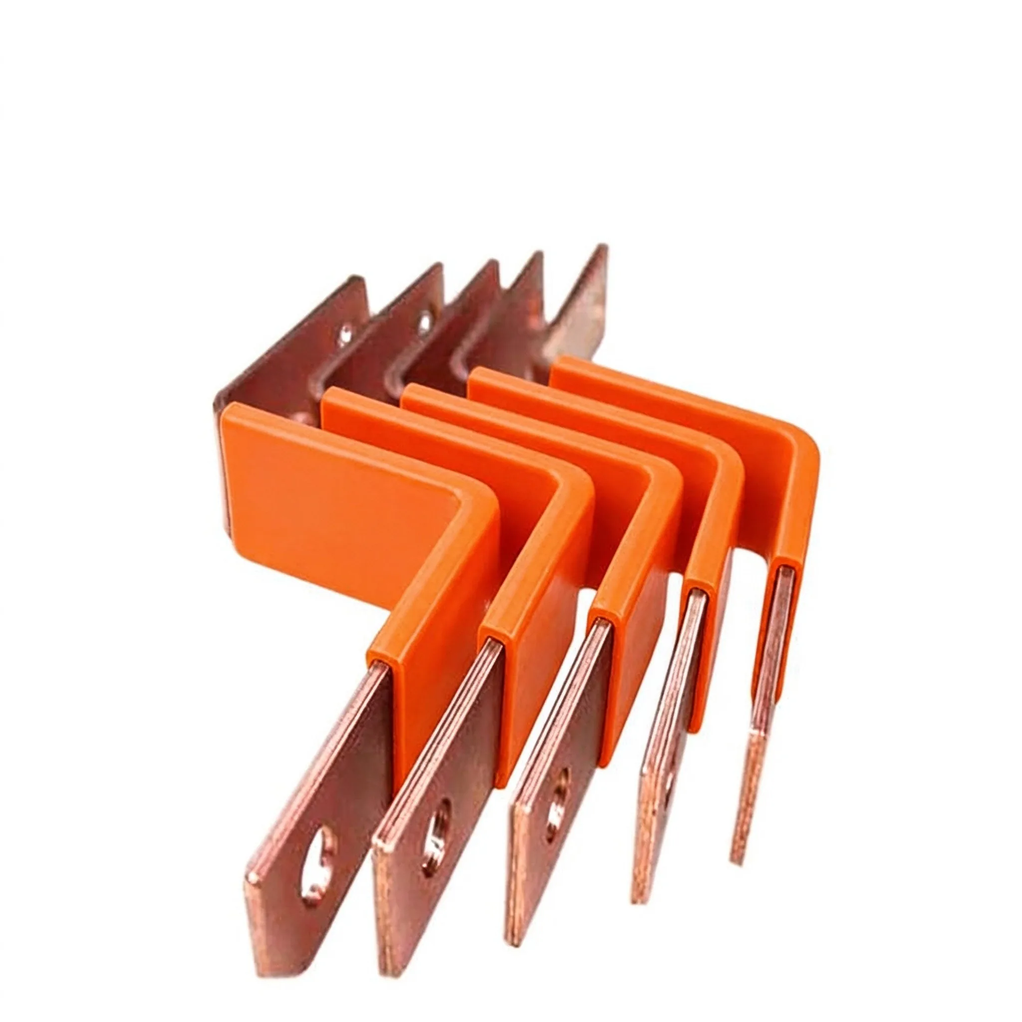
Buying a laminated busbar is not like buying a standard connector. The part is custom, the
Read article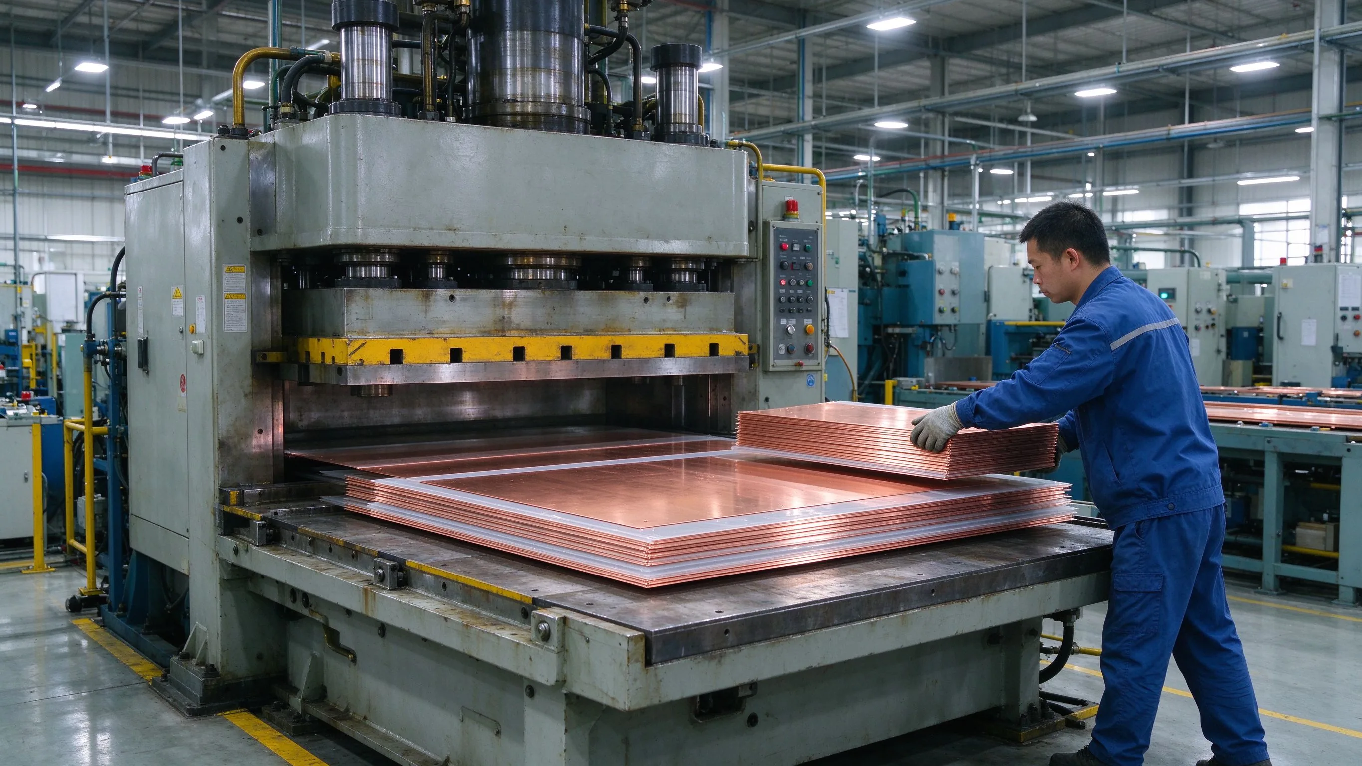
From C11000 copper coil to a fully sealed, tested multi-layer busbar, this walkthrough exp
Read article
Thomas O'Brien is a manufacturing process engineer with 14 years in stamping, lamination and terminal machining for laminated busbars. He manages production lines for precision-cut profiles, insulation layering and CNC terminal processing, and focuses on dimensional control and repeatability at
Send the current profile, voltage class and terminal types — our engineers reply within one business day.