Partial discharge is the slow, invisible enemy of high-voltage insulation. This guide explains what it is, where it starts in a laminated busbar, the 10 pC acceptance level, and the design rules that keep it out of production.
Partial discharge (PD) is defined in IEC 60270, clause 3.1, as a localized electrical discharge that only partially bridges the insulation between conductors. In practice it appears as short pulses, typically shorter than one microsecond, caused by local electrical stress concentrations inside the insulation or on its surface.
On its own, an intermittent discharge does not immediately damage anything. The problem is cumulative: continuous partial discharge above about 10 pC erodes the insulation over time, and the end point is a gradual loss of dielectric strength that can turn into a short circuit in service. That is why PD is treated as a design target and a production test, not as an optional measurement.
Three things make PD hard to catch. It is invisible: the discharges themselves last under a microsecond, so you cannot see, hear or feel them on a powered-up part. It is slow: months or years pass between the first micro-discharge and any measurable degradation. And it is cumulative: each partial event etches a little more carbonized channel into the insulation until a tracking path bridges the layers. The only practical response is measurement during production testing, plus a stack design that never gives the discharge a starting pocket.
The definition matters operationally. Because a PD pulse partially bridges the insulation rather than fully breaking it, a hipot or withstand test does not detect it: a part can pass a 2.5 kV withstand test cleanly and still discharge at 1.2 kV under the probe. PD measurement is a separate instrument, tuned to the pulse band defined in IEC 60270, and the output is a charge level measured in picocoulombs (pC), not a pass/fail voltage. For power-electronics engineers, the practical question is not whether a busbar can discharge, but where in the stack a discharge would start. If you are new to laminated construction overall, start with our laminated busbar design guide.
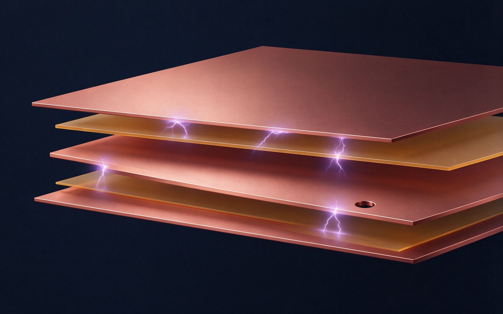
Flexible film and rigid board insulation are very sensitive to gaps at their interfaces, either between two insulation layers or between the insulation and the conductor. Those gaps fill with air. Air is the weakest link in the dielectric system, and its dielectric strength depends on pressure, which depends on altitude. Every trapped bubble is a candidate discharge site.
Where exactly do the pockets live? Typically at three places: between two dielectric films where the lamination pressure did not fully wet the glue layer; at the interface between film and conductor cut edge, where the film must wrap around a punched profile; and around through-holes and terminal windows, where the geometry forces the film to bend and stretch. Production control targets all three: clean material prep, controlled lamination temperature and pressure, and edge sealing that closes the cut dielectric edges.
The voltage class sets how seriously you take this, and the automotive-versus-industrial split decides whether you need a rigid inter-layer board at all:
| Aspect | Industrial / traction | Automotive |
|---|---|---|
| Voltage range | 1000–6000 V | 400–800 V |
| Partial discharge | Critical; rigid inter-layer insulation mandatory | Not required below 800 V; film alone typical |
| Lifetime target | Up to 25 years | Under 5 years |
| Typical test voltage | Per PD and clearance design | 2.5 kV AC / 3.7 kV DC |
Production-side control matters as much as geometry. Clean conductor prep before layup, controlled glue activation under pressure, and a lamination recipe that holds dielectric thickness within tolerance are what turn a good drawing into parts that all pass. A stack designed for zero air gaps still has to be built with zero air gaps; that is why our DFM review flags the geometries where bubble trapping is most likely, before tooling. That split drives a lot of product decisions: our power-electronics laminated busbars for high-voltage converters use rigid inter-layer insulation plus sealed flexible film, while lower-voltage parts rely on film alone. Whichever class you design in, the rule is the same: eliminate air gaps, because every gap left in the stack is a place where PD can start.
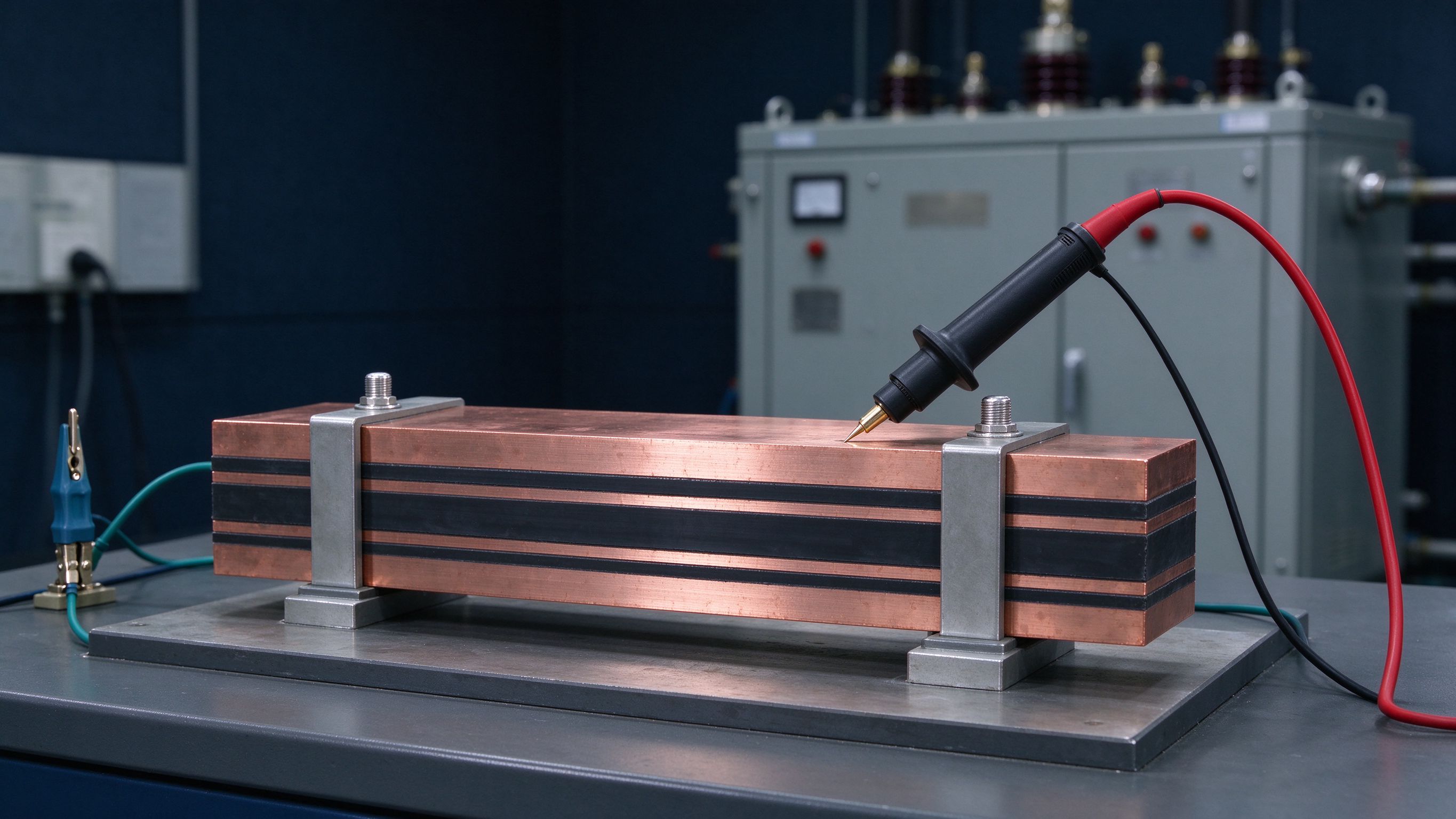
Engineering practice for laminated busbars is straightforward: verify partial discharge on every finished part and keep it below 10 pC, even at test voltages higher than the nominal operating voltage. For low-voltage automotive busbars, the maximum test voltage is typically 2.5 kV AC or 3.7 kV DC, measured well above anything the part will ever see in the vehicle, so a clean result gives you margin over the whole life cycle.
What does a production PD test actually look like? The busbar sits on a bench, the test voltage is raised smoothly to the agreed level, and the measurement circuit reads the apparent charge of every discharge pulse. A clean result is not a single number once; it is a stable reading below the acceptance threshold held for the full test duration, with no growing pulse trains that would indicate incipient tracking. We also run the check at voltages above nominal, because a margin that looks comfortable at operating voltage vanishes fast as the insulation ages.
Why the 10 pC number? Intermittent discharge below the threshold is essentially harmless over service life; continuous discharge above it accelerates erosion at a measurable rate. The 10 pC level is the boundary the industry converged on between benign and damaging, and testing well above operating voltage is how you prove margin against the defects a part accumulates over decades: micro-voids from lamination wear, seals aging in humidity, and creepage paths forming on the surface.
On our production line, every lot passes in-house QC: hipot, insulation resistance, dimensional checks, visual inspection and continuity, with partial discharge verified as part of the high-voltage check. Batch test records are kept, and certificates of conformance plus PPAP-style documentation are available on request. You can read more about that process on our quality page.
The busbar has to be designed against the critical electrical field, which is voltage divided by distance. The rule of thumb we work from is roughly 1 mm of rigid insulation per kV between conductor sub-assemblies, with typical rigid-insulator thicknesses from 1 mm to 6 mm, commonly a glass-reinforced polyester board.
Worked example: a 3000 V DC traction supply has a maximum operating voltage around 4800 V, which points to a 5 mm rigid insulator between conductors. The higher the maximum operating voltage, the thicker the rigid insulation between layers.
Two material details quietly dominate the result. First, CTI: the comparative tracking index of the film decides how much creepage you need between free terminals. With a good-CTI material such as standard PET versus a poor-CTI material such as polyimide, the required creepage distance typically doubles, and CTI becomes a critical parameter beyond 1000 V. Polyimide, despite its high temperature rating, is overall suitable only below about 600 V for this reason. Second, edge sealing: a seal that opens at altitude or humidity is an instant air pocket.
Dielectric choice (PET, Nomex or epoxy films) also sets the thermal class of the assembly; see our guide to dielectric selection for laminated busbars. Note the tension with low inductance busbar design: thinner inter-layer insulation improves inductance but worsens the PD margin. Every high-voltage busbar we release is a negotiated balance between the two.

Air pockets are bad enough at sea level; they get worse with altitude. The breakdown voltage of a gas follows Paschen's law, meaning it is a function of the product of pressure and electrode gap, p·d. For air, breakdown strength is about 3.1 kV/mm at sea-level pressure, falling to roughly 2.0 kV/mm at 0.5 bar, about 5500 m altitude, and lower still higher up.
Two consequences follow. First, if a transient voltage on the equipment exceeds the air breakdown voltage at the operating altitude, a flashover occurs unless creepage and clearance distances are respected. This has to be compensated in the design phase, not at installation. Second, prototypes and production parts must be electrically tested with a corrected test voltage that accounts for altitude, or the test gives you false confidence.
The design response has three parts. Respect creepage and clearance distances sized for the lowest pressure you will ever see, not the showroom altitude. Test prototypes and production parts at a corrected test voltage that accounts for reduced dielectric strength, so your type test agrees with reality on the mountain. And derate the current, because thin air cools worse as well as insulates worse; components are typically derated above 2000 m on both counts. If your equipment lives on a mountain-top solar farm or in traction converters with unpressurized mounting locations, tell us the altitude in the quotation request. For grid-tied converters pushing toward 1600 VDC, see our solar and wind inverter busbar page.
A PD-controlled busbar is designed against the worst case, not the nominal voltage. Send us the following and we will size the insulation, seal design and test plan with you before any tooling is cut:
One more practical note: if your system runs above about 1000 V, treat the PD design as a joint exercise early. Changing creepage distances or adding a rigid insulator after the mechanical layout is frozen means re-cutting tooling; raising it at DFM stage costs nothing. The resulting defense has three layers and they stack: design the critical field down with rigid insulation thickness; choose materials, a good-CTI film and sealed edges, that deny the discharge a starting pocket; and prove on every lot that the measured PD stays below the limit. Skip any layer and the others carry all the risk alone.
Temperature ties directly into this: stressed insulation ages faster when it runs hot, and our busbar thermal management guide covers the lifetime math, including the ampacity derating for altitude and enclosure. That covers the full arc: mechanism, criterion, test, design, altitude, and the inputs we need. If anything above raises a question about your stack, raise it at DFM rather than after first article. When you are ready, send the drawing to us through contact engineering for DFM review; we respond within one business day.
Send the current profile, voltage class and installation conditions — we will size the busbar and document the calculation with your quotation.
Send the current profile, voltage class and installation conditions — we will size the busbar and document the calculation.
