In March 2026, BYD put megawatt charging on the mainstream road: single-gun peak power of 1.5 MW, dual-gun parallel output around 2.1 MW, a 1000 V bus running at up to 1500 A, and a target of 15,000 flash-charging stations by the end of the year (EET-China, March 2026). A week later, module vendors were shipping 80 kW SiC power stages for the same class of hardware - Kehua's new 80 kW VPFC module, for instance, hits 97.5% peak efficiency and targets megawatt-scale sites (PR Newswire, August 2026). The charging pile that sits at the side of that highway has quietly become a high-current power-electronics cabinet, and the DC busbar inside it is doing work that 350 kW chargers never asked for.
In March 2026, BYD put megawatt charging on the mainstream road: single-gun peak power of 1.5 MW, dual-gun parallel output around 2.1 MW, a 1000 V bus running at up to 1500 A, and a target of 15,000 flash-charging stations by the end of the year (EET-China, March 2026). A week later, module vendors were shipping 80 kW SiC power stages for the same class of hardware - Kehua's new 80 kW VPFC module, for instance, hits 97.5% peak efficiency and targets megawatt-scale sites (PR Newswire, August 2026). The charging pile that sits at the side of that highway has quietly become a high-current power-electronics cabinet, and the DC busbar inside it is doing work that 350 kW chargers never asked for.
The arithmetic is simple: at 1.5 MW, an 800 V bus needs about 1,875 A, while a 1000 V bus needs 1,500 A. That 20% current reduction directly shrinks busbar cross-sections, cable gauges and connector losses - and in a liquid-cooled gun, every ampere counts twice, once in I²R heating and once in the coolant load that has to carry it away.
BYD's own material explains the escalation differently: the 800 V platform paired with 1200 V SiC devices was the standard of the past few years, and pushing the vehicle bus to 1000 V forced the device rating up to 1500 V - the first mass-produced 1500 V automotive SiC module arrived in the Han L and Tang L (EET-China, March 2026). Charging infrastructure follows the same curve: a pile that must talk to a 1000 V vehicle bus ends up with a 1000 V DC bus of its own.
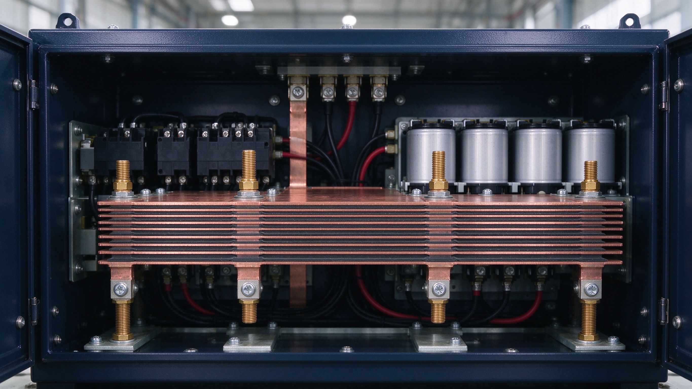
Inside the cabinet, a megawatt charger is a straightforward power chain: AC input → rectifier → DC bus → power modules → output contactor → the gun. The DC bus is where the high-current reality lives. At 1,500 A continuous, the busbar has to be sized for both steady-state temperature rise and the short-time peaks during a charge cycle, and the connection from bus to each 80 kW SiC module is a bolted joint rated for the module's full output.
Most megawatt-pile builders now specify laminated DC-link busbars for the module stack - the same low-inductance construction used in traction inverters - because SiC modules switch at higher di/dt than the IGBTs they replace, and the commutation loop around each module needs to stay tight.
Air cooling stops working somewhere north of 400 kW per cabinet. The 800 kW-class stations on the market run dual-loop liquid cooling: one loop through the power modules and high-current busbars, a second through the charging cable and connector pins (MIDA Power, August 2026).
For the busbar, liquid cooling is a gift and a constraint. The good news: coolant removes heat that natural convection never could, so a water-cooled busbar can run at current densities that would melt an air-cooled one. The constraint: the busbar has to survive inside a sealed, coolant-wetted environment, which means insulation systems rated for the humidity and condensation that come with it. The dielectric stack on a liquid-cooled DC-link busbar needs to hold its dielectric strength wet, and the plating has to resist the coolant chemistry over years of service.
At 1,500 A, the weakest point is never the copper bar - it is the interface. Bolted joints, plug-in contacts and the gun connector all carry the same current through a fraction of the cross-section, and contact resistance dominates the temperature budget. Silver-plated pins with integrated thermal sensors now monitor the contact interface every 10 ms in high-end guns (MIDA Power, August 2026).
On the busbar side, the equivalent discipline is joint design: plating thickness (tin 5-15 µm or silver 2-8 µm at the joint areas), preload control, and spring-washer retention where the pile sits outdoors and vibrates. Our bolted-joint design guidance for vibration applies almost word-for-word to a highway charging cabinet.
The module market is where the 2026 shift is easiest to see. Kehua's 80 kW VPFC module runs SiC devices, holds 97.5% peak efficiency, supports 0 W standby and keeps full power at 55 °C ambient - numbers that only make sense in liquid-cooled megawatt systems (PR Newswire, August 2026). The 40 kW module line, meanwhile, stays relevant for ordinary public stations, where 97.5% peak and 97% weighted efficiency set the bar.
For busbar suppliers the module evolution means two product streams: high-current laminates and solid bars for the 80 kW-class stacks, and lower-current but high-volume parts for the 40 kW-class mainstream pile. Both share the same plating, insulation and test requirements.
Megawatt Charging System (MCS) is designed for up to 3.75 MW - 3,000 A at 1,250 V - enough to charge a long-haul electric truck in under 20 minutes (MIDA Power, August 2026). The standard is now landing in heavy-duty corridors, and the 600-800 kW liquid-cooled stations on sale today are explicitly MCS-ready.
At 3,000 A the busbar story stops being about laminates and becomes about parallel bars and busways: several bars per phase, with the derating that parallel configuration carries, and cooling that is no longer optional at any point in the chain. The physics is the same one we publish in our harmonic and ampacity guidance - just scaled up.
A megawatt station with eight guns pulling simultaneously loads the grid beyond what most distribution transformers were built for - 10 MW transient demand against a typical 315-630 kVA feeder transformer (EET-China, March 2026). The practical answer is on-site storage: BYD's flash-charging sites pair a 225 kWh blade cabinet with a 560 kW grid connection to synthesise 1,360 kW of output.
That adds a second busbar story to every station: the battery rack busbars and the PCS DC link. ESS busbar demand and charging demand are now tied at the hip - one more reason the two markets move together.
Busbar sizing for a charging pile follows the same IEC 61439-style thermal logic as any power electronics cabinet, but two duty-cycle details matter. First, charging is intermittent - 15-40 minutes at full current, then idle - so the thermal time constant of the busbar and cabinet decides how much margin you need. Second, the short-time rating is defined by the pile's own protection: a DC-link fault clears through the modules and their fuses, typically inside a few hundred milliseconds.
Practical approach: size for the continuous worst-case (all guns at full output), verify short-time withstand against the protection curve, then confirm temperature rise in the liquid-cooled condition. Our busbar current capacity guide walks through the same calculation with the 30 °C rise basis we use on our own products.
Charging cabinets live outdoors: salt air near coasts, dust on highways, ice and condensation in winter. The busbar plating has to hold contact resistance through that, and the insulation has to keep its dielectric strength wet. Tin plating on bolted joint areas remains the workhorse; silver shows up where the interface current density is highest, at 8-15 times the cost of tin.
Insulation selection follows the same hierarchy as our surface insulation guide: PET film and laminates where the geometry is flat and volume is high, epoxy powder coating where the part is three-dimensional, and heat-shrink where the customer wants field-friendly rework. UL 94 V-0 flame class is the default requirement in every megawatt-pile spec we have seen.
Across charger-maker RFQs this year, the busbar requirements cluster around a repeatable list: 1000 V DC insulation class; continuous rating at the module-stack current with the liquid-cooled temperature-rise basis; short-time withstand matched to the pile protection; tin or silver plating with thickness specified; UL 94 V-0 insulation; dimensional tolerance per drawing; and per-lot test records - hipot, insulation resistance, and continuity.
Two questions come up in every conversation that did not five years ago: What is the DC-link inductance of your laminate? And do you have a temperature-rise report at full load? Suppliers who answer both with data are the ones who stay in the loop.
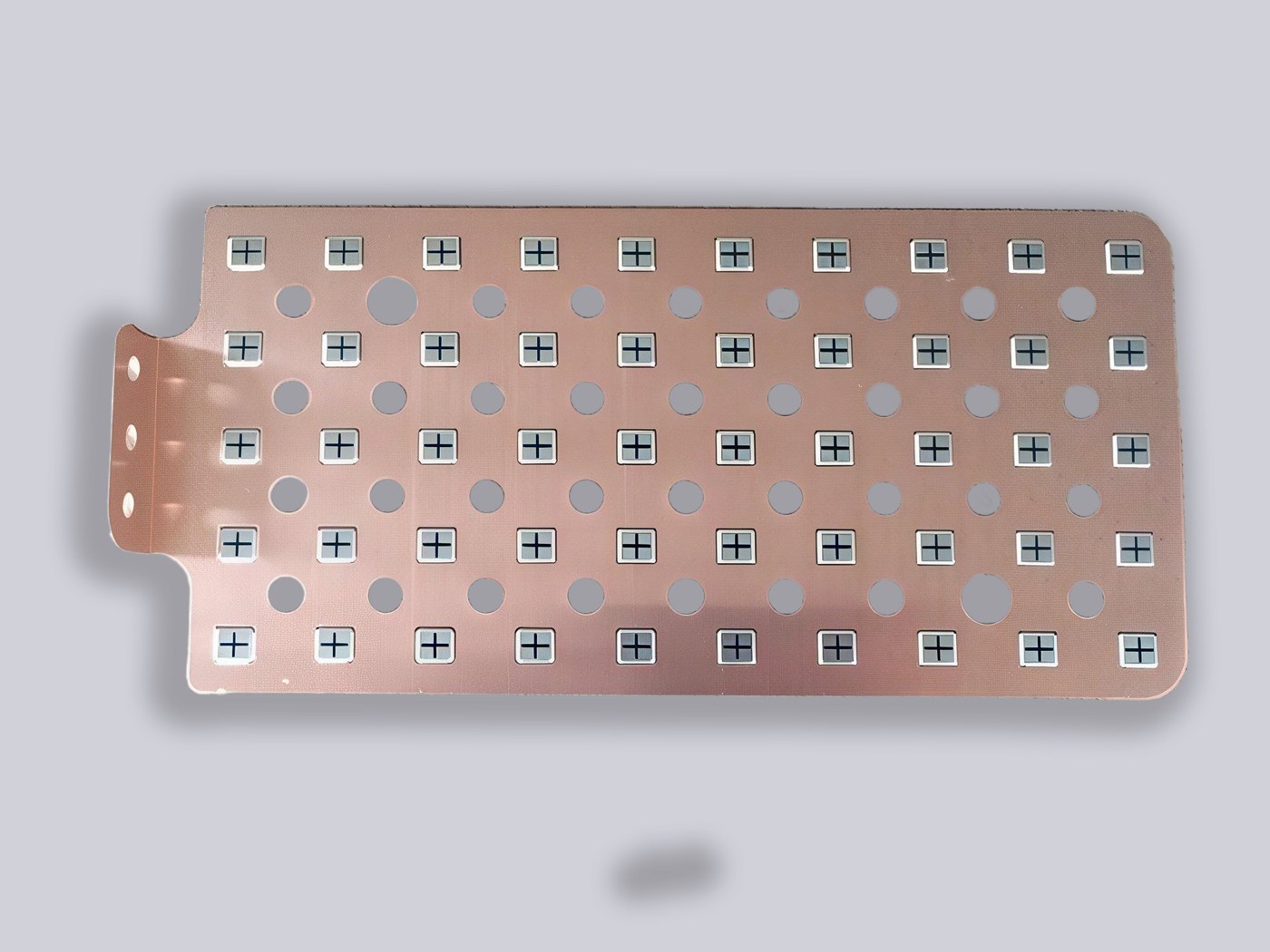
SHANYUAN has supplied busbars for EV charging infrastructure - pile cabinets, battery-pack links and ESS racks - since the 350 kW era. Today our Rizhao plant (17,200 m², 20+ export countries) builds 1000 V-class DC-link laminates for SiC charger modules, multi-layer battery links, and liquid-cooled cabinet bus sections, all on C11000 copper with PET/Nomex/DLF insulation and tin or silver plating.
For a megawatt-pile programme, the starting point is the same as for any power-electronics project: send the current profile, voltage class, cooling arrangement and terminal types. DFM feedback and a quotation follow within one business day.
The liquid-cooled cable solved the handheld end of the megawatt problem: direct-contact coolant flow lets the gun carry 500 A while staying flexible enough for a driver to handle, with surface temperature held below 50 °C (MIDA Power, August 2026). The cabinet end needs the same thinking.
Busbar cooling inside a megawatt pile ranges from cold plates under the laminates to full liquid loops through the module stack. The design rule is simple: decide the cooling path before the busbar geometry is frozen, because a water-cooled busbar can run at current densities that make an air-cooled bar physically impossible, and the insulation system has to be chosen for a sealed, wet environment.
Chargers followed vehicles up the voltage ladder. A 1000 V bus and 1500 A peaks put the pile's own power devices under the same stress the vehicle inverter faces, and the module makers answered with SiC: Kehua's 80 kW VPFC module and BYD's 1500 V SiC devices are different sides of the same escalation (PR Newswire, August 2026; EET-China, March 2026).
For the busbar, higher device voltage means thicker insulation coordination and, at the DC-link laminate, the same low-inductance discipline that protects SiC from switching overshoot. The 2026 pile is electrically a traction inverter with a gun on the end.
Type testing a megawatt-pile busbar follows the power-electronics playbook: temperature rise at continuous rating, hipot and insulation resistance at the 1000 V class, short-time withstand against the pile's protection curve, and thermal cycling for the bolted joints. On the production side, per-lot records - hipot, insulation resistance, continuity, plating thickness - are what the charger OEM's quality audit expects.
Our own test matrix on charging and ESS busbars covers exactly those items, with CoC on request - the same file that lets a pile builder answer a customer's quality questionnaire without re-testing anything.
A megawatt pile concentrates more heat in one cabinet than most plants shed in a whole panel room. The hot spots are never the copper - they are the interfaces: module-to-busbolts, bus-to-contactor, contactor-to-gun. At 1,500 A, a joint that loosens by a few per cent of contact pressure runs visibly hotter, and a hot joint oxidises faster, which makes it hotter still - the classic thermal loop.
The mitigations are all mechanical: plating thickness at the joint (tin 5-15 µm or silver 2-8 µm), preload control rather than torque-only, spring washers where the pile vibrates outdoors, and thermal imaging at commissioning to catch the first-installation joint errors before they compound.
The one-page spec for a charging-pile busbar is short: system voltage (1000 V DC class), continuous current per module stack, short-time withstand against the pile protection, insulation flame class (UL 94 V-0), plating type and thickness, DC-link inductance target if the part is a laminate, ambient and cooling arrangement, and the test documents - hipot, insulation resistance, continuity, temperature-rise report at full load.
That page is enough for three suppliers to quote comparably, and it is the page our DFM review turns around fastest. Send it with the drawing and the current profile; engineering replies within one business day.
Not every megawatt charger runs the same cycle. A fleet depot charges a known fleet overnight and through shift breaks - predictable, block-loaded, easy to size. A highway hub serves whatever pulls in: 1500 A peaks back to back at lunch, idle at 3 a.m. The busbar rating logic differs accordingly: the depot bar is sized for the fleet's worst-case continuous block, the highway bar for the thermal time constant of the pile and the peak-to-idle ratio.
Both end up with the same discipline - document the duty cycle, size the temperature rise on the real profile, verify at commissioning with the thermal camera. The arithmetic is in our current-rating guidance; the duty cycle is yours.
MCS moves from pilot to fleet scale in 2026: 1 MW+ charging at 1250 V and up to 3000 A mak
Read article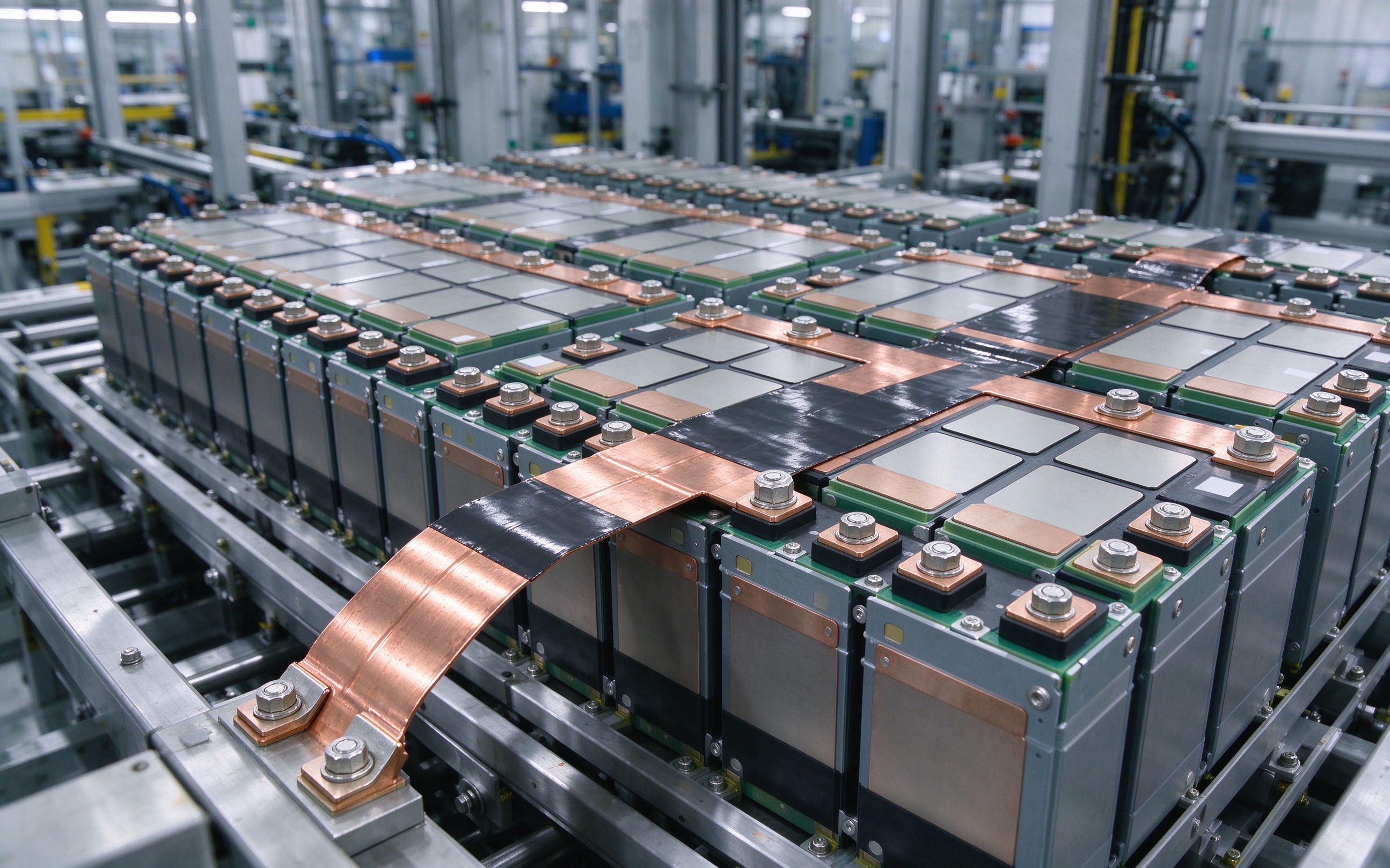
The shift from 400V to 800V vehicle architectures is rewriting the electrical layout insid
Read article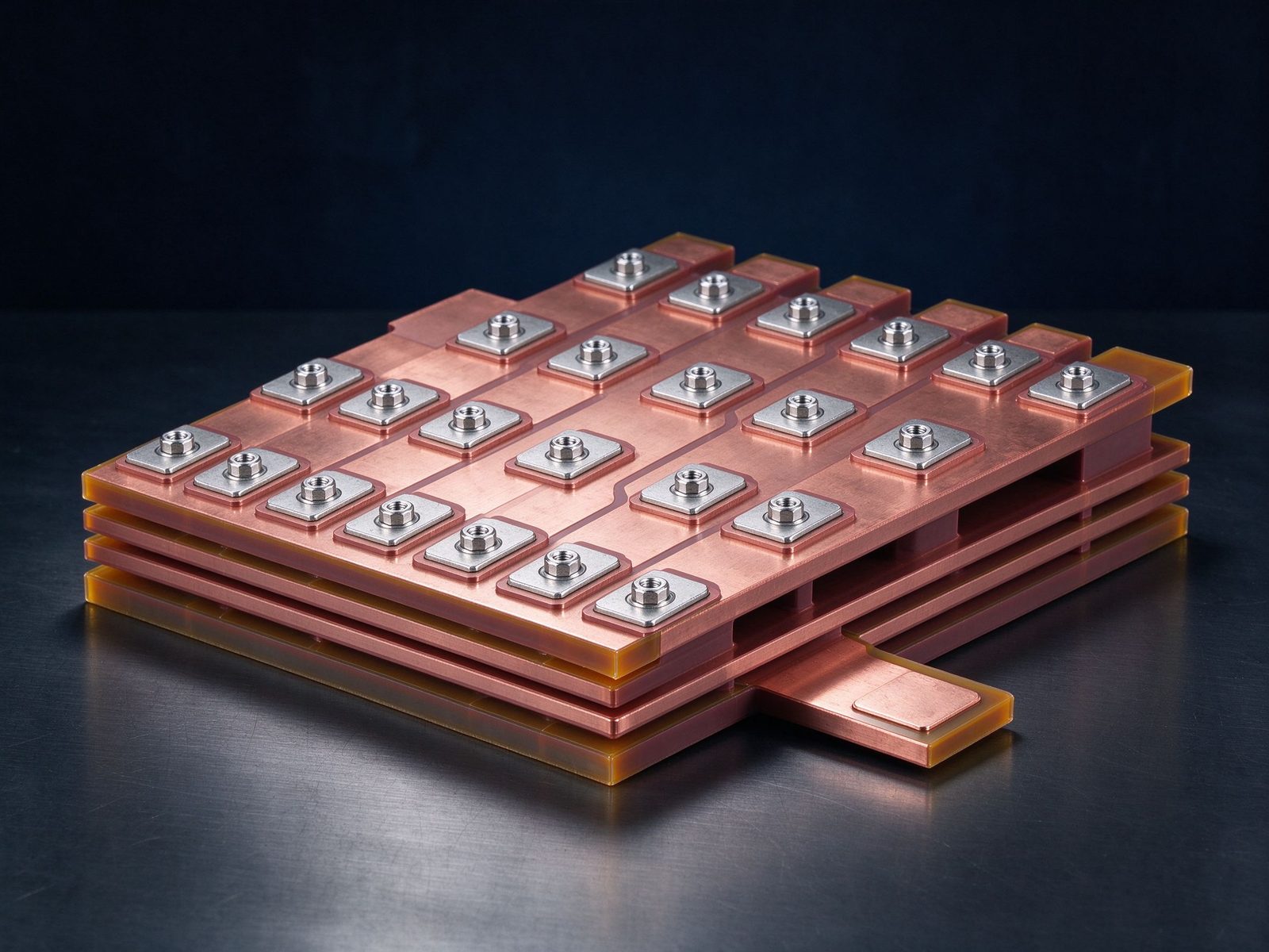
SiC is scaling up — literally. Eight-inch wafer capacity is expanding at double-digit CAGR
Read articleSend the current profile, voltage class and terminal types — our engineers reply within one business day.
