Mon–Fri 9:00–18:00 · CST (UTC+8) · Shandong, China
News · Design

Laminated Busbar DFM Checklist 2026: What to Check Before You Send the Drawing

DFM — design for manufacturing — is the step most engineers skip and most suppliers quietly wish they would not. A drawing that looks correct on screen but ignores tooling, lamination, edge sealing and welding realities comes back with revisions, lost weeks and a quietly inflated price. At SHANYUAN we run a DFM review on every file before we issue a custom busbar quote, and we share that checklist here so you can pre-check your own designs. If you are trying to buy laminated busbars for a new platform, walking this list before you send the PDF is the fastest way to a clean first sample.

By SHANYUAN Engineering Team Design Technical Note

DFM — design for manufacturing — is the step most engineers skip and most suppliers quietly wish they would not. A drawing that looks correct on screen but ignores tooling, lamination, edge sealing and welding realities comes back with revisions, lost weeks and a quietly inflated price. At SHANYUAN we run a DFM review on every file before we issue a <strong>custom busbar quote</strong>, and we share that checklist here so you can pre-check your own designs. If you are trying to <strong>buy laminated busbars</strong> for a new platform, walking this list before you send the PDF is the fastest way to a clean first sample.

1. Layer Count and Stack-Up Definition

The first thing we check is whether the drawing actually says how many layers there are, and what each one does. A laminated busbar is not just a thick plate — it is a defined stack of copper and dielectric layers, usually 1 to 6+ at SHANYUAN.

  • Each layer should have a unique name (e.g. Layer 1 = DC+, Layer 2 = DC−, Layer 3 = phase U).
  • Layer order and orientation must be explicit, including any rotated or mirrored layers.
  • Material and thickness of every copper layer and every dielectric film must be on the drawing (C11000 copper by default; PET/Nomex/DLF dielectric).
  • Any layer that is only mechanical (not current-carrying) should be flagged — we still cut it, but it changes cost.

Missing layer definitions are the #1 cause of quote loops. See the manufacturing process walkthrough for how the stack becomes a part.

2. Edge Margins and Dielectric Overhang

The dielectric film must overhang every exposed copper edge by the design margin. Too little and you lose creepage; too much and the film wrinkles during lamination.
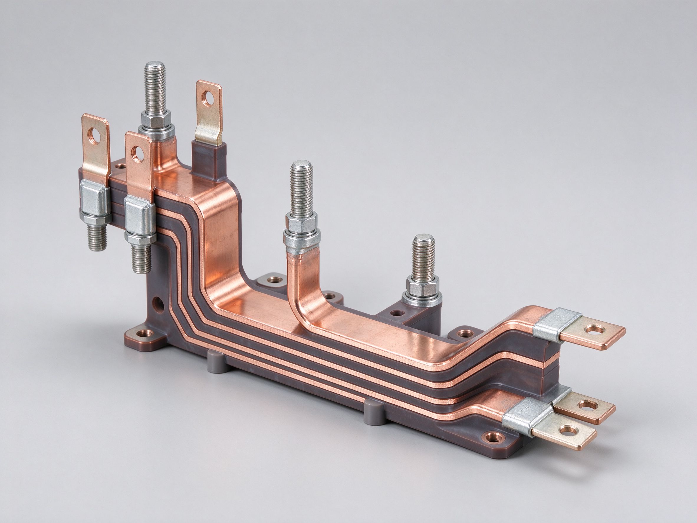
  • Film overhangs copper on every exposed edge — not just the long sides.
  • Margins around terminal cutouts match the drawing's creepage/clearance requirements.
  • Outer edge sealing is specified (SHANYUAN defaults to full edge seal).
  • Any area where copper must remain exposed for welding or bolting is explicitly masked on the drawing.
Why this matters: An exposed copper edge inside a laminated stack is not just a safety issue — it is a place where moisture can wick in. Full edge sealing is standard on every SHANYUAN build; see the dielectric guide for why different films need different margins.
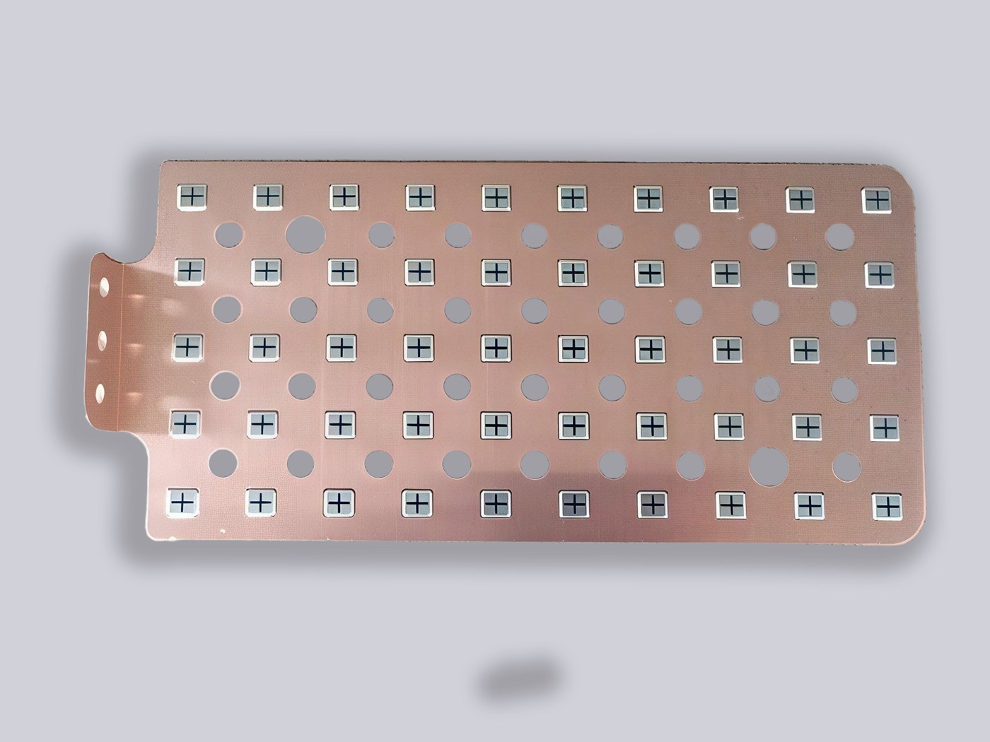
Custom laminated busbar layout with clearly visible dielectric overhang on copper edges
Edge margin check on a custom laminated busbar: dielectric film overhangs the copper on every exposed side before press lamination.

3. Creepage and Clearance Distances

Creepage is the shortest path along an insulating surface between two live parts; clearance is the straight-line air gap. IEC 60664-style tables set minimums based on working voltage and pollution degree. Before you send the drawing, confirm:

  • Creepage between adjacent live layers on exposed edges meets the voltage class.
  • Clearance between live terminals and grounded metalwork meets the same class.
  • Creepage around terminal holes (from hole edge to copper edge) is not accidentally smaller than the table minimum.
  • Any slot, groove or slit in the copper that could shorten the surface path is flagged.

We will re-check these during DFM, but a drawing that already respects the distances skips a revision cycle. This is also where busbars for EV and ESS platforms get extra scrutiny, because their voltage classes are higher than traditional industrial gear.

4. Terminal Spacing, Hole Sizes and Stud Selection

Terminals are where a busbar meets the rest of the system, and they are where DFM mistakes hurt the most. Check:

  • Hole sizes match the fastener (M6, M8 are the most common at SHANYUAN — see terminal connection guide).
  • Terminal pitch matches the mating connector, lug or bus frame — not an approximate guess.
  • Terminal standoff height and orientation (up, down, side) is called out.
  • Spacing between adjacent terminals keeps creepage and tool access for a torque wrench.
  • Studs, blade tabs, weld tabs or fuse links are explicitly drawn, not implied.

A common miss: a drawing that shows a hole but does not say whether it is a clearance hole for a customer-supplied stud, a press-in stud, or a welded stud. Each builds differently and quotes differently. For high-current battery and inverter builds, terminal layout is covered in more detail in battery busbars and power-electronics busbars.
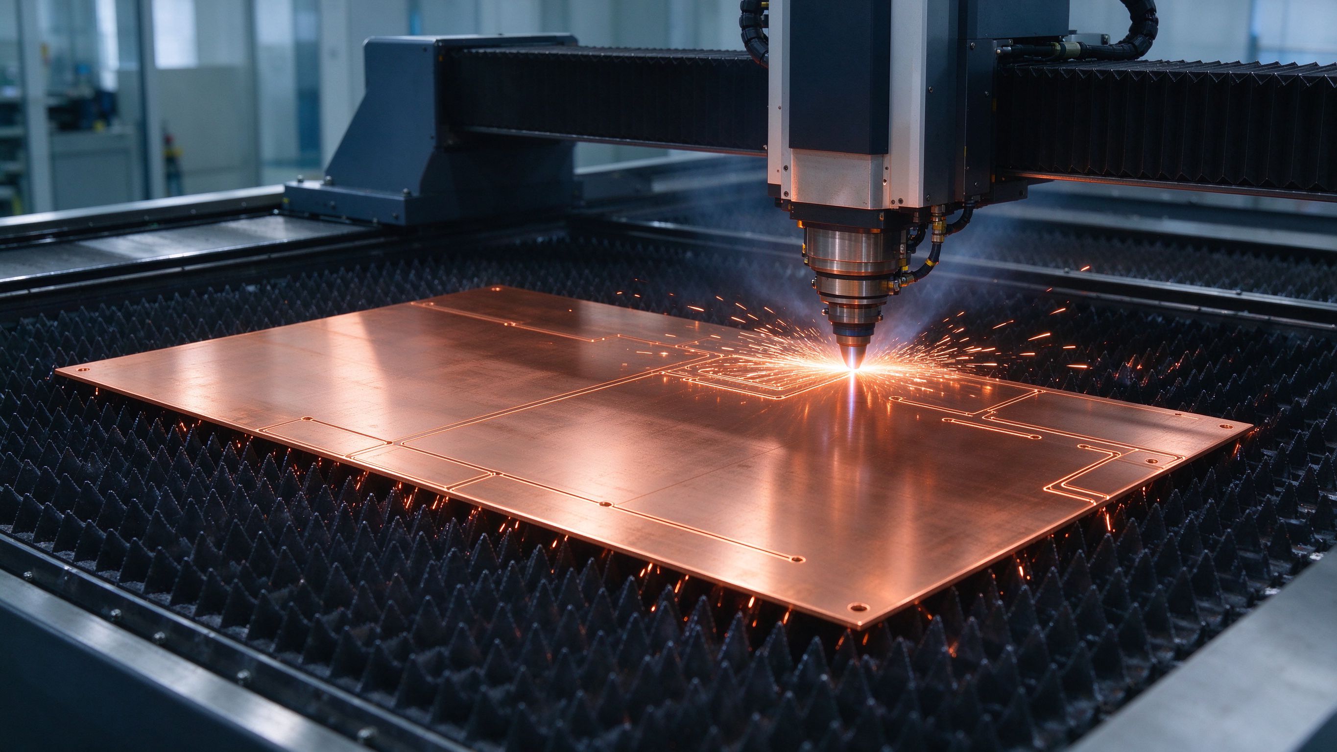
Laser-cutting terminal holes and stud windows on a busbar blank
Laser-cut terminal windows on a prototype busbar. Hole pitch, size and stud style are confirmed at DFM, not after first article.

5. Welding Zones and Plating Masking

Resistance or ultrasonic welding zones need to stay free of plating, because tin or nickel residues weaken the weld nugget. Before quote, mark on the drawing:

  • Exact weld zone outline (typically a 5–15 mm square around the weld point).
  • Whether the weld is on top, bottom or both sides.
  • Whether the weld tab is part of the copper blank itself or a separate welded-on piece.
  • Any place where a fuse link (controlled-neck copper) is intended as a weak point.

If a weld zone is not marked, we will plate the whole part, and the weld will be weaker. This is a cheap thing to get right and an expensive thing to discover after production. For context on what these joints have to survive, see inverter applications.

6. Current Path, Copper Width and Thermal Cycling

6.1 Current path continuity

  • Trace the current from input to output on every layer. Any sudden width narrowing acts as a hotspot.
  • Holes, slots and notches should not be placed directly in the main current path.
  • Corner radii at width transitions should be generous — sharp corners are stress-risers under thermal cycling.

6.2 Thermal cycling margin

Busbars in EV inverters, ESS and PCS applications see thousands of thermal cycles. Copper expands and contracts; the dielectric does not. Over years, repeated cycling can loosen a bolted joint or flex a weld. DFM checks that matter:

  • Enough slack/flex in the run between two stiff bolted points to absorb differential expansion.
  • Terminal torque values and washer choices confirmed (see terminal guide).
  • Current density sized for the 30 °C rise reference with derating — see current capacity article.
Mechanical isolation: If the busbar bolts to a heavy chassis on one end and to a vibrating IGBT stack on the other, include a flexible section or a slotted hole pattern. Rigidly clamping both ends is the classic field-failure mode.

7. Vibration, Mounting Holes and Fixturing

Finally, the mechanical side:

  • Mounting holes and support points are on the drawing, not just implied.
  • Stand-off height from the PCB or chassis is called out so the part fits mechanically.
  • Long, unsupported spans are avoided (vibration resonances) or supported.
  • Any plastic bracket, support block or clamp is shown, because it affects edge clearance.
  • Part orientation in service is noted (horizontal/vertical changes cooling — see ampacity chart).

When all of the above is on the drawing, our DFM review is short, the custom busbar quote is accurate the first time, and samples land in 5–7 working days. When it is missing, we will come back with questions — which is helpful, but it costs time you would rather spend building.

Ready to send a drawing? Email busbar@shanyo.com, or use /contact/. We are a dedicated busbar OEM and busbar supplier based in Rizhao, Shandong, shipping worldwide by sea or air. Browse our design guide and the busbar design guide for more depth.

7.1 Drawings, formats and what we prefer to receive

DFM goes faster when the drawing itself is complete. We accept PDF, STEP and Gerber-style exports, and we prefer a layered PDF where each copper layer is on its own named layer. Stack-up notes (copper thickness, dielectric type and thickness, plating, edge seal) should sit on the drawing title block, not in an email thread. Dimension tolerances matter: general tolerance blocks let us build efficiently, while call-outs on critical terminal pitch and hole positions let us inspect the right features. If you have a mating connector or lug on the customer side, include its part number — that single detail catches a surprising number of terminal-pitch mistakes before tooling is cut.

7.2 What happens after DFM sign-off

Once DFM is agreed, we cut the first article by laser (no hard tooling), build a small sample batch, run the full test battery — dimensional, visual, hipot, insulation resistance and continuity — and ship the sample with a factory test report. That sample is what your engineering team bench-tests before we commit to production tooling. After sample approval, stamping dies are built and mass production runs 2–3 weeks. There is no sample MOQ, which means you can start a new platform with one or two prototype parts without a production commitment. This is the flow we use for EV, ESS and industrial inverter customers, and it is the standard flow described on the custom busbar services page.

7.3 Common feedback we give back in DFM

A short list of the revisions we most often propose: widen a narrow neck in the current path to drop hotspot temperature; add a 5 mm film overhang where the drawing showed copper-to-copper edge; move a weld tab 10 mm away from a plated area; add a slot or flexible section between two rigid bolted points; and split a very long unsupported run with an extra mounting hole. Each of these is a 5-minute change on a CAD file and a multi-week fix in production. That is the whole reason we run DFM for free before quoting — it costs us a couple of hours of engineering time and saves the customer months of iteration.

We see customers every week who send a drawing with good electrical design but missing the small manufacturing details — weld-zone masks, stud style, edge margin — and then wonder why the first quote comes back vague. Thirty minutes on this checklist before you press send usually turns a back-and-forth quote into a single-pass price. If you want a second pair of eyes on a drawing before you release it to the wider market, send it to busbar@shanyo.com; we will run the DFM review for free, even if you are still comparing suppliers. As a focused busbar OEM, our job is to make the build as simple as possible for you, and DFM is where that starts.

7.4 A one-page pre-email checklist

Before you hit send on the drawing, walk through this one-liner list: layer count named, copper and dielectric thickness on the title block, every exposed edge has film overhang, creepage meets voltage class, terminal hole sizes match the fastener, stud vs blade vs weld tab vs fuse link is drawn, weld zones masked from plating, current path has no sharp corners in the neck, mounting holes and stand-offs are called out, and the worst-case hotspot temperature is written down. If all ten are on the PDF, your custom busbar quote will come back firm and fast. If three or four are missing, expect questions — and a slightly longer timeline. That is not us being pedantic; it is what separates a quote you can build from a quote you have to revise three times.
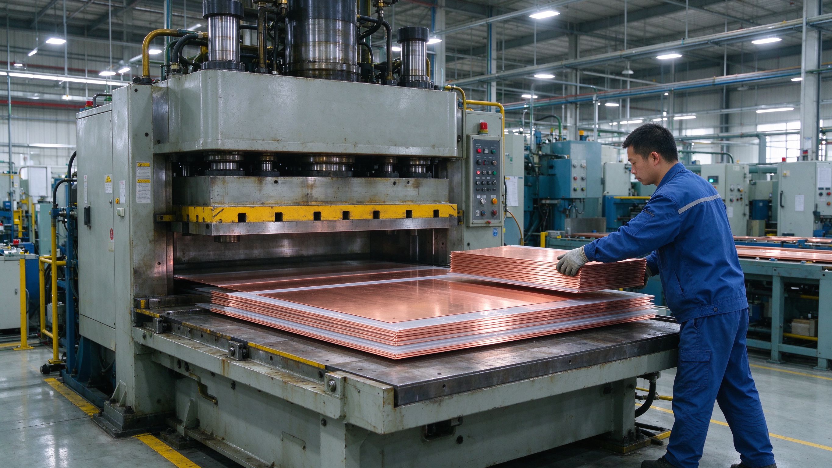
SHANYUAN runs a DFM review on every drawing before issuing a custom busbar quote.
Default buildC11000 copper, tin-plated, PET/Nomex/DLF dielectric, full edge seal, 1–6+ layers.
Standard terminalsM6/M8 studs, blade tabs, weld tabs, fuse links.
Samples ship in 5–7 working days; mass production 2–3 weeks; no sample MOQ.
FactoryRizhao Shanyuan Electronic Components Co., Ltd., Wulian Street, Rizhao, Shandong, China; founded 2012.
FAQ

Frequently asked questions

Why should I do DFM before asking for a custom busbar quote?
Because a quote built on an unclear drawing is an optimistic placeholder, not a price. A 30-minute DFM pass on layer count, edge margins, creepage, terminal spacing and weld zones usually prevents 2–3 revision cycles and turns a 'maybe' price into a firm one. SHANYUAN runs this review for free as part of quoting — see <a href="/custom/">custom busbar services</a>.
What drawings do you need to start a DFM review?
A PDF or STEP file of the busbar assembly, with layer stack-up, copper thickness, dielectric choice (or 'please recommend'), terminal styles, hole sizes, plating requirements and any current/voltage envelope. If something is not specified, we will propose it during DFM and quote accordingly.
Do you offer DFM feedback even if I am still comparing suppliers?
Yes. We treat the DFM call as engineering support, not as a commitment to order. If you are comparing laminated busbar price across three suppliers, the supplier that actually points out a creepage miss on your drawing is the one most likely to build it correctly the first time. No sample MOQ applies, and samples ship in 5–7 working days.
What are the most common DFM mistakes you see on customer drawings?
(1) Missing layer definitions; (2) no welding-zone masking, so plating goes where a weld needs to be; (3) terminal holes without saying whether they are clearance holes, press-in studs or welded studs; (4) sharp corners in the current path that become thermal-cycle stress risers; (5) rigid clamping at both ends with no flex for differential expansion. Catching these before quote saves weeks.
How do I contact SHANYUAN for a DFM review and quote?
Email busbar@shanyo.com, message on WhatsApp +1 519 253 9195, or call +86 136 4542 9121. You can also use the web form at <a href="/contact/">/contact/</a>. We reply within one business day. As an experienced busbar manufacturer shipping globally, we support both sample runs and production volume, by sea or air.
Related

Continue reading

The Laminated Busbar Manufacturing Process: A Step-by-Step Engineering Walkthrough
Manufacturing

The Laminated Busbar Manufacturing Process: A Step-by-Step Engineering Walkthrough

From C11000 copper coil to a fully sealed, tested multi-layer busbar, this walkthrough exp

Read article
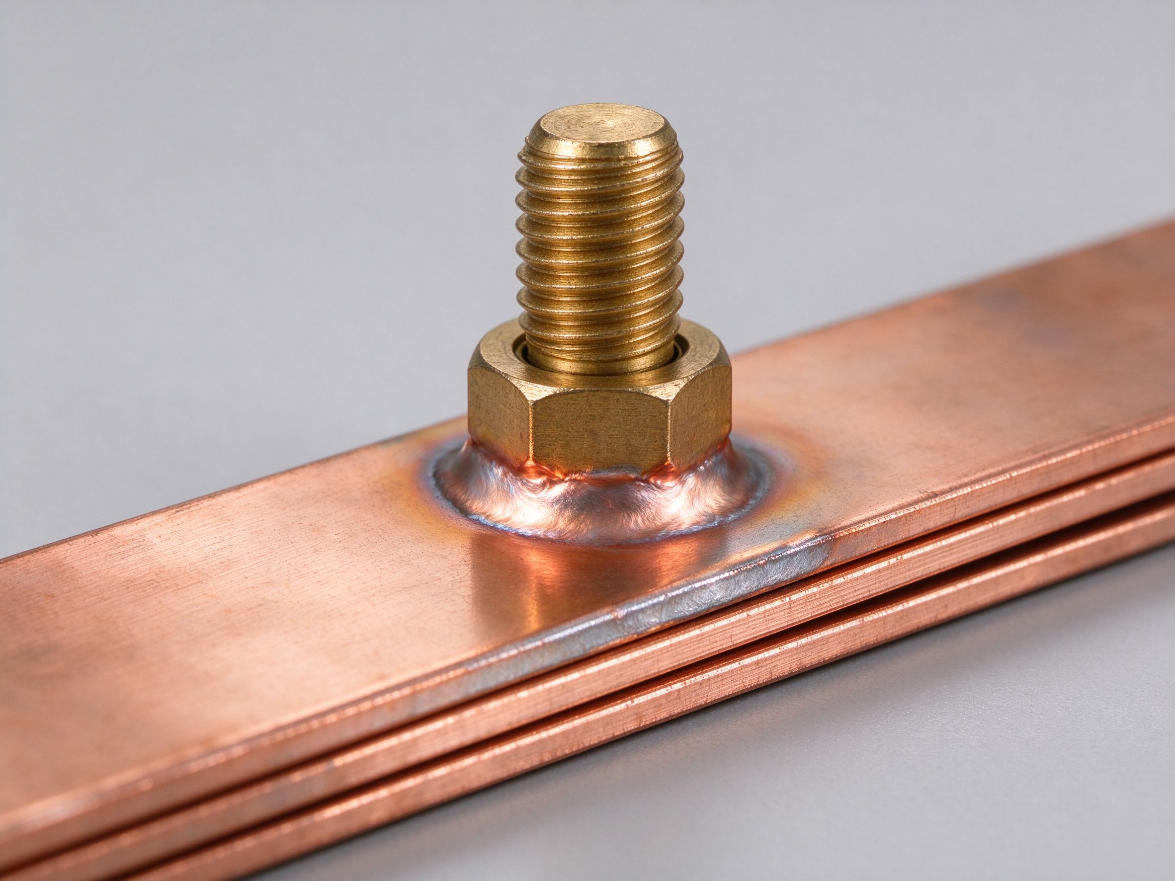
Busbar Terminal Types and Connections: Stud, Blade, Weld Tab and Fuse Link
Terminals

Busbar Terminal Types and Connections: Stud, Blade, Weld Tab and Fuse Link

The terminal is where a laminated busbar meets the outside world. This guide covers M6/M8

Read article
Busbar Current Capacity Explained: Ampacity, Temperature Rise and Derating
Design

Busbar Current Capacity Explained: Ampacity, Temperature Rise and Derating

Copper busbar current rating is not a single number. It is a starting ampacity adjusted by

Read article
SHANYUAN Engineering Team Rizhao Shanyuan Electronic Components Co., Ltd. — laminated busbar manufacturer, Shandong, China. Engineering notes reviewed against our production process and DFM records.

Designing a busbar for this application?

Send the current profile, voltage class and terminal types — our engineers reply within one business day.

Talk to our engineering team

Send drawings, current ratings and voltage class — DFM feedback and a quotation within one business day.

Send an InquiryWhatsApp