Floating and offshore solar are moving beyond sheltered reservoirs. In 2025 the world added 692 GW of renewable capacity, with a record 510 GW from solar, while coastal projects such as the 1 GW HG14 Bohai Sea array and the 400 MW Rudong solar-hydrogen-storage plant demonstrate gigawatt-scale water-borne generation. Salt aerosol, condensation and immersion cycling do not affect panels alone; they attack the copper busbars in combiners, inverters, storage converters and shore-based booster stations. Chloride raises contact resistance, joints heat up under I squared R loss, and 1500 V DC designs raise insulation and clearance requirements. This article reviews the 2026 project pipeline, contrasts reservoir floating, mudflat and open-sea architectures, and sets out the materials, plating, insulation, enclosure and procurement clauses that keep a marine-grade PV busbar reliable over a long service life.
Floating and offshore solar are moving beyond sheltered reservoirs. In 2025 the world added 692 GW of renewable capacity, with a record 510 GW from solar, while coastal projects such as the 1 GW HG14 Bohai Sea array and the 400 MW Rudong solar-hydrogen-storage plant demonstrate gigawatt-scale water-borne generation. Salt aerosol, condensation and immersion cycling do not affect panels alone; they attack the copper busbars in combiners, inverters, storage converters and shore-based booster stations. Chloride raises contact resistance, joints heat up under I squared R loss, and 1500 V DC designs raise insulation and clearance requirements. This article reviews the 2026 project pipeline, contrasts reservoir floating, mudflat and open-sea architectures, and sets out the materials, plating, insulation, enclosure and procurement clauses that keep a marine-grade PV busbar reliable over a long service life.
2025 was a record year for renewables worldwide. The International Renewable Energy Agency (IRENA) reports that 692 GW of renewable capacity was added during 2025, taking the global installed total to 5,149 GW, a 15.5% year-on-year increase; solar alone contributed a record 510 GW of additions while wind contributed about 159 GW (IRENA, Renewable Capacity Statistics 2026). On land, utility-scale PV competes for rooftops, deserts and agricultural fields; near water, a second frontier opened: photovoltaic arrays installed on reservoirs, mudflats, tidal shallows and, increasingly, open coastal seas.
Floating photovoltaics (FPV) and fixed offshore coastal PV convert a surface that usually carries little generation value into a power plant. The World Bank conservatively assessed the technical potential of FPV on man-made freshwater reservoirs alone at more than 400 GWp, before any coastal or saltwater expansion (World Bank, Where Sun Meets Water: Floating Solar Market Report, 2019). The segment remains small relative to ground-mounted solar but its growth rate is among the highest in the power sector, and the electrical balance-of-system hardware that carries the current strings to grid connection is where early design decisions are usually under-specified. The conductor assembly at the heart of that hardware is the busbar, whether as a laminated DC-link inside the inverter, a copper combiner rail in the string box, or an AC distribution bar feeding the onshore step-up transformer. This article maps the 2026 project pipeline to the conductor requirements it creates, starting with architecture, then corrosion, materials, insulation, current routing, and finally the procurement specification a buyer should write. Related background on the broader product cycle appears in the laminated busbar market outlook for 2026.
Reports often lump 'floating solar' and 'offshore solar' together, but engineers should separate three architectures because each stresses the conductor system differently. The first, classic reservoir FPV, mounts modules on high-density polyethylene (HDPE) floats anchored to lakes, quarry voids and irrigation reservoirs; the water is fresh or mildly brackish, humidity is high, but wave loading and spray are modest. The second, tidal-flat and mudflat PV, fixes panels on driven steel piles over intertidal zones such as the Jiangsu coast, where the array alternates between immersion, wet spray and sun baking through each tide cycle. The third, fixed open-sea coastal PV, uses steel platforms and piles in shallow continental-shelf water, where persistent salt aerosol, swell and galvanic seawater exposure apply the most severe environment.
Across all three, the electrical chain repeats: modules in series strings, DC collection wiring, fuse and string combiners, one or more power conversion stages, an AC low-voltage or medium-voltage bus, and an onshore booster or substation. Voltage classes have climbed toward 1500 V DC in modern utility arrays, so insulation thickness, creepage distances and clearance distances on DC busbars matter more than in legacy 1000 V designs; the design rules behind those distances are detailed in creepage and clearance design guidance. Conductor cross-section, plating and enclosure protection then follow the exposure class: a humid freshwater reservoir tolerates solutions that a splashed, salt-laden coastal platform does not.
The scale step-up is best read through three commissioned or advanced projects. In late December 2025, China Energy Investment Corporation connected its HG14 offshore PV facility near Dongying, in the Bohai Sea roughly eight kilometres off the Shandong coast. The 1 GW plant was built on 2,934 fixed steel platforms driven into the shallow seabed and carries more than 2.3 million panels over about 1,223 hectares; it was reported at approximately US$1.2 billion, and it is more than six times the size of the previous record-holder, the 150 MW Three Gorges New Energy floating array on an Anhui collapsed-coal-mine lake (Solar Now / Energies Media, 2026). HG14 demonstrates that offshore PV can reach gigawatt scale, and that every deck, inverter bay and booster cabinet must be engineered for salt air as a baseline condition, not a corner case.
On 10 June 2026, the Guohua Investment Jiangsu Rudong solar-hydrogen-storage demonstration plant was completed on coastal mudflat. Its 400 MW PV station sits alongside a 220 kV shore-based booster station, an electrochemical energy-storage plant and a dedicated electrolyzer rated at 1,500 standard cubic metres of hydrogen per hour; it was described as China's largest integrated offshore PV, green-hydrogen and storage closed-loop project (Seetao, 2026). The project shows the fusion of three DC-heavy loads on one coastal site, which multiplies the demand for robust DC distribution hardware. A separate CNNC Tianwan tidal-flat PV demonstration in Lianyungang, reported in October 2026 at 2 GW with a co-located 200 MW / 400 MWh battery facility, reinforces the same pattern: coastal PV is increasingly paired with storage and converter stations that depend on high-current busbars (Sina Finance, 2026). The DC power-electronics interface behind such schemes is covered in PCS DC-link busbar design, while the green-hydrogen side is covered in electrolyzer busbar requirements and the storage side in battery energy storage busbar systems.
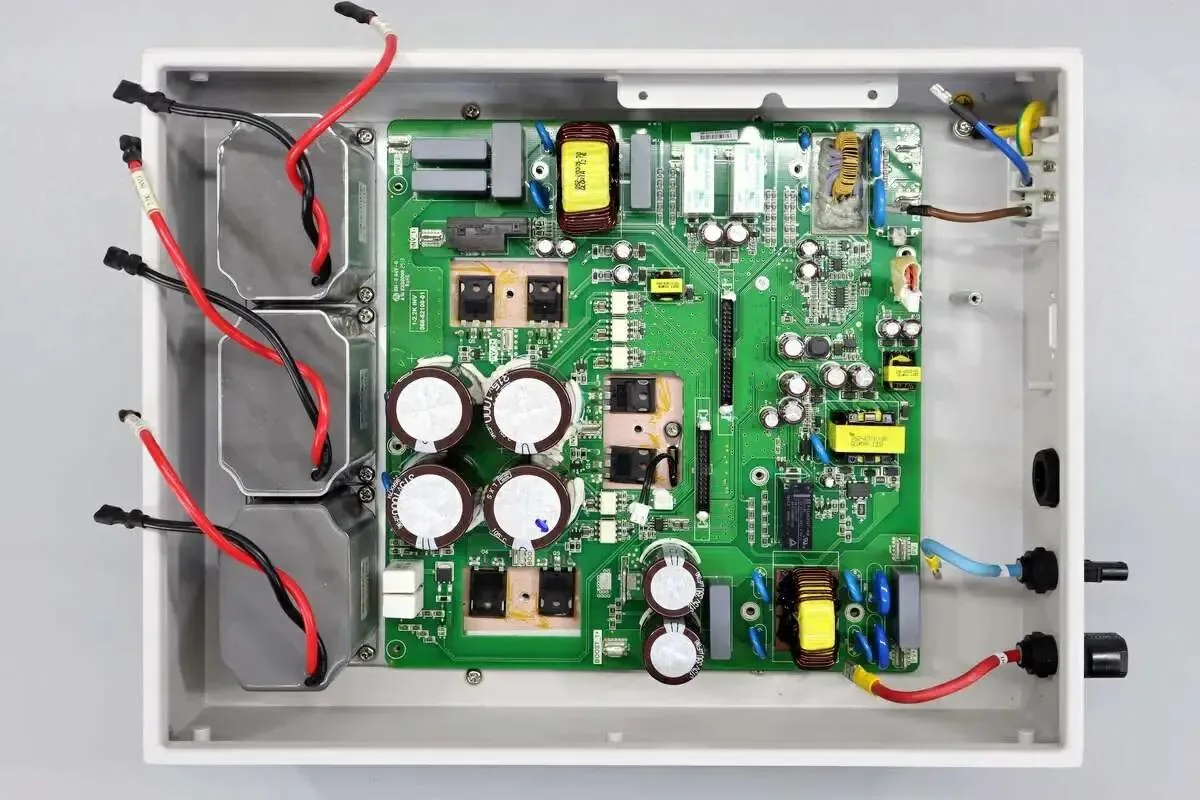
A solar busbar never performs one job; it performs several in series. At the string-combiner level, parallel module strings are joined on copper or aluminum rails through fuses, DC breakers and surge-protective devices, so the combiner busbar must carry the summed string current with even current sharing and low contact resistance at every terminal. Inside the central inverter or string inverter, laminated DC-link busbars connect capacitors, power semiconductor modules and the output winding path; their job is low parasitic inductance and uniform current distribution under switching transients, a role discussed alongside the inverter product segment in solar inverter busbar trends for 2026. On the AC side, LV distribution busbars feed the filter, the transformer primary winding and the switchgear breaker.
Two practical shifts shape these designs. First, replacement of bulky cable harnesses with rigid or laminated busbars shortens current paths, lowers inductance and reduces maintenance points; the engineering trade-off against cabling is laid out in busbar versus cable harness selection. Second, modern multi-layer laminated constructions stack positive, negative and earth layers with interleaved dielectric to cancel loop inductance; choosing the layer count and copper thickness for a given inverter rating follows the criteria in multi-layer laminated busbar selection. In large coastal plants the final AC bus at the shore-based booster station also sees high continuous current, enclosure heating and thermal cycling, so the rating methodology should be fixed before fabrication rather than reverse-engineered after a hot cabinet appears.
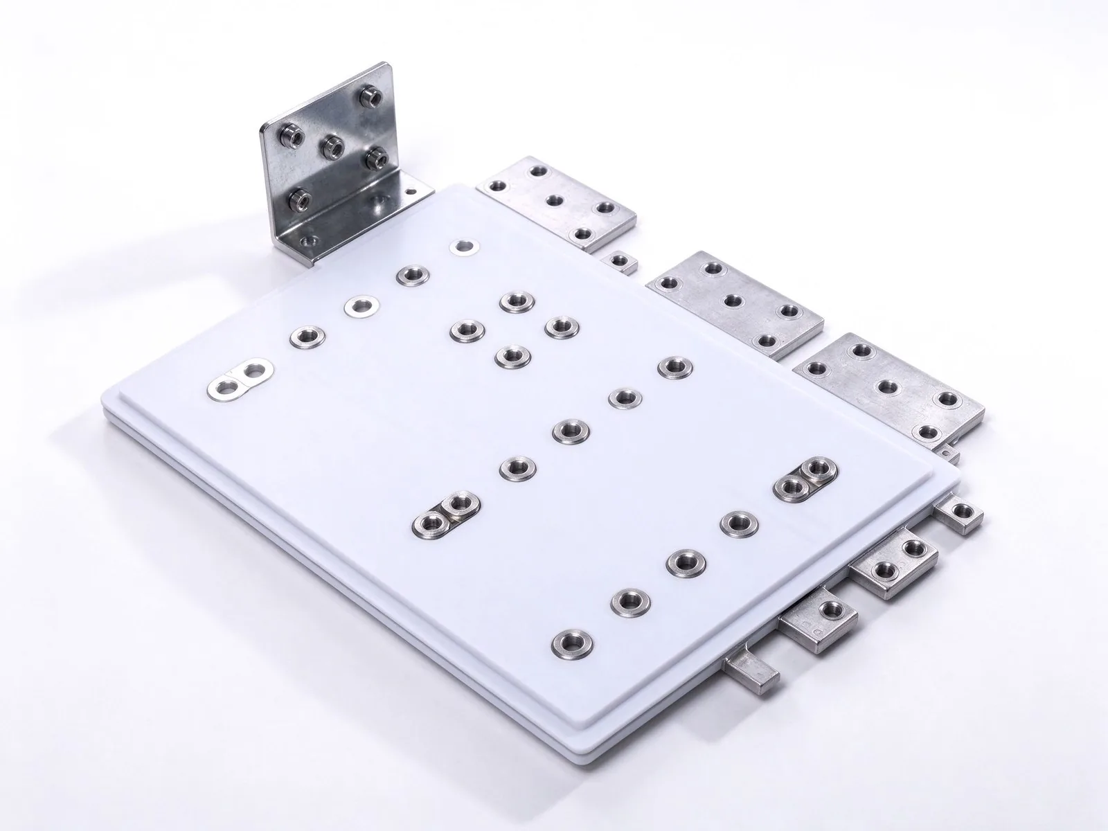
Marine air carries fine droplets and aerosol rich in sodium chloride (NaCl); when that moisture condenses on a metal surface it forms a thin, electrically conductive electrolyte. The US Department of Energy's Federal Energy Management Program identifies three corrosion modes relevant to PV balance-of-system hardware: oxidation, in which a metal loses electrons in the presence of oxygen and moisture; galvanic (dissimilar-metal) corrosion, in which two different metals coupled electrically through an electrolyte develop an anode and a cathode; and crevice corrosion trapped under contact faces, fasteners and insulation edges (US DOE FEMP, Managing and Mitigating Solar PV Corrosion, 2026). Frames and racks are the visible casualties, but the electrical consequences appear inside cabinets on lugs, terminals, fasteners and conductor surfaces.
On copper busbars, oxidation and chloride attack raise surface and contact resistance; because dissipation at a joint equals I squared R, that resistance converts directly into local heating and accelerates further degradation. Loose or corroded connections are a leading reason for fire risk and efficiency loss in PV arrays, which makes preventive inspection of terminals a specified maintenance activity in the cited guidance. Module-level salt exposure is commonly qualified under IEC 61701 salt-mist severity levels, with Level 6 reserved for severe marine-adjacent sites, and the same exposure logic should be carried into the electrical balance-of-system specification. Busbar-level corrosion protection strategies, plating choices and inspection practice are expanded in busbar plating and corrosion protection guide, and humid-environment insulation design is treated in outdoor and humidity busbar insulation guide.
Annealed C11000 (ETP) copper remains the default conductive material for renewable busbars because its combination of conductivity, ductility and weldability supports stamped, bent and laminated constructions; aluminum remains a cost and weight alternative in ventilated, lower-risk sections, but its oxide film and higher joint sensitivity demand more careful surface preparation, as compared in the copper versus aluminum busbar analysis for 2026. In marine service the bulk material matters less than the contact surface: the joint between two bars, between a bar and a stud, or between a bar and a lug is where corrosion-initiated resistance appears.
Tin plating is the mainstream compromise for outdoor and coastal copper terminals: it seals the underlying copper against atmospheric oxidation and chloride attack, provides a stable contact face under bolted pressure, and tolerates the temperature cycles between daytime load and night cooling. Silver or nickel plating may be specified where extremely stable contact resistance or higher temperature tolerance is required, at a clear cost premium. Designers should also control galvanic couples deliberately: copper or tin-plated copper near stainless fasteners and aluminum frames needs isolation washers, insulating sleeves and anti-oxidant joint compound where surfaces meet, following the dissimilar-metal caution documented in the DOE guidance. Surface finishes, edge treatment and coating options are summarized in busbar insulation and surface material procurement guide and busbar surface insulation coating guide. A corrosion-resistant terminal choice at the ends of the bar is equally important; common families and their sealing methods are compared in busbar terminal type selection guide.
Coastal cabinets are humid most of the time even when dry-looking. Condensation forms when daytime solar heating warms enclosed air and night cooling drives dew onto internal surfaces; salt deposit films are hygroscopic and hold that moisture against the insulation. Laminated busbars use dielectric films between copper layers, commonly PET (polyester), Nomex aramid paper or dedicated DLF dielectric laminates, chosen for dielectric strength, thermal class, peel adhesion and ability to survive bending and lamination; the selection criteria are detailed in busbar dielectric material selection guide. The external insulation on exposed outer layers should be continuous, with sealed edges at machined holes and stamped cutouts, because salt-laden moisture creeping into a film edge can delaminate the insulation from the copper over several seasons.
Enclosure protection should be set from the exposure class rather than habit. Outdoor coastal combiner and inverter cabinets are commonly expected to meet at least IP67 against temporary immersion and splashing, with IP68 preferred for low-mounted or frequently wetted equipment; internal electronics benefit from conformal coatings on PCBs and from non-conductive protective sprays on lugs and connectors, consistent with the mitigation measures in the DOE guidance (US DOE FEMP, 2026). Desiccant breathers, drain-free sealed compartments and internally coated steel enclosures round out the design. Finally, insulation must remain dielectrically intact after years of humidity: routine insulation-resistance and dielectric checks belong to commissioning and warranty protocols, complemented by the methods in busbar insulation testing guide.
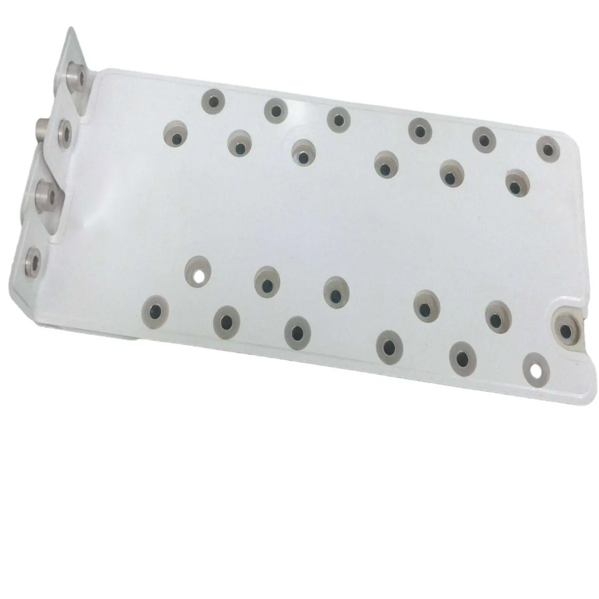
Utility PV arrays at 1500 V DC send large, continuous currents through compact converter bays, and three electrical targets govern the routing. First, ampacity: the copper cross-section must hold a safe temperature rise under rated current with the enclosure's real convection, not the free-air rating from a textbook table; sizing logic is set out in busbar ampacity calculation guide. Second, voltage drop: excess resistance in combiner and DC-link bars wastes energy as heat and depresses the DC voltage seen by the inverter, and the loss calculation behind that statement is developed in busbar voltage drop and power loss guide. Third, inductance: switching devices such as IGBT and SiC modules commutate rapidly, and high loop inductance creates voltage overshoot and switching loss, which is why laminated positive-negative pairs are preferred over spaced flat bars; the magnetic side of that choice appears in busbar loop inductance measurement guide.
For coastal plants the thermal target should be conservative. Cabinets on an open deck bake under summer sun; sealed combiners have little airflow; and derating for enclosure temperature, altitude and harmonics should be applied before the final cross-section is chosen. Current sharing between parallel bars or parallel layers must be balanced by symmetric geometry and equal-length paths, because an unevenly shared current concentrates heating on one phase; the design measures are described in busbar current sharing design guide. A busbar that looks oversized on paper may still run hot if its joints are small, its plating oxidizes, or its cabinet traps heat, so the final rating should be validated by a measured temperature-rise test rather than by calculation alone.
Modern coastal PV projects rarely stand alone. Battery energy-storage systems (BESS) smooth intermittency and provide peak shaving; electrolyzers absorb surplus power to produce green hydrogen; and microgrid and station-auxiliary loads feed from the same DC or low-voltage DC backbone. Each addition changes the busbar duty cycle: a battery rack bar carries charge and discharge current in both directions, frequently at rates close to its continuous rating, and must tolerate frequent cycling without loosening plated joints; the system-level picture is presented in C&I storage and microgrid busbar demand and long-duration energy storage busbar systems. Fire-safety regulation also shapes the insulation and enclosure materials in energy-storage halls, as summarized in ESS fire-safety regulation and busbar requirements.
Electrolyzers push a large DC current, often through tightly packed rectifier outputs and cell stacks; their busbars combine high amperage, repeated thermal cycling and sometimes corrosive process environments nearby, while safety clearances follow the electrolyzer electrical architecture. The combined effect for an EPC or procurement team is that the PV-side busbar specification should not be written in isolation: the cabinet may host both inverter and storage interfaces, and one conductor run may need to satisfy the more demanding duty among the co-located loads. Supplier evaluation should therefore ask for bidirectional-current capability evidence, cycling tolerance data and, where relevant, compatible protection coordination rather than treating each busbar as a one-off piece of copper.
A coastal PV busbar specification should be written as a set of verifiable clauses rather than adjectives. Start with electrical ratings: maximum continuous current, DC system voltage (for example 1000 V or 1500 V), required short-time withstand current and duration, target voltage-drop budget per run, and the enclosure ambient at which the rating applies. Then specify the conductor: alloy and temper such as C11000 copper, cross-section, number of laminated layers, insulation system (PET, Nomex or DLF), plating type and minimum thickness at exposed joint faces, and terminal family (stud, blade or welded lug). Environmental clauses should name the exposure category, required salt-mist qualification evidence, enclosure IP class, humidity range, and any anti-condensation measures.
Verification clauses convert the specification into evidence. Require a temperature-rise report at rated current inside a representative enclosure, dielectric withstand evidence, and dimensional and plating inspections; the checklist a buyer can use when scoring suppliers is compiled in busbar RFQ and supplier evaluation guide. Short-circuit behaviour should be addressed separately because a busbar that carries continuous current well can still fail electrodynamically during a fault; the test logic is explained in busbar short-circuit withstand guide. Drawings, tolerances and acceptance sampling should follow a disciplined design-for-manufacturing review, captured in the 2026 busbar DFM checklist. Buyers who omit the verification clauses usually discover overheating joints after installation, where remediation costs several times the busbar price.
SHANYUAN (Rizhao Shanyuan Electronic Components Co., Ltd.) was founded in March 2012 and operates a 17,200 m² manufacturing plant at Taoyuan Village, Wulian Street, Rizhao, Shandong, China; products from the facility are exported to more than 20 countries. The core product family covers insulated laminated busbars with one to six or more layers, designed around approximately 1,000 A continuous-current classes, using C11000 copper with PET, Nomex and DLF dielectric systems, a conservative 30 °C design rise target, tin-plated contact faces, and M6 or M8 studs, blade terminals and welded terminal assemblies. The lamination, stamping, bending, welding and assembly sequence that turns copper strip and dielectric film into those assemblies is described end to end in the laminated busbar manufacturing process guide, and modern line organization for repeatable output is covered in automated laminated busbar production lines.
For renewable-sector buyers, the relevant capability points are repeatable plating and insulation bonding, consistent stud and terminal welding, and the ability to release each design only after dimensional and electrical checks. Prototype samples before mass production allow the layout, mounting holes and thermal behaviour to be refined on actual tooling; the sample-release workflow is described in busbar prototyping and quick samples guide. Material exposure to volatile copper prices and tariff movements should also be considered when fixing price validity and material reserve terms, as analyzed in copper price and busbar supply conditions in 2026. Engineering inquiries, drawings and rated-current questions can be sent to busbar@shanyo.com.
A tight RFQ reduces quotation variability. Include the single-line or block diagram showing where each busbar sits; rated continuous current and expected duty cycle (including any bidirectional storage or electrolyzer current); DC or AC nominal voltage and required dielectric withstand; enclosure type, IP class and maximum expected internal ambient; cooling method (natural convection, forced air or liquid); full load current profile if cycling; available mounting space, hole pattern and terminal spacing; plating and insulation requirements; required salt-mist or corrosion category; and target quantity with expected annual forecast and MOQ expectations. Drawings with tolerances are preferred over photographs because they define edge radius, hole positions and insulation overlaps.
On the way back, request: material certificate for the copper temper; plating thickness measurement; insulation material data sheet and dielectric test record; dimensional first-article report; a temperature-rise test report at the specified current and ambient; contact-resistance or joint-resistance record for bolted or welded interfaces; and, for qualified programs, short-time withstand evidence. Confirm that the supplier keeps revision-controlled drawings and can honor CoC (Certificate of Conformance) per shipment. The supplier-evaluation framework covering technical capacity, quality system, lead time and commercial terms is provided in trade-tariff and supply continuity considerations. Early prototype iterations, explained in the quick-samples guide, usually pay back by avoiding rework once series tooling is committed.
Three trends are likely to sharpen busbar requirements through 2027. First, DC system voltages and string currents continue to rise, pushing laminated constructions, low-inductance layouts and conservative insulation ratings into more inverter and combiner bays. Second, coastal hybrid plants that combine PV, storage, electrolysis and shore-based conversion become the default project model rather than the showcase, which means conductors must satisfy the worst of several duty cycles at once. Third, corrosion and environmental qualification move from optional marketing claims to contract requirements, mirroring the maritime-grade habits already used in offshore wind converters, whose environment-led conductor demand is analyzed in offshore wind converter busbar demand, and in marine shore-power applications reviewed in electric-ship shore-power busbar applications.
The practical conclusion for PV developers, EPCs and inverter OEMs is straightforward: the busbar should be specified as an engineered electrical component with a tested rating, a defined corrosion class and a documented insulation system, not as a cut length of copper with paint on it. Treat the joints, the plating and the enclosure as primary design objects, demand measured evidence in the tender, and reserve commercial and technical flexibility for prototype iteration. For SHANYUAN engineering support on a specific coastal or floating PV inverter, combiner or booster-station busbar design, contact busbar@shanyo.com with the project rating, architecture sketch and target enclosure.
The inverter that dominated 2026's solar tenders is no longer a small box: 300 kW-plus str
Read article
Outdoor busbar installations fail from humidity, salt and condensation long before they fa
Read article
The plating on a busbar contact is a corrosion strategy as much as a conductivity play. Ti
Read article
Emily Novak analyses energy-storage, grid and new-energy markets and turns them into procurement-ready technical content. With 7 years in energy market research and technical writing, she covers BESS growth, HVDC projects and regulatory shifts that change busbar demand. She holds an M.A. in Energy E
Send the current profile, voltage class and terminal types — our engineers reply within one business day.