Grid-scale energy storage crossed the 100 GW annual-addition mark in 2025, and every forecast published in 2026 points one direction: up. BloombergNEF projects 158-188 GW of new storage in 2026 (roughly 459-535 GWh), a 41-45% jump over the 2025 record, with China contributing more than half of global additions. Inside that surge, the power conversion system (PCS) is being redesigned around 1500 V DC buses, SiC-based converter stages and ever-denser cabinets - and the DC-link laminated busbar is the component that has to carry several hundred kiloamps of aggregate switching current across the fleet.
Grid-scale energy storage crossed the 100 GW annual-addition mark in 2025, and every forecast published in 2026 points one direction: up. BloombergNEF projects 158-188 GW of new storage in 2026 (roughly 459-535 GWh), a 41-45% jump over the 2025 record, with China contributing more than half of global additions. Inside that surge, the power conversion system (PCS) is being redesigned around 1500 V DC buses, SiC-based converter stages and ever-denser cabinets - and the DC-link laminated busbar is the component that has to carry several hundred kiloamps of aggregate switching current across the fleet.
BloombergNEF's Energy Storage Market Outlook (1H 2026) confirmed that global energy storage additions excluding pumped hydro reached 112 GW / 307 GWh in 2025, and the 2026 outlook published in October 2026 projects a 45% year-on-year surge to roughly 188 GW / 535 GWh, with 2027 expected to reach about 209 GW / 638 GWh. The growth is no longer China-only: Europe and Australia are forecast to roughly double their annual additions in 2026, and the long-range projection to 2036 stands near 308 GW per year.
For busbar suppliers the arithmetic is direct. Each gigawatt of battery storage contains thousands of battery racks, hundreds of PCS units and dozens of distribution cabinets. A typical 1500 V PCS module carries 200-500 kW; a 500 MW project therefore needs 1,000-2,500 modules, each containing at least one laminated DC-link busbar in the converter stage and additional busbars in the rack and string distribution. The storage boom translates into a sustained, multi-gigawatt-per-year pull on laminated busbar capacity.
The 1500 V DC architecture is now the default for utility-scale BESS. Compared with the older 1000 V systems, 1500 V reduces current for the same power, cutting cable and busbar copper mass, losses and system complexity. The trade-off is insulation stress: at 1500 V the industry must respect reinforced insulation coordination, which is precisely where laminated busbar construction earns its keep - interleaved conductor layers with controlled dielectric thickness manage the electric field locally, whereas field-assembled cabling leaves clearance and creepage to installation practice.
In 2026 the roadmap is moving again. Several vendors are developing 2000 V DC bus platforms to push current down further and exploit SiC device ratings; at 2000 V the insulation coordination burden (pollution degree, overvoltage category, partial discharge margin) becomes the dominant design constraint. Busbar dielectric selection therefore shifts from simple film wraps to engineered stacks validated for discharge-free operation at working voltage plus margin, following the logic of dielectric selection guidance.
Silicon carbide MOSFETs are displacing silicon IGBTs in the converter stages of grid-storage PCS platforms. The physics argument is familiar: SiC's critical field strength of roughly 3 MV/cm - about ten times that of silicon - allows a 1700 V-rated MOSFET to be built with a far thinner drift layer, cutting switching losses and enabling higher switching frequencies in a smaller package. Vendors report PCS conversion efficiencies above 99% on SiC-based platforms, with the residual losses concentrated in magnetic components and interconnects.
The DC-link consequence is a fast-switching, high-di/dt power stage. Fast switching shrinks the loss budget but increases the dV/dt stress on insulation and the di/dt stress on every loop inductance in the commutation path. A laminated DC-link busbar with interleaved layers keeps loop inductance in the low nanohenry range, directly limiting voltage overshoot across the SiC devices. This is why inverter DC-link busbar assemblies and IGBT/SiC module busbar sets are specified as standard on new PCS designs rather than as an afterthought.
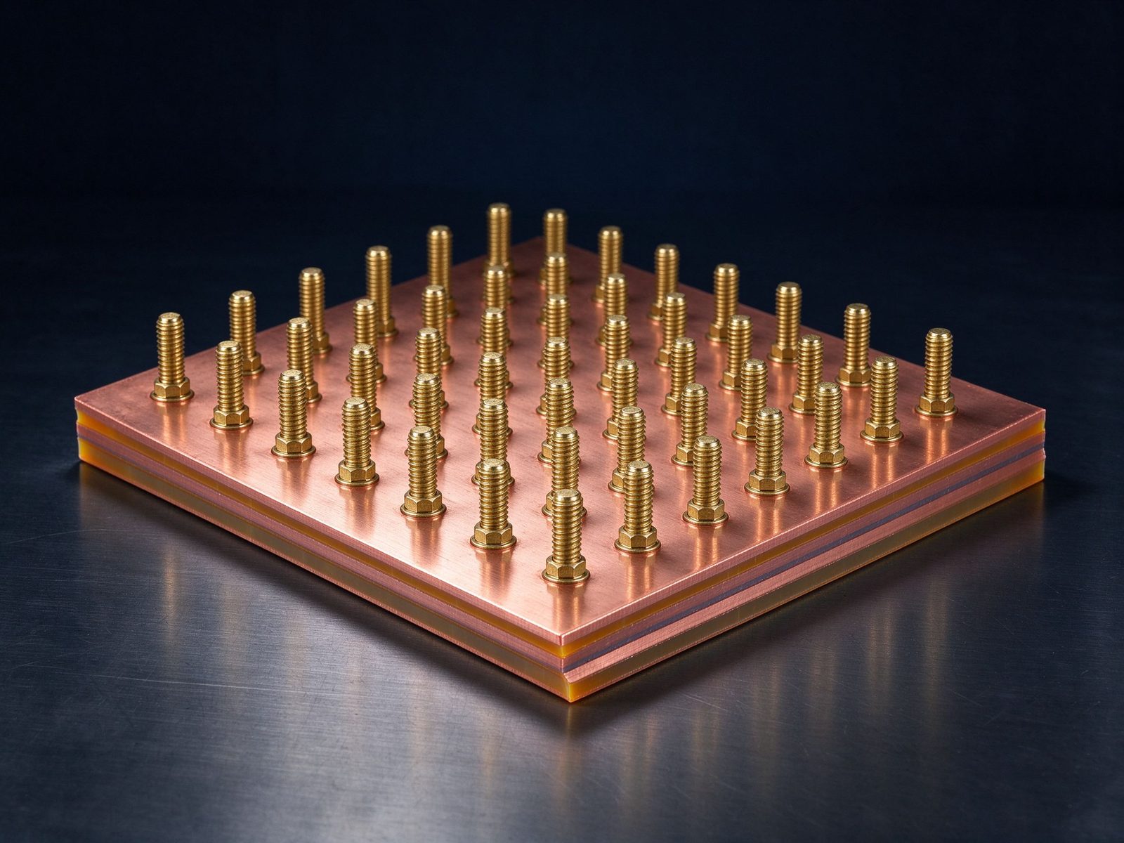
Round-trip efficiency (RTE) is the headline metric for storage asset owners, and 2026 designs are attacking it from both ends. DC-coupled solar-plus-storage configurations send PV power directly to the battery DC bus, eliminating one AC/DC conversion on the charge path and saving 2-4 percentage points on the solar-to-battery leg; commercial systems are quoted at 92% RTE and climbing. The DC-coupled architecture also changes the busbar map: the PV optimizer and the PCS share a common DC bus, which means the intermediate distribution bus carries both source and storage currents and has to be rated for the combined worst case.
For busbar design, DC coupling means more two-directional current paths, more paralleled converters and more points where a low-resistance joint matters. The thermal result is a bus that operates closer to its ampacity envelope for longer periods, which is why the same thermal management and derating disciplines that govern traction busbars now apply to stationary storage. A 30 °C rise at 40 °C ambient remains a sane baseline, with derating applied for enclosure airflow and rack bundling.
A utility-scale BESS decomposes into racks (typically 600-800 V DC per rack, 5-8 MWh per container), string-level protection, and the PCS. In most 2025-2026 designs the cell-to-pack interconnection and rack bussing use copper battery links and laminated assemblies rather than cables, because the rack bus must carry 300-600 A continuously in a confined, thermally coupled enclosure. Battery management system busbars, multi-terminal battery module busbars and high-current battery module busbars are the components that turn a cell stack into a rack with predictable voltage drop and thermal behaviour.
The rack-to-PCS connection is where the second generation of designs is consolidating: instead of individual cables per rack, containers now ship with laminated distribution rails integrating fuse, contactor and current-sensor positions. This consolidation reduces assembly time on site - a real cost when a 500 MW site has thousands of racks - and gives the owner a factory-tested interconnect instead of a field-routed harness. Power distribution practice for storage follows this same rail-based architecture.
| Parameter | 1000 V legacy | 1500 V mainstream 2026 | 2000 V emerging |
|---|---|---|---|
| DC bus voltage | 1000 V | 1500 V | 2000 V |
| Converter device | Si IGBT | SiC MOSFET (hybrid options) | SiC, reinforced insulation |
| Typical module power | 150-250 kW | 250-500 kW | 500 kW+ |
| Conversion efficiency | ~97-98% | 99%+ | target 99%+ |
| Insulation coordination | IEC 60664 basic | reinforced, PD-verified | PD-verified, tight margins |
| DC-link busbar | optional | standard laminated | mandatory laminated, low-inductance |
The table is a simplification, but the direction is unambiguous: every voltage step-up increases the role of the laminated DC link and raises the bar on dielectric and inductance verification.
PCS cabinets have been shrinking while power ratings climb, and the thermal budget inside a 500 kW SiC converter is measured in square centimetres of cold plate. The DC-link busbar sits at the centre of that thermal map: it conducts the switching current, spreads the module's losses, and is often the mechanical anchor for the power module stack. Thermal management design for PCS busbars therefore covers conductor sizing for both ampacity and heat spreading, low-resistance plating at every interface, and - at the top end - liquid-cooled or cold-plate-attached busbar assemblies.
Field data from liquid-cooled power electronics consistently shows that removing the busbar's heat reduces device junction temperature more than marginal improvements in the module itself, because the busbar is the only continuous thermal path between the devices and the cooling surface. Vendors of water-cooled laminated busbars report temperature reductions of 23-58 °C on the conductor itself when active cooling is added - a margin that translates directly into more delivered kilowatts per cabinet.
At 1500 V DC, insulation coordination follows IEC 60664-1 with the overvoltage category and pollution degree of the installation environment. The practical consequences for busbar stacks are threefold. First, clearance and creepage must be designed, not improvised: conductors must respect minimum distances that grow with rated voltage and pollution degree. Second, partial discharge must be engineered out: a void or a sharp edge inside the dielectric will discharge at operating voltage, and once discharge starts, erosion accelerates. Third, the test suite matters - impulse, AC power-frequency, PD and DC tests each catch a different weakness, and a complete set is standard on busbar insulation testing for storage products.
For 2000 V platforms these requirements tighten further. Reinforced insulation margins, edge fillets, controlled dielectric thickness and verified discharge-free performance are moving from recommended practice to contract requirements in utility tenders.
Utility storage projects are financed on 20-25 year performance assumptions, and component traceability is becoming a contractual expectation. Busbar suppliers for storage now routinely deliver material certificates, weld and plating process records, and inspection data per lot. At SHANYUAN, the quality system applies PPAP-style documentation to storage series orders: copper alloy certificates for C11000, dielectric certificates for PET/Nomex/DLF, thermal-cycling and hi-pot test reports per batch, and serial-level traceability for the high-current parts that carry the rack current.
For procurement teams, the practical checklist is short: ask for the test evidence before awarding, verify the ampacity rating method (30 °C rise baseline, derating factors), and confirm the terminal strategy matches the rack maintenance plan - because a bolted joint that must be re-torqued in the field is a different product from a welded assembly that is maintenance-free. The DFM checklist covers exactly these decision points.
Work a representative example to make the component requirement concrete. A 500 kW PCS module operates from a 1,500 V DC bus; at full power the DC-link current is about 333 A average, with switching ripple adding thermal stress beyond the DC average. On the AC side, a three-phase IGBT/SiC bridge draws phase currents of roughly 400 A RMS. The DC-link busbar between the module capacitors and the devices must therefore be rated above 400 A steady state with a low-inductance geometry - typically a 2-3 layer laminated assembly with 2-3 mm copper per conductor, interleaved planes, and a stack height kept under about 15 mm to fit the module envelope.
The capacitance network complicates the layout: DC-link capacitors are paralleled physically close to the devices, and the busbar must connect them with short, wide, interleaved paths. This is the classic inverter DC-link busbar problem - and it is why the busbar, not the capacitor, often sets the achievable inductance of the stage. Design reviews for PCS platforms therefore simulate the busbar loop inductance (target: tens of nanohenries or less) before the first prototype, using the same methods described in low-inductance design.
Storage hardware stacks busbars at four levels, each with different requirements. Cell level: thin copper links or laminated interconnects between cells, sized for the cell current and thermal budget, usually welded or bolted to the cell terminals. Module level: the module busbar that sums the cells and connects to the string, carrying 100-300 A with integrated sensing and fuse positions. Rack level: the vertical distribution rail that parallels modules, rated for the rack current and designed for assembly in the rack enclosure. Container level: the main DC distribution that ties racks to the PCS, where the current reaches thousands of amps and the bus moves from the rack to a dedicated distribution cabinet.
Each level has its own failure mode and its own test logic. Cell and module joints are welded or torque-controlled, and their resistance is verified per module. The rack rail is a laminated assembly with bolt access for maintenance, and its insulation must survive the rack's thermal environment. The container bus is the highest-current, most safety-critical part - it carries the full container current and must clear faults without softening, which is where copper cross-section, joint quality and the derating logic of the ampacity chart all converge.
The migration from 1,500 V to 2,000 V DC buses is the defining storage trend of the next design cycle. At 2,000 V, current drops another 25% for the same power, which cuts copper mass and loss - but the insulation burden grows disproportionately. Insulation coordination at 2,000 V demands higher creepage, reinforced margins, verified discharge-free dielectric performance, and a test suite that catches field stress before commissioning. PD testing at working voltage becomes non-negotiable, and the dielectric stack must be engineered for the field rather than selected from a catalogue.
For busbar suppliers the 2,000 V roadmap favours exactly the capabilities SHANYUAN builds on: controlled dielectric thickness, edge fillets, PD-verified stacks and documented test evidence. Buyers planning 2,000 V platforms should qualify suppliers on these engineering capabilities now, because retrofitting insulation margin later is far more expensive than designing it in - the argument made in the insulation testing guide.
Put the component requirements together with a representative 5 MWh container. Assume 20 racks at roughly 5 kWh per rack-layer, each rack running 650-800 V DC and carrying 250-350 A at the rack bus. The rack-to-string connection uses laminated distribution rails integrating fuse and contactor positions; the string combines four racks and runs 1,000-1,200 A to the PCS cabinet at 1,500 V. The container's main DC bus then parallels the strings into the PCS input, where the module DC links take over.
The current map shows why busbar copper dominates the container's metal budget: rack rails at 300 A class, string rails at 1,000 A class, and the main bus at 2,000 A-plus. Each level also has its own thermal environment - the rack enclosure is the hottest, the distribution cabinet is vented, and the PCS module is actively cooled. The same busbar family has to satisfy three different thermal budgets, which is why storage busbar programs standardise on the 30 °C-rise method with application-specific derating, as covered in thermal management design.
Lower current at the same power means less copper, lower losses and simpler systems; 1500 V is now the utility-scale default, with 2000 V platforms emerging.
SiC switches fast, so loop inductance must be minimised to limit dV/dt and di/dt stress; interleaved laminated layers cut inductance by 5-20x versus cabling.
A rough order: hundreds of PCS modules and thousands of racks per GW, each with one or more laminated DC-link and rack busbars - a sustained multi-GW pull on capacity.
At 1500-2000 V, partial discharge testing at working voltage is increasingly standard, following IEC 60664-1 and IEC 60270 practice.
See how the same DC-link disciplines apply in megawatt charging, where the market is headed in the 2026 busbar market outlook, and the engineering depth in insulation testing, thermal management and welding and joining.
In summary, 2026 storage procurement converges on a single checklist: 1500 V architecture as the baseline, 2000 V on the roadmap, SiC in the converter, and a laminated, PD-verified, low-inductance DC link as the component that makes the efficiency numbers real.
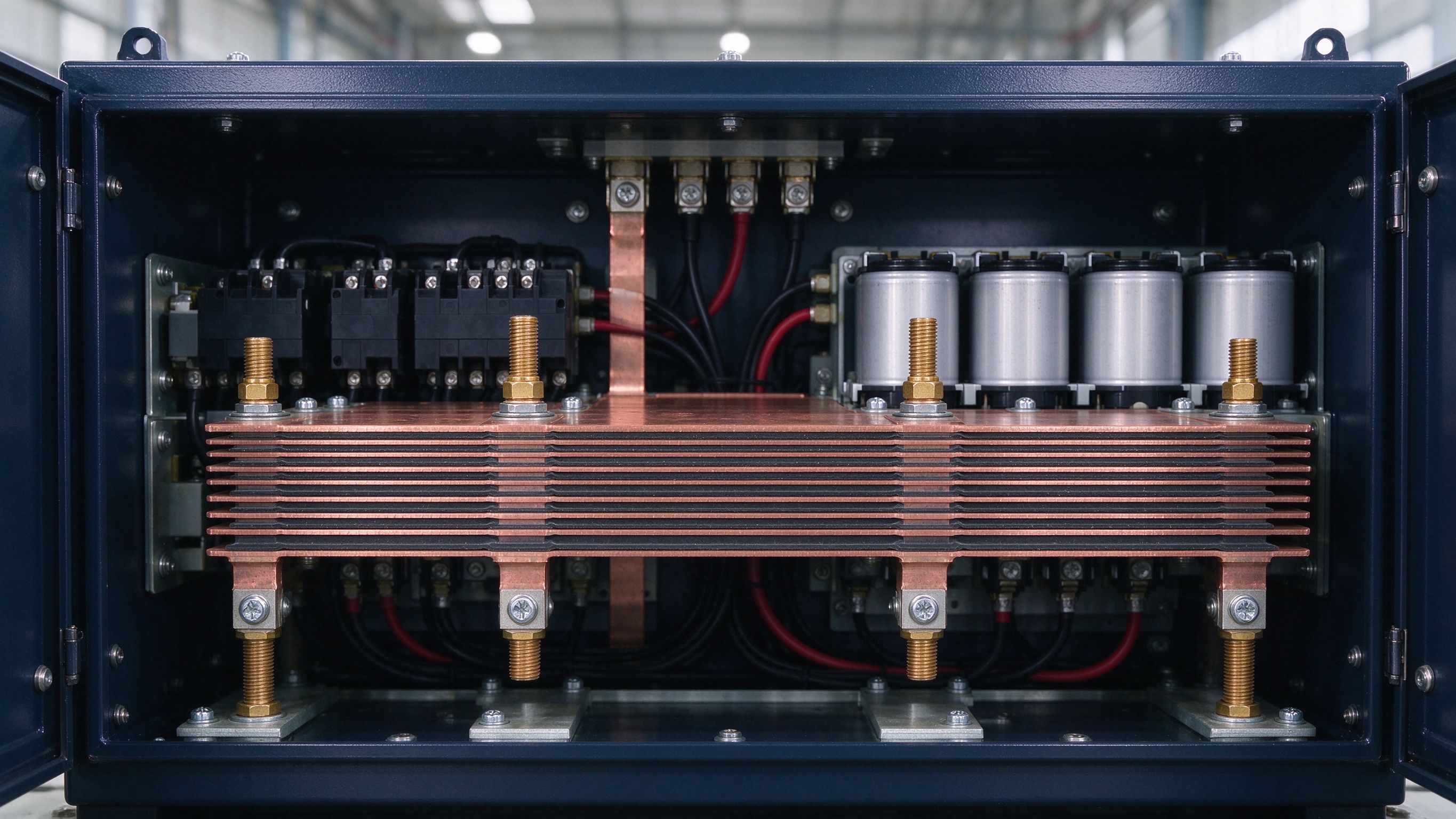
MCS moves from pilot to fleet scale in 2026: 1 MW+ charging at 1250 V and up to 3000 A mak
Read article
Multiple forecasters put the laminated busbar market near USD 1.0-1.06 billion in 2026, wi
Read article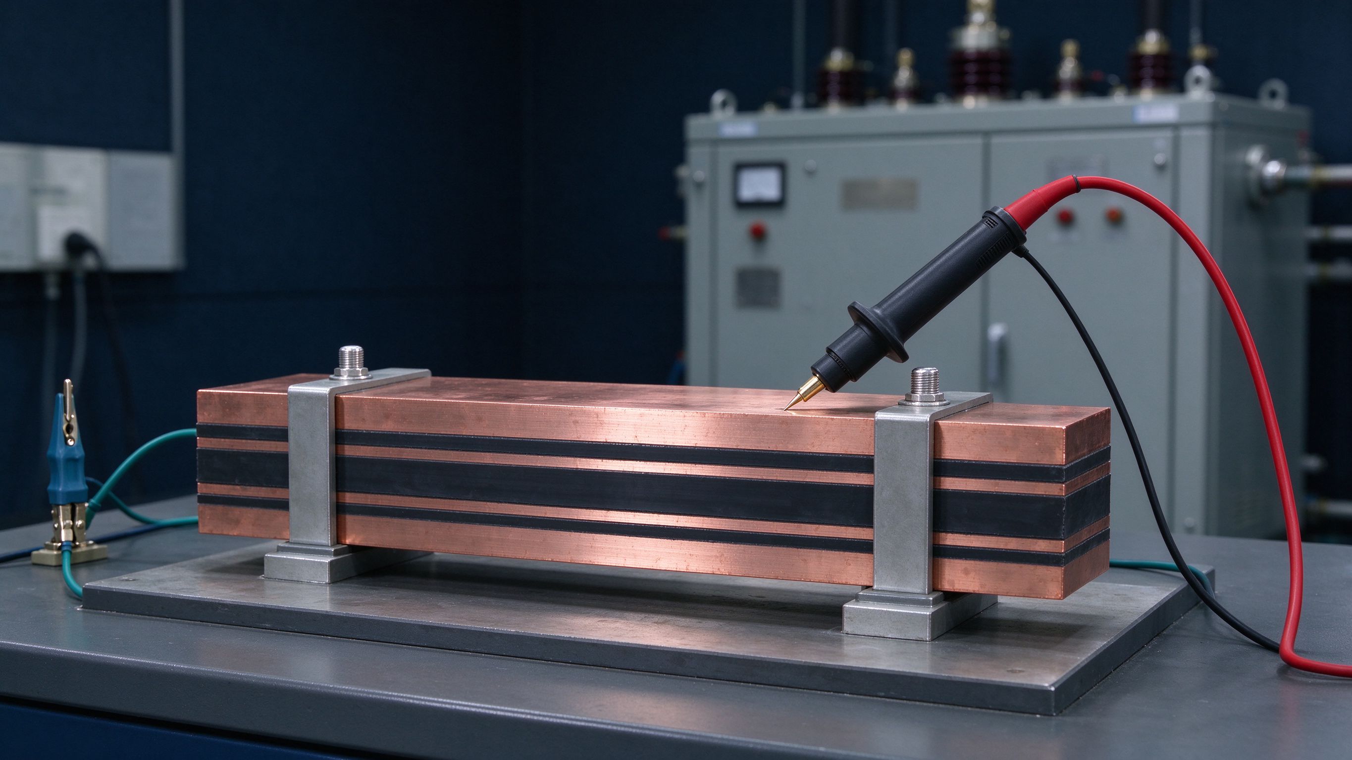
Insulation testing answers four questions: does it withstand rated voltage, does it discha
Read articleSend the current profile, voltage class and terminal types — our engineers reply within one business day.
Send drawings, current ratings and voltage class — DFM feedback and a quotation within one business day.
