Grid-scale battery energy storage (BESS) has moved from pilot projects to gigawatt-hour deployment. IRENA and BloombergNEF both project continued double-digit annual growth in installed storage capacity through 2030. Inside every project, the interconnect between battery racks, BMS, PCS, and auxiliary loads is quietly becoming the bottleneck. In this piece, the engineering team at SHANYUAN looks at how the energy storage busbar is evolving from a rack-level part into a site-level system, and what OEMs should plan for when they scale from a single cabinet to a GWh park.
Grid-scale battery energy storage (BESS) has moved from pilot projects to gigawatt-hour deployment. IRENA and BloombergNEF both project continued double-digit annual growth in installed storage capacity through 2030. Inside every project, the interconnect between battery racks, BMS, PCS, and auxiliary loads is quietly becoming the bottleneck. In this piece, the engineering team at SHANYUAN looks at how the energy storage busbar is evolving from a rack-level part into a site-level system, and what OEMs should plan for when they scale from a single cabinet to a GWh park.
A modern utility-scale BESS container holds a few dozen battery modules arranged in parallel strings, with a main DC bus running the length of the cabinet. At rack scale, the design is familiar: a single laminated busbar distributes current from the module fusion points to the main DC terminals, with fuses and contactors tapped off along the way.
At a GWh site, though, the architecture repeats. A 100 MWh project might consist of 20-40 containers, each with its own rack busbar, all paralleled into a site-level DC or AC collection bus. The problem is not any single rack; it is the interaction between racks. Cable trays and heavy flexibles between containers become unmanageable, contact resistance accumulates at every bolted joint, and fault energy can propagate across the site.
The market context matters. IRENA's Renewable Capacity Statistics and BloombergNEF's long-term storage outlook both point to multi-year growth in grid-scale BESS, driven by renewable integration, grid services, and capacity markets. TrendForce has similarly tracked the shift from small C&I storage to multi-hundred-MWh utility projects. For a power electronics busbar supplier, this means the ESS rack busbar is no longer a one-off design per container; it is a repeatable building block that must be designed once and deployed at scale.
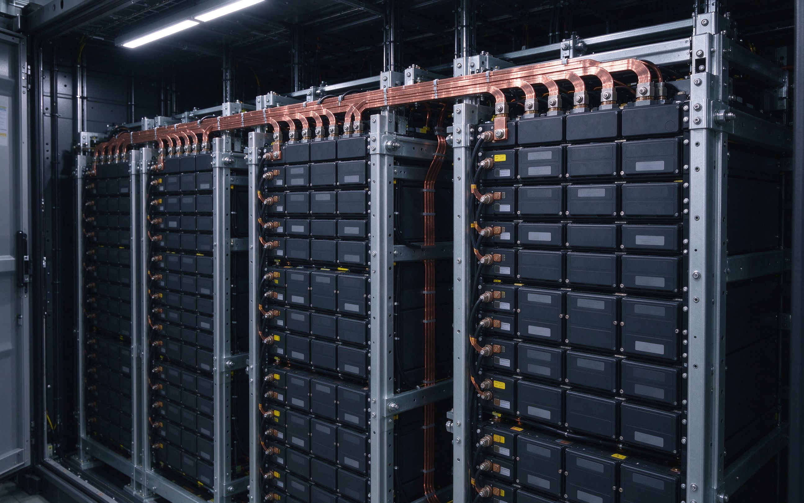
This is where an engineered laminated busbar approach extends naturally from the rack to the container and, increasingly, to the skid. Our ESS application page walks through the typical building blocks.
Single-container BESS used to top out around 1-1.5 MW of DC power. By 2026, 5 MW and 10 MW containers are on the roadmap from several integrators. DC voltages have crept from 750V to 1000V and 1500V class systems. At these levels, the main bus inside a cabinet carries continuous currents in the 800-1200 A range, with short-duration fault currents many times higher.
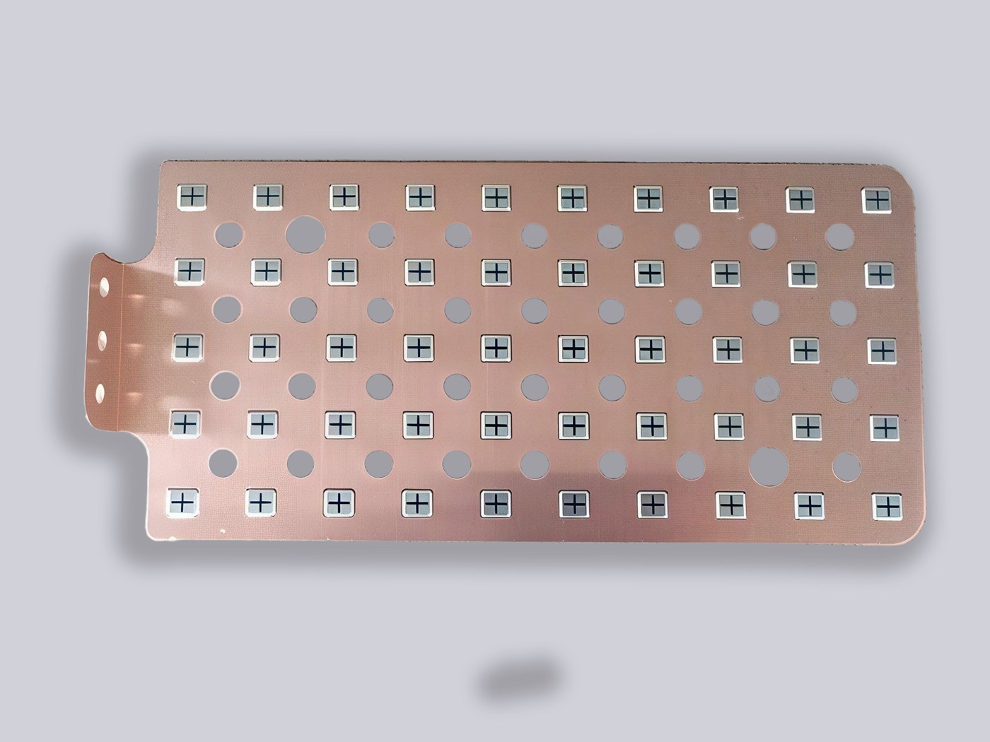
Flexible braided cables that were fine at 400 A become bulky, labor-intensive, and hard to torque consistently. A laminated busbar, by contrast, fixes geometry once: the C11000 copper layers are stamped, laser-cut, stacked with PET or Nomex dielectric, and vacuum-laminated. Every joint lands where the designer intended, and the contact resistance is repeatable unit after unit. For a broader comparison, see our note on busbar vs cable.
| Parameter | Flexible Cables | Laminated Busbar |
|---|---|---|
| Typical continuous current | Up to ~600 A per bundle | Up to ~1000 A per stack |
| Assembly labor per cabinet | High, manual routing | Low, drop-in part |
| Repeatability of contact resistance | Torque-dependent, drift risk | Controlled, tested |
| Inductance in switching loops | High, geometry varies | Low, interleaved layers |
| Weight for same current | Heavier | Lighter, compact |
| Spare parts SKU count | Many lengths and terminals | One drop-in part per cabinet |
The labor argument is often as strong as the electrical one. A cabinet builder wiring a busbar drop-in part spends minutes on the main bus; wiring a cable bundle spends hours. At hundreds of containers per project, the labor saving alone pays for the engineering effort upfront.
As BESS voltages climb toward 1500 V DC, dielectric selection moves from a line item to a reliability decision. PET film, which dominates cost-sensitive 400V EV and low-voltage storage packs, starts to look marginal. Nomex aramid paper, with its better thermal and partial-discharge behavior, is increasingly specified for the main bus in 1000V and 1500V containers. Epoxy powder (DLF) coating is used where complex shapes need full edge coverage.
Across the stack, SHANYU applies a full edge seal so that dust, humidity, and condensation cannot track across the cut edges. Every production unit receives a hipot test, an insulation-resistance check, and a continuity test before it ships. The 30°C ambient reference in our ampacity chart is the starting point; BESS cabinets that are forced-air cooled should be derated with the integrator's thermal model.
Design note: at 1500 V DC class, plan for reinforced insulation between adjacent layers, not just basic insulation. It is cheaper to specify this at DFM stage than to rework a stack after first article.
Creepage distances are also a function of pollution degree. A container sitting in a dusty, humid climate tracks faster than one in a climate-controlled room. We recommend designing to the harshest expected environment rather than the nominal one, because the busbar inside a sealed container still sees condensation on cold nights and dust on service days. For a deeper dive on material selection, see our busbar dielectric selection guide.
GWh projects are built by paralleling hundreds of rack strings. Two engineering problems follow. First, current sharing between parallel strings must be balanced; unequal sharing ages some modules faster than others. Second, fault energy from a single internal short must be contained locally without propagating across the site.
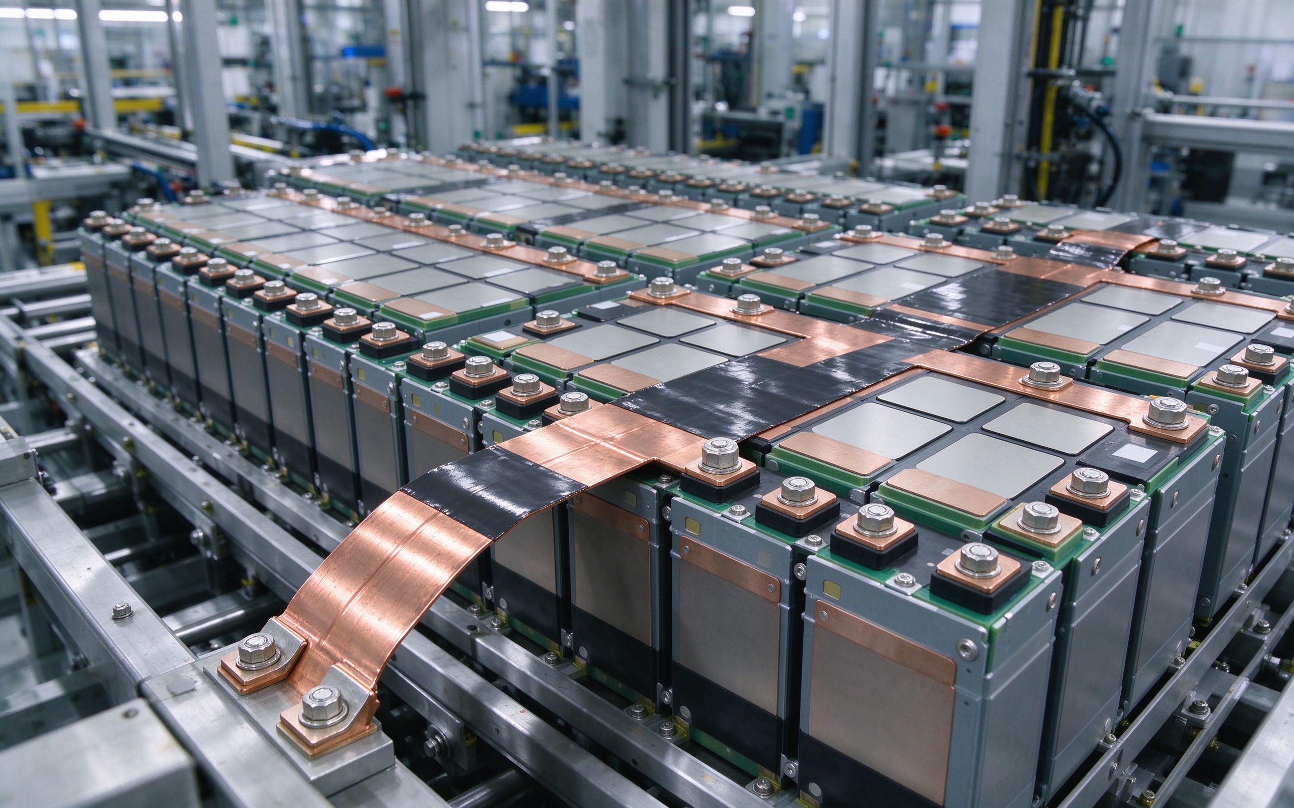
The busbar geometry contributes directly to both. A symmetric laminate, with matched trace widths and equal path lengths to each fuse tap, helps current sharing. Positioning fuses and contactors directly on the busbar (with bolted terminal interfaces) reduces the loop impedance that a fault sees, so protective devices clear faster. For inverter-side considerations, cross-read our article on SiC/IGBT DC-link busbar design; many of the same low-inductance principles apply to the PCS DC link.
Fuse coordination is a system-level exercise. The rack fuse, the container main fuse, and the site-level breaker have to coordinate so that the smallest fault upstream clears first without opening the main breaker. The busbar's impedance between those devices is part of the coordination calculation. A good DFM review flags where the busbar geometry changes the available fault current and lets the protection engineer size fuses correctly. It also flags where the busbar's own impedance can unbalance parallel strings: if the path from string A to the main bus is 20% longer than from string B, string A sees higher impedance and lower current, and its cells age differently. Designing symmetric trace lengths into the laminate costs nothing in copper but pays back in even aging across the pack.
Thermal consideration is the other half of the story. A GWh park sits in all weather, from desert heat to winter freeze. The busbar inside the cabinet sees both the external ambient and the heat from the modules. Our standard ampacity reference uses a 30°C ambient; for a cabinet in a 45°C summer climate, derating is essential. We recommend sizing the busbar for the worst-case cabinet internal temperature, not the outdoor nominal, because forced-air cooling inside a sealed cabinet rarely keeps up on a hot day.
Serviceability is the last design point that gets overlooked. A GWh park has a 20- to 30-year operating life, and at some point a cabinet needs to come offline for service. The rack busbar should be designed so that the cabinet can be isolated and serviced without unbolting the entire main bus. Pre-positioned service disconnects, labeled torque points, and accessible fuse taps all make the field technician's job shorter and safer. These are free to design in at DFM; they are expensive to retrofit in the field.
The bottom line for 2026: the energy storage busbar is no longer a rack afterthought. It is the part that connects the rack to the container, the container to the skid, and the skid to the grid. Design it once, repeat it across containers, and plan the supply chain like you would for any other long-lead electrical component. SHANYU is ready to support your next ESS program from DFM through mass production. Our Rizhao plant has run lamination, stamping, laser cutting, and 100% electrical test in-house since 2012, which means we can hold quality and lead-time commitments that depend on subcontractors cannot match. Send us your rack layout and current profile, and we will turn the first review around within one working day. We support projects from pilot racks through large multi-GWh utility-scale deployments worldwide.
A GWh project does not buy a busbar once. It buys thousands of identical parts across multiple production years. Two procurement behaviors matter.
First, lock the dielectric and copper grade early. C11000 copper is standard; aluminum is optional on select lower-current layers. Nomex and high-temperature films have longer lead times than PET, so choosing them at DFM rather than at production kickoff protects the schedule. Second, tie material pricing to a transparent copper benchmark (LME or COMEX) rather than letting it float inside a fixed quote. This is especially relevant in a year where copper prices are moving; our companion piece on copper price and busbar supply lays out the purchasing playbook.
SHANYU has manufactured laminated busbars in-house since 2012 at our Rizhao, Shandong plant. We offer DFM review before quoting, a custom busbar quote within one working day, samples in 5-7 working days, and mass production in 2-3 weeks. We ship internationally by sea and air. If you are evaluating a new ESS container design, send us the rack layout and current profile; we will come back with a geometry recommendation and a fixed-price budget.
For multi-year GWh programs, we recommend a rolling forecast. Raw copper stock, dielectric film stock, and lamination capacity all take weeks to plan. A 12-month rolling forecast with monthly updates lets us hold capacity and raw-material buffer for your program, which is the difference between a smooth ramp and a fire drill at month six.
To make the first RFQ productive, we suggest including the following in the package you send to a busbar supplier:
When you are ready to buy laminated busbars at project scale, reach the SHANYU team through /contact/ or write to busbar@shanyo.com. We will turn the first review around within one working day. We also support urgent pilot programs with air-freighted samples and can work from a rough sketch if formal drawings are not yet frozen.
The shift from 400V to 800V vehicle architectures is rewriting the electrical layout insid
Read articleCopper busbar current rating is not a single number. It is a starting ampacity adjusted by
Read article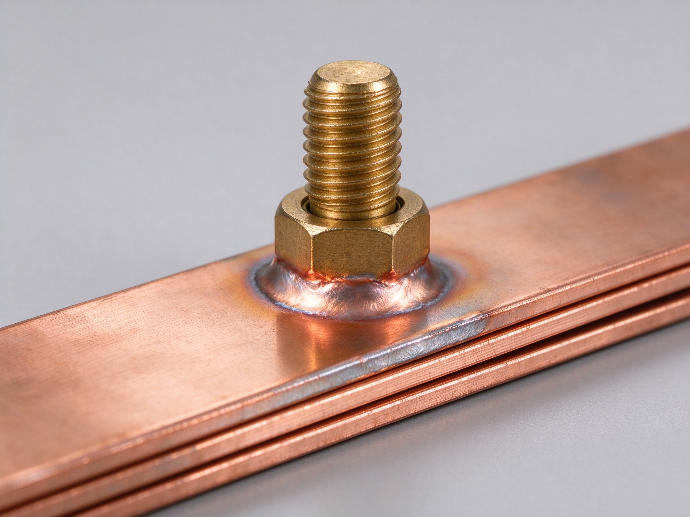
The terminal is where a laminated busbar meets the outside world. This guide covers M6/M8
Read articleSend the current profile, voltage class and terminal types — our engineers reply within one business day.
Send drawings, current ratings and voltage class — DFM feedback and a quotation within one business day.
