Every power-dense product eventually asks the same question: should this connection be a busbar or a cable harness? The answer is rarely either/or across a whole system — modern inverters, battery packs and data centers mix both. But the engineering logic is stable: at high current, a flat busbar carries more amps per cross-section than a round cable, its interleaved planes cancel magnetic field and cut stray inductance by an order of magnitude, it doubles as a capacitor and an EMI filter, and it occupies a fraction of the volume. Cables remain unbeatable for flexibility, serviceability and short low-current runs. This article gives the comparison numbers and a decision matrix you can apply to your own layout.
Every power-dense product eventually asks the same question: should this connection be a busbar or a cable harness? The answer is rarely either/or across a whole system — modern inverters, battery packs and data centers mix both. But the engineering logic is stable: at high current, a flat busbar carries more amps per cross-section than a round cable, its interleaved planes cancel magnetic field and cut stray inductance by an order of magnitude, it doubles as a capacitor and an EMI filter, and it occupies a fraction of the volume. Cables remain unbeatable for flexibility, serviceability and short low-current runs. This article gives the comparison numbers and a decision matrix you can apply to your own layout.
The first filter is current. A cable harness carries current through circular conductors, and circular cross-sections use their material poorly at high frequency and high current: skin effect pushes current to the outer surface, and the round geometry maximizes material for a given surface. A flat busbar presents more surface per cross-section, spreads current evenly, and couples conductors so their fields cancel. Practical numbers: a busbar carries more current than a round cable of the same cross-section — suppliers working at 48V/400V/800V architectures state it plainly — and the gap widens as current rises. If your connection carries tens to hundreds of amps continuously, the busbar conversation is worth having before the cable design is frozen. The electrical busbar range covers exactly this territory.
At inverter switching frequencies, parasitic inductance is not a footnote — it is the voltage-spike budget. A conventional harness has high, layout-dependent inductance, and every amp of switched current times that inductance produces a voltage spike that stresses the switching devices. Laminated busbars, with positive and negative planes interleaved and currents flowing in opposite directions, cancel their fields and deliver ultra-low inductance — measurements and simulation routinely show an order-of-magnitude reduction versus wiring. That is why SiC and IGBT inverter DC-link busbars are built laminated, not cabled. When comparing options, ask for the loop-inductance number at your switching frequency; if the supplier cannot give one, the comparison is incomplete. The low-inductance design resource explains the physics.
The comparison also depends on the connector ecosystem. A busbar terminates in a fixed pad, a bolted joint or a welded tab — each with a defined torque or weld schedule and a predictable resistance. A cable terminates in a lug, a ring terminal or a connector, and the connector interface is often the weakest thermal and electrical point in the whole path: a 200A cable through a mid-range connector can derate to 60% of the wire rating at the interface. When engineers compare busbar versus cable, they should compare the complete path — conductor, termination, connector — not the conductor alone. The connection design guidance lists the termination options with their resistance and torque values, which makes the comparison concrete instead of anecdotal.
Interleaved conductor planes separated by a thin dielectric form a distributed capacitor — a busbar quietly filters noise the way a discrete capacitor would. Harness wiring has negligible internal capacitance and offers no filtering, which pushes the EMI burden onto discrete components. In a dense inverter or converter this is a real bill of materials saving: the busbar's distributed capacitance absorbs switching transients at the point of use, reducing the discrete film-capacitor requirement at the module input. The trade-off is that the busbar's capacitance is fixed by geometry — you cannot tune it after layout — so the design has to be done right once. Engineers who treat the power-electronics busbar as a designed component, not a conductor, get the filter effect for free.
Geometry favors the busbar in every dimension. Analysis comparing a busbar with a round-wire bundle for the same duty has shown a busbar can require roughly one-tenth to one-half the space of a wire harness, with correspondingly lower weight. In a data-center rack, a traction inverter or a battery pack, that space saving translates into power density — the whole point of the products in question. The caveat: busbars are rigid and designed to a fixed layout, so the space saving comes with a commitment to that layout. Cable remains the escape hatch for late changes; a busbar is a frozen geometry. That is why the custom design route works the layout out early, before the fixture is committed.
One nuance engineers miss: the busbar's capacitance is distributed, not lumped, so its filtering action improves with area and worsens if the layout is stretched into thin long strips. A short, wide busbar between the DC-link caps and the switching stage behaves like a proper capacitor bank; a long thin bar between rack and drive adds little. The design consequence is that the busbar should sit as close to the switching stage as the mechanical layout allows — which is exactly how traction inverters are built, with the module landing directly on the laminated bus. The same placement rule applies in data-center power shelves and charging posts. When comparing busbar versus cable, the cable option always loses this bonus, because a harness has no useful internal capacitance regardless of where it runs.
The current-density comparison also has a number attached. A typical round cable derates with bundle size — ten cables in a bundle may carry only 60–70% of the single-cable rating because heat cannot escape from the middle of the bundle. A busbar derates far less, because its flat surfaces shed heat from both faces and the derating factors are driven by orientation, not packing. In a dense cabinet the practical effect is that the busbar carries its full computed rating while the cable bundle loses a third of its capacity. The ampacity calculator on this site applies the busbar side of that math with the 30 °C-rise criterion, and the comparison against a bundle derating curve makes the busbar look stronger the denser the enclosure gets.
Heat follows the same geometry as current. A flat busbar's large surface area rejects heat better than a round cable's; the flat planes can also be bonded to heat sinks or cold plates, making the bus itself a thermal path. Temperature-rise testing at high current consistently favors busbars, which is why high-power DC charging, traction and converter programs prefer flat aluminum or copper bars over shielded flexible cable — shielded cables in particular trap heat and derate hard. The thermal management guidance on this site quantifies the conduction paths. For a procurement or engineering comparison, the meaningful number is the temperature rise at your duty current in your cooling environment — not the conductor cross-section alone.

The space comparison is easiest to see in a rack: a row of high-current connections that takes a 300mm cable tray holds in a 50mm busbar shelf, with the conductors lying flat against the structure and doubling as mounting points for the modules above them. The mechanical side effects are positive too — a busbar stiffens the shelf, provides defined ground points, and removes the cable-routing inspection item from the assembly line. These are the properties that pushed data-center and storage manufacturers to laminated construction at 400V and now 800V, and the same geometry arguments hold inside any dense power product.
EMC is where the two technologies diverge most. A harness at high current radiates from its loops; controlling it means shielding, ferrites, routing discipline and often shielded cable, which adds cost and derates current. A laminated busbar cancels its own field — the opposing current planes create near-zero external field — and its internal capacitance filters differential noise. The result is that busbar-based designs pass radiated-emissions testing with far less countermeasure content. The comparison from converter practice is consistent: busbars improve EMC performance while reducing the discrete filtering bill. This is the quiet reason behind the power distribution design choices in modern inverters, and it is worth stating in any engineering review comparing a bus against a harness.
The thermal advantage compounds with integration: because the busbar is a flat, structural part, it can be clamped to a cold plate or bonded to a heat sink, turning the conductor itself into part of the cooling path. Cables cannot do this — their round form and jacket insulation trap heat, and the only cooling option is airflow around the bundle. In liquid-cooled systems, the busbar-to-cold-plate interface is a proven design pattern: the same surface that carries current conducts heat, so the thermal budget and the electrical budget are solved by the same component. The industrial application pages at SHANYUAN show this integrated construction in practice, and the thermal design notes give the conduction math for sizing the interface.
Busbars win the assembly argument in production: a laminated busbar is a plug-and-play part with zero mis-wiring risk — the conductor paths are fixed in the laminate, so the assembly error class disappears. Harness assembly carries mis-wiring, routing and tie-down risk, and the harness must be built and routed correctly every time. But cables win the service argument: a cable can be rerouted, replaced and repaired in the field; a busbar is a designed part that requires a replacement part if it fails. For products that ship in volume and never get opened, busbar is the production winner. For field-service-heavy installations where the layout changes, cable keeps the flexibility. The manufacturing process behind laminated construction is what makes the plug-and-play reliability possible.
One EMC detail worth stating: the benefit is structural, not adjustable. With a harness, you can move a cable, add a ferrite, or change the shield termination to fix a specific emission peak — each fix is a cost and a schedule line. With a busbar, the field cancellation is built in, so the emission floor is low by design and the remaining work is routing discipline and connector placement. The trade-off is the inverse: a busbar layout that is wrong is expensive to change, while a cable route can be moved in minutes. That is why busbar-based designs do their EMC thinking in the layout phase — plane gaps, slot openings, connector placement — rather than the test phase. The power distribution design notes describe the layout rules that keep the busbar advantage intact.
On a pure per-meter basis at low current, cable wins — it is a commodity with global supply. At high current and volume, the busbar wins the system cost: fewer parts, no shielding, no ferrites, less assembly labor, smaller enclosure. Tooling is the up-front difference — busbars carry design and tooling cost that amortizes over volume, while harnesses are cheap to start and expensive per unit in labor. The honest system view: a high-volume product with fixed layout saves money with busbars; a low-volume product with changing layout saves money with cables. Comparing quotes therefore requires the same data package for both — the busbar versus cable analysis on this site lays out the cost drivers in detail. Ask suppliers to quote the same duty on both architectures and the decision gets easy.
Standards add a filter. UL and IEC treatment of busbars and cables differs, and a product targeting a specific certification should check which distribution method the standard assumes: some standards evaluate the conductor path inside the equipment as a component, others as part of the enclosure. In practice, laminated busbars with documented dielectric and withstand testing satisfy the component-level evaluation cleanly, and the flat, insulated construction simplifies spacing and creepage arguments versus a bundle of round cables. The quality and testing evidence a supplier keeps — withstand, PD, thermal records — is exactly the file a certification engineer wants to see. For a product team, the choice of distribution method is also a certification-strategy choice, worth making in the same meeting as the electrical layout.
Inverter or converter DC-link, fast switching, space-constrained → laminated busbar. Battery pack internal connections, high current, vibration → busbar, rigid or flexible by movement. Data-center rack power distribution → busbar (see the data-center application notes). Low-current auxiliary, control and sensor runs → cable. Field-service layout with frequent changes → cable or hybrid. Short high-current point-to-point run inside an enclosure → busbar. Long routed run through a vehicle or structure with multiple bends → cable or flexible busbar, depending on current. The general rule: busbar where current, switching speed and volume are high; cable where flexibility, retrofit and low current dominate.
The enclosure saving is worth stating in money: a harness occupies volume that must be enclosed, routed, supported and cooled; a busbar lies flat against the structure and often eliminates a whole routing layer. In a sealed enclosure — battery pack, inverter housing, charging cabinet — every cubic centimeter costs sealing, cooling and material, so the busbar's space advantage compounds the part-cost advantage. Conversely, in an open, low-density product like a test bench or a retrofit, the enclosure saving does not exist and cable is the rational choice. The matrix therefore depends on the enclosure, not just the current. State the enclosure and cooling assumptions in the RFQ, and the quotes will line up with reality; the custom design route handles the enclosure-specific engineering.
Real products rarely go all-one-way. The winning pattern is a hybrid: a laminated busbar backbone carries the high-current trunk — battery to inverter, inverter to connector — with cable branches for control, sensing and low-current auxiliaries. This gives the busbar's inductance, EMC and space advantages where they matter, and cable's flexibility where the current is small enough to afford it. In a traction inverter, the IGBT module connects to a laminated DC-link busbar while the gate drivers run on ribbon and twisted pairs. In a data-center rack, the 800V DC trunk is a busbar and the rack-internal low-voltage rails are cables. Designing the split consciously is what the design guide teaches, and it is where most of the practical savings live.
Before committing, request three measurements from any supplier or internal test: (1) temperature rise at your duty current in your cooling condition, for both the busbar and the cable option; (2) loop inductance at your switching frequency — an inductance bridge or a dV/dt test on a representative loop; (3) radiated EMI on a representative prototype if emissions are a program risk. Add thermal cycling and vibration for the moving applications. The quality evidence SHANYUAN records per lot — withstand, continuity, insulation resistance and dimensional inspection — is the documentation baseline any busbar source should match. If a supplier only gives you a cross-section and a price, the comparison is not done.
The hybrid pattern also extends to voltage levels. At 400V and below, the cable option stays competitive for moderate currents because connector and insulation costs are low; at 800V DC, the insulation and shielding demands push the balance hard toward busbars, which is why data-center power shelves and high-voltage charging posts standardize on laminated construction. For a 48V auxiliary rail, cable remains the obvious choice. The decision matrix should therefore include the voltage class as a column, not just the current: the same 200A at 48V and at 800V land on different sides of the busbar-vs-cable line. The data-center application pages and the design guide both carry the voltage-dependent logic into specific layouts.
Is a busbar always better than cable at high current? For current density, inductance, EMI and space — yes. For service flexibility, retrofit and very low current — cable remains better, which is why hybrid architectures dominate. How much inductance does a busbar save? Typically an order of magnitude versus a conventional harness at the same current path, because interleaved planes cancel the magnetic field. Can I retrofit a busbar into an existing cable layout? No — a busbar is a designed geometry. Retrofitting means a new layout; that is why the decision belongs early in the design cycle. Do busbars need shielding? Generally no; the field-cancelling construction is the shielding. That saves cost and derating versus shielded cable.
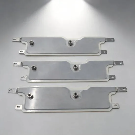
Voltage drop in a busbar decides whether the far end of a distribution system sees enough
Read article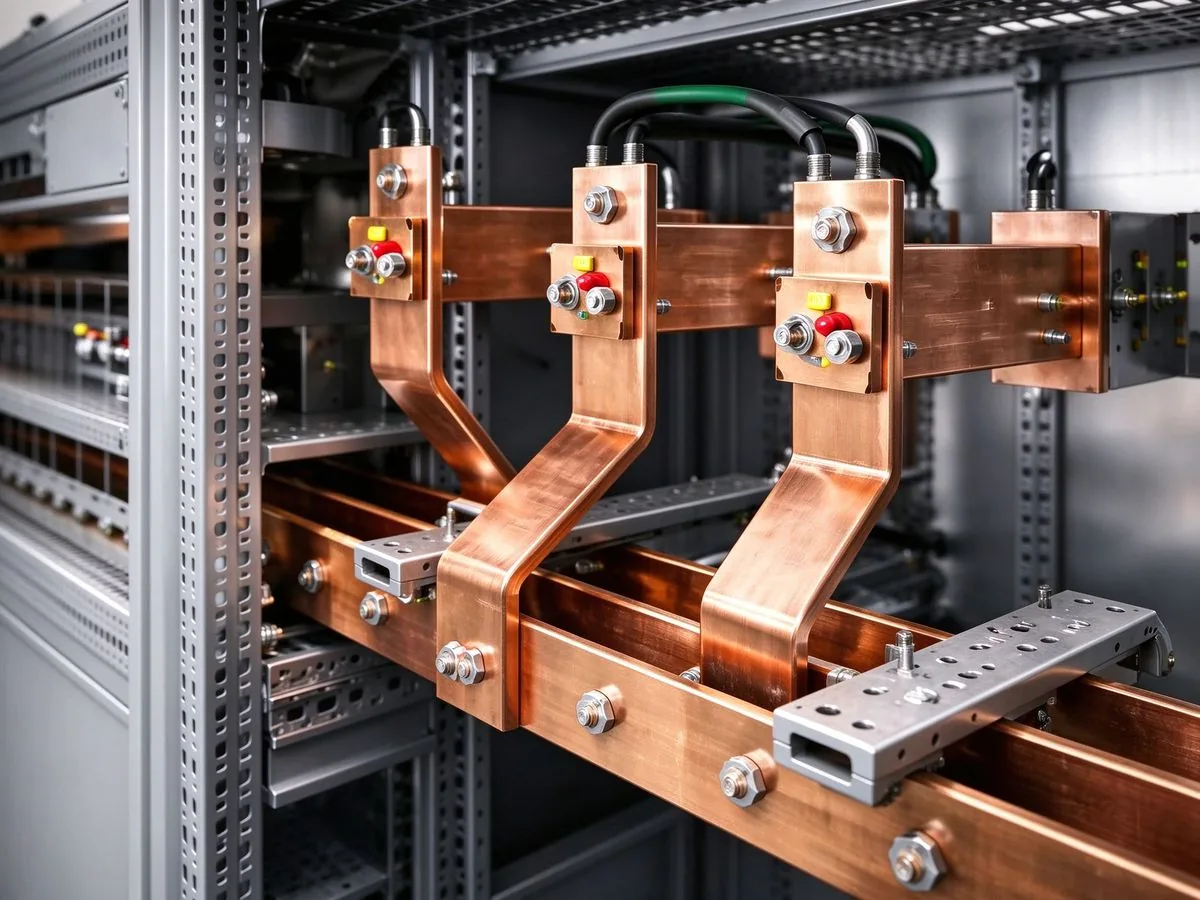
AI racks move from 140 kW to 1 MW by 2027, and the industry answers with 800 VDC distribut
Read article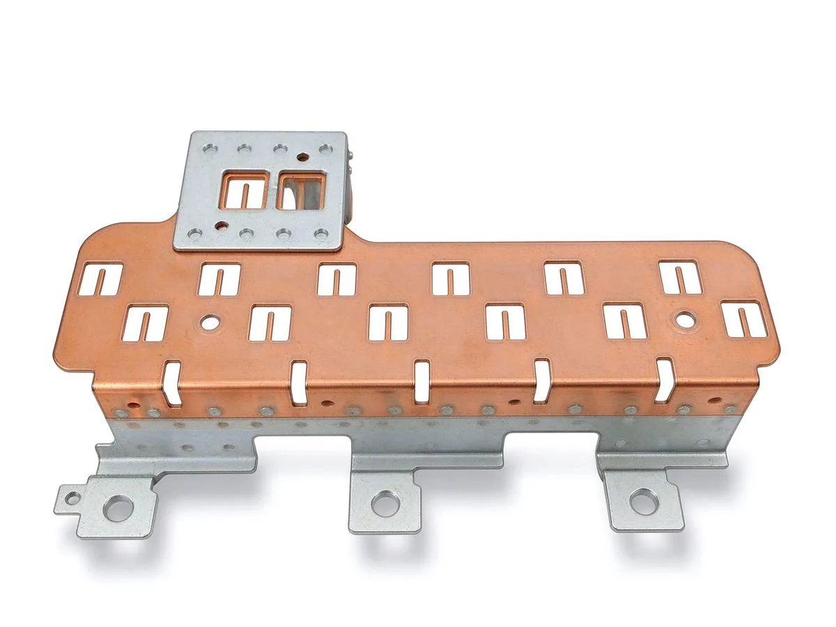
With type certification of the Valo moved to 2029 and the HECATE programme delivering 800V
Read article
David Osei is a product marketing engineer covering SHANYUAN's laminated busbar product lines. With 9 years in technical marketing for electrical components, he translates application requirements into product definitions, selection guides and technical content. He holds a B.Eng. in Electrical
Send the current profile, voltage class and terminal types — our engineers reply within one business day.