Wind power conversion in 2026 is moving in one direction: bigger turbines, stricter grid codes, more power electronics. Germany's offshore fleet crossed 10.8 GW for the first time in July 2026, and 15 MW-class machines are now specifying full-power converters at ratings their predecessors never needed. For a laminated busbar manufacturer, the nacelle DC link is where this trend becomes a drawing: higher loop currents, tighter space, vibration at 30 times per second, and salt air that attacks every interface. This article maps what the 15 MW era demands from the converter busbar and how suppliers should respond.
Wind power conversion in 2026 is moving in one direction: bigger turbines, stricter grid codes, more power electronics. Germany's offshore fleet crossed 10.8 GW for the first time in July 2026, and 15 MW-class machines are now specifying full-power converters at ratings their predecessors never needed. For a laminated busbar manufacturer, the nacelle DC link is where this trend becomes a drawing: higher loop currents, tighter space, vibration at 30 times per second, and salt air that attacks every interface. This article maps what the 15 MW era demands from the converter busbar and how suppliers should respond.
The Federal Association for Offshore Wind Energy confirmed in July 2026 that Germany's offshore wind capacity exceeded 10.8 GW for the first time. Behind that number is a fleet transition: repowering projects and new installations are deploying 15 MW-class turbines where 8 MW machines once stood, and each size step changes the power electronics. The nacelle converter for a 15 MW turbine must handle roughly twice the current of an 8 MW design at similar voltage, which pushes the DC-link busbar toward larger cross-sections and more parallel laminations.
The market picture supports the trend. Estimates for the wind power converter market range from US$6.8 billion in 2026 expanding to US$15.26 billion by 2035 at a 9.4% CAGR (Morgan Reed Insights, 2026), while other trackers put 2025 converter revenue at US$25.8 billion rising 9.1% to US$28.16 billion in 2026. Whatever the exact number, the direction is unambiguous: offshore build-out across Europe, Asia-Pacific and North America is the demand engine, and every turbine contains a power stack that a busbar manufacturer either supplies or misses.
At 15 MW, the machine-side and grid-side converters scale beyond what traditional medium-voltage stacks handle comfortably. Three architecture trends dominate 2026 designs. First, full-power converters (FPC) are now standard for the new class, replacing partial-load DFIG configurations for most offshore projects because grid codes require low-voltage ride-through and harmonic performance that only a fully rated converter delivers. Second, converter manufacturers are comparing medium-voltage (MV) and low-voltage (LV) full-converter approaches: Ingeteam presented a low-voltage full-converter concept for turbines above 10 MW in 2026, arguing for higher energy density and service-friendly packaging against the traditional MV-FC choice.
Third, wide-bandgap devices are moving into the nacelle. SiC-based converter topologies are being benchmarked against Si-IGBT three-level designs for next-generation turbines, with comparisons published in the 2025-2026 power electronics literature showing weight and loss advantages that matter in a nacelle. The consequence for the power electronics busbar is a low-inductance DC link that must hold its parasitic inductance down even as the loop currents grow.
The DC-link busbar couples the converter's DC bus to the IGBT or SiC power modules. In a 15 MW nacelle converter this bus carries thousands of amps at roughly 1,000-1,500V DC, and it does it in a volume measured in tens of litres. The engineering answer is a multi-layer laminated busbar: interleaved copper and dielectric layers that cancel the magnetic field between positive and negative planes, keeping loop inductance in the low nanohenry range.
Laminated construction also solves the second nacelle problem — space. A flat laminate replaces a bundle of cables and lugs, freeing volume for cooling and service access. Our impedance simulation work on wind converters typically targets loop inductance below 15 nH for the module interconnection section, which is achievable with mirrored layer stacks and tight terminal spacing.
A wind turbine nacelle vibrates continuously: blade-pass frequencies, gearbox harmonics and drive-train resonance excite the power stack at amplitudes a stationary converter never sees. Bolted busbar joints are the weak points — vibration relaxes clamp force, contact resistance rises, and a hot spot develops that infrared cameras find at the next inspection. The 2026 design response combines vibration-tested joint designs, torque-controlled fasteners with locking features, and busbar geometries that avoid cantilevered masses.
Our vibration and bolted joint design guide documents the testing approach: sinusoidal and random vibration profiles per IEC 60068-2-6 and IEC 60068-2-64, contact resistance measurement before and after, and re-torque verification. Offshore nacelles also add a 25-year fatigue expectation, which means every welded or bolted interface on the bus must be designed for cyclic loading, not just static current.
Offshore turbines run in a salt-laden atmosphere that attacks copper, plating and dielectric edges. The nacelle enclosure provides IP-rated protection, but service openings and thermal vents let humid salt air in, and condensation forms on cold metal after shutdown. The busbar's defence is layered: tin plating on connection surfaces, epoxy or powder coating where the bar is exposed, and creepage distances sized for polluted environments per IEC 60664-1 pollution degree 3.
Dielectric edges are the second corrosion entry point. A partial-discharge-free laminate keeps its insulation integrity only if the cut edges are clean and the layers fully bonded; salt ingress at a delaminated edge degrades into a PD site within seasons. Suppliers shipping into offshore programmes should include edge-sealing and salt-spray test evidence in the package — buyers are asking for it.
Offshore converters are tested at sea level but operate in humid, rapidly condensing air, and PD inception voltage drops as humidity climbs. A busbar that is PD-free at 1,200V RMS in a dry lab may start discharging at 800V in a fogged nacelle. The 2026 spec sheets reflect this: wind converter buyers request PD testing at elevated humidity and at the system's operating altitude, and they want the insulation test report to state the humidity at test time.
Design margin is the practical answer. Thicker dielectric, longer creepage and void-free lamination push the PD inception voltage well above the operating point so that humidity, temperature and ageing take years to bring it back down. Our partial discharge resource explains how inception voltage scales with laminate quality — the difference between a 1.2x and a 2x safety margin is mostly process, not material.
SiC MOSFETs switch faster than Si IGBTs, which lowers switching losses and shrinks filters — the weight story that matters in a nacelle. But faster switching raises di/dt, and every nanohenry of loop inductance becomes a larger overvoltage spike across the device. A SiC wind converter's DC-link busbar therefore needs an even tighter inductance budget than its IGBT predecessor, and the layout must place decoupling capacitors as close to the modules as the busbar geometry allows.
Published SiC module work is the reference: a 2025 IEEE design for a 10 kV SiC MOSFET module achieved 14.41 nH on its laminated busbar interconnection section and validated it with double-pulse testing, while FPC-integrated module concepts report ultralow parasitic inductance with balanced dynamic current sharing. For wind converters, the takeaway is that the SiC DC-link busbar is a co-design exercise with the power module, not an afterthought bolted on after the layout is fixed.
Far-offshore wind farms increasingly export through VSC-HVDC links, moving the conversion boundary from the AC collector to a converter station. The station's valve hall contains modular multilevel converters whose DC busbars run at 320 kV or higher — a different product class from the nacelle link, but the same physics: laminated, low-inductance, PD-free. Our HVDC converter station busbar article covers that side of the offshore supply chain.
For manufacturers, the two product families share process technology — lamination, plating, PD testing — but diverge in qualification depth. Station busbars carry single-point failure risk that nacelle links do not, so the test file is deeper and the documentation longer. Buyers who run both programmes tend to qualify one supplier on both, because the process discipline transfers.
Offshore collector networks are standardising on 66 kV AC, which pushes the transformer and switchgear side toward dry-type equipment that is lighter and easier to maintain offshore. The converter's grid-side connection into a 66 kV system raises the harmonics and cable-charging duty on the power stack, and the machine-side converter must tolerate the cable capacitance transients that a stiff onshore grid would mask.
The busbar consequence is on the AC side of the converter: phase busbars between converter output and transformer must carry high-frequency harmonic content, so skin and proximity effects stop being a laboratory topic and become a sizing input. A harmonic derating analysis per our harmonic current rating guide is now a routine request on wind converter RFQs.
Wind converter RFQs in 2026 should state the operating envelope with turbine-specific inputs: continuous RMS current at the DC link, peak switching current, voltage class, ambient inside the nacelle, vibration profile, humidity exposure, and the PD inception voltage required at operating conditions. A generic '5,000A laminated busbar' specification invites a generic result; the programmes that succeed define the transient duty and the environmental test regime up front.
The second RFQ element is the qualification plan. Nacelle busbars should be vibration-tested, salt-sprayed, and PD-measured before series release, with the reports attached to the sample-to-series gate. Our manufacturer selection guide lists the test evidence a credible supplier provides — and the questions to ask when the evidence is thin.
Offshore programmes run in series batches of hundreds of turbines, and every nacelle busbar should be traceable to its material lots and test records. Lot-level certificates, dimensional inspection data and PD reports per serial number are becoming contract requirements rather than extras. The manufacturing answer is a production line that treats each busbar as a serialised part — the same discipline our automated production line applies across the plant.
Traceability also protects the OEM: when a nacelle component shows a field anomaly, the ability to pull the busbar's full test file within hours decides whether the investigation takes days or months. Buyers should put data deliverable requirements — what reports, what format, what retention — into the contract, not discover the gap at the first audit.
The LV full-converter approach Ingeteam presented for >10 MW turbines targets energy density and serviceability: a low-voltage stack is modular, hoistable through the nacelle hatch, and serviceable at component level. That philosophy extends to the busbar: segmented laminates that bolt together in the nacelle beat one monolithic bar that requires a crane. The trade-off is more interfaces — and every interface is a potential hot spot and a corrosion entry.
Segmented design works when the joints are designed as joints: plated, torqued, documented, and positioned where service crews can reach them. Our busbar connection guidance covers the torque, plating and inspection regime that makes segmentation safe at offshore duty levels.
A 15 MW converter rejects megawatts of loss inside a nacelle that is, for cooling purposes, a sealed box. Liquid cooling is now standard on the power stack: cold plates carry heat from the IGBT/SiC modules to an external radiator loop, and the DC-link busbar sits on or beside those cold plates. The busbar's thermal design must therefore be co-developed with the cooling circuit — cross-sections sized for the loss density, interfaces located where the cold plate geometry allows, and dielectric rated for the plate temperature rather than the nacelle ambient.
The 30°C temperature-rise design rule that serves indoor busbars is not enough here. Nacelle hotspots form at the module interface, where the busbar lug meets the module terminal, and that interface is exactly where contact resistance and current density concentrate. Our thermal management resources cover the conduction path from terminal to cold plate, and the finite-element approach in our thermal design guide is the one we run on wind converter layouts before quoting.
The wind converter's fault duty is asymmetric: the machine-side converter feeds a generator that can deliver sustained fault current from rotating inertia, and the grid-side converter sees grid faults with a defined clearance time. The DC-link busbar must withstand both without exceeding its rated temperature rise or plastic deformation. Sizing therefore starts with the continuous current, then checks the peak fault current and its duration against the short-circuit withstand criteria — electromagnetic forces at thousands of amps can bend an unbraced bar before the protection operates.
Bracing and support spacing are part of the busbar drawing in wind programmes, not an installation detail. A laminated construction helps because the dielectric layer adds mechanical coupling between the positive and negative planes, but the support points still need to be designed for the peak force, and the assembly manual must specify the bracket torque. Buyers should ask for the fault-current calculation in the test file.
The machine-side converter's output connects to the generator through a bus that sees near-sinusoidal current but at high frequency and high RMS values. That interface is where terminal machining quality shows: hole position, pad flatness and plating thickness decide whether the joint holds its contact resistance for 25 years. Turbine OEMs in 2026 are tightening terminal inspection — CMM measurements on hole pitch, plating thickness verification, and torque documentation on every interface.
The second terminal concern is dissimilar-metal contact. Where the busbar meets transformer bushings or cable lugs of different plating, galvanic corrosion accelerates in the salt-laden nacelle. The design rule is to match plating systems and add a corrosion barrier where metals differ, a subject covered in our plating and corrosion guide. Mismatched interfaces are the most common field finding on offshore converter teardowns.
The wind industry's qualification discipline is closer to aviation than to industrial drives. A nacelle busbar moves through defined gates: design review with the converter OEM, prototype build with PD and vibration testing, first-article inspection, and a controlled series ramp with lot-level test records. Each gate has an approval document, and the quality system that supports those gates is what separates credible suppliers from quoting shops.
Our plant runs the same gates across power electronics busbar families, with the wind-specific tests — salt spray, random vibration, humidity cycling — executed in-house so the evidence lands with the quote rather than after it. OEMs who have been burned by cheap first articles increasingly require on-site witnessing of the PD test before series release.
Wind converter busbar cost breaks into metal, lamination, plating, machining and qualification. Copper dominates the material line and follows the LME market plus any tariff exposure — US-bound nacelle content now carries Section 232 considerations, which is why the tariff discussion appears in wind RFQs too. Qualification is the second cost centre: PD, vibration, salt-spray and fatigue test programmes add engineering hours that a commodity busbar shop never bills.
Buyers can control cost by batching: one qualified design across a turbine platform amortises the test programme over hundreds of units. Our sample-to-series page lays out how prototype-to-production pricing works when the qualification is shared — the same busbar gets cheaper per unit the moment the test programme is paid once, not per turbine.
The 15 MW era is not a 2027 problem; the first turbines are running and the converter supply chain is already re-specifying. Buyers should treat the nacelle DC-link busbar as a qualified safety component with a defined test file, not a machined copper blank with a drawing. The three questions that separate good from risky suppliers are simple: can you show PD evidence at operating humidity, can you document vibration and salt-spray qualification, and can you trace every series unit to its test records? If the answer to any is slow, the qualification risk is real.
For the industry, the direction is set: more SiC, more liquid cooling, more VSC-HVDC, more 66 kV collectors, and more power per nacelle. The renewable energy busbar conversation is becoming an engineering discipline of its own, and suppliers who invest in the test infrastructure are the ones who will be on the next tender list. Our inverter applications page tracks the same trends on the solar side.
Why do 15 MW turbines need a different DC-link busbar? Higher current at the same voltage means larger cross-sections, tighter inductance for SiC switching, and vibration/corrosion qualification that smaller turbines never required. Is aluminium viable in a nacelle? Rarely — the space and inductance budget favour copper, though hybrid sections appear on non-critical paths. What test file should the supplier provide? PD reports, vibration test results, salt-spray evidence, material certificates and lot traceability. How long does a wind converter busbar prototype take? With a complete RFQ, 2-4 weeks for the first article. Contact our engineering team with your converter layout for a feasibility review.
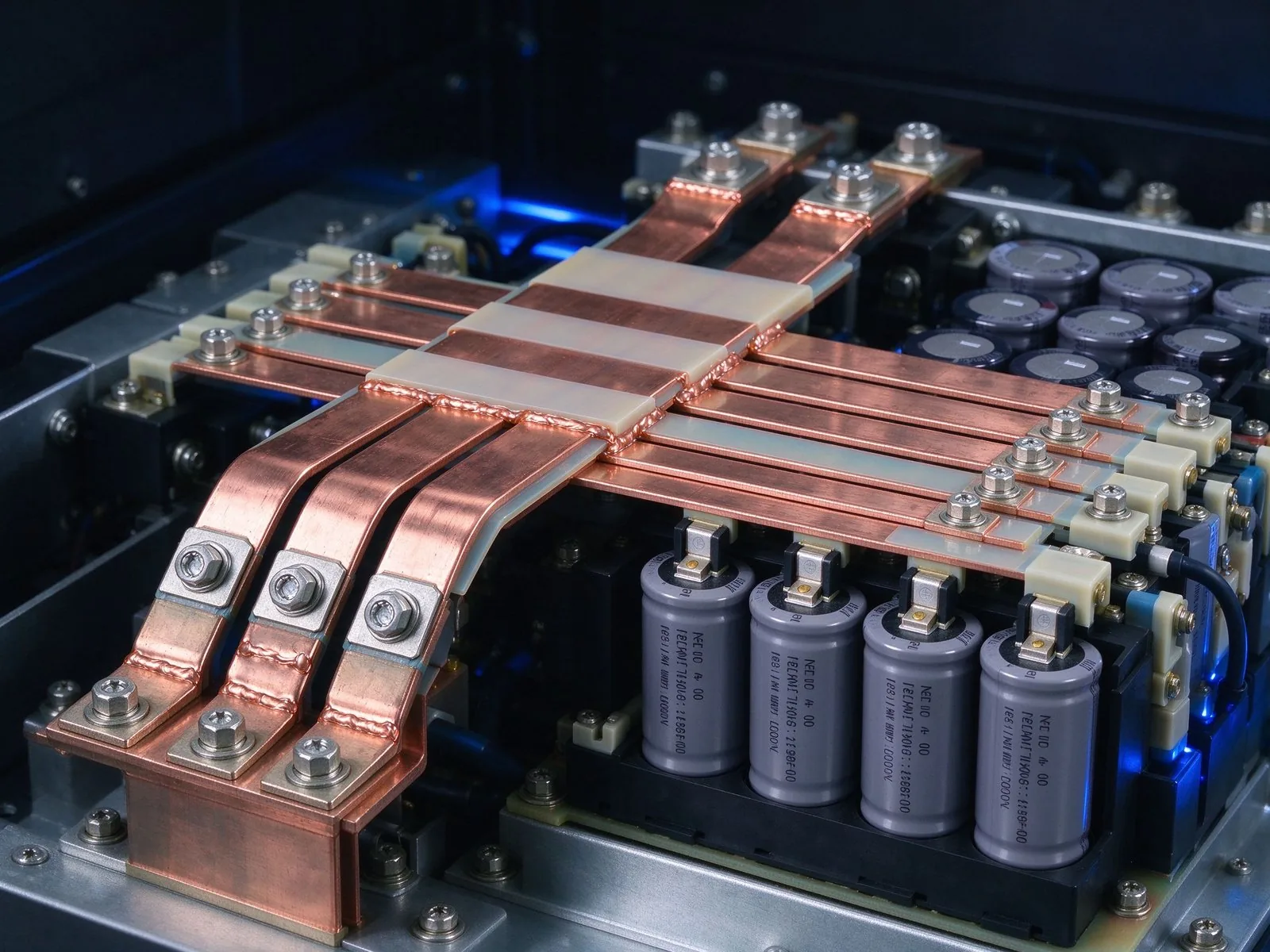
Germany's LanWin3/6, China's ±500 kV offshore VSC station and the CNY 4 trillion State Gri
Read article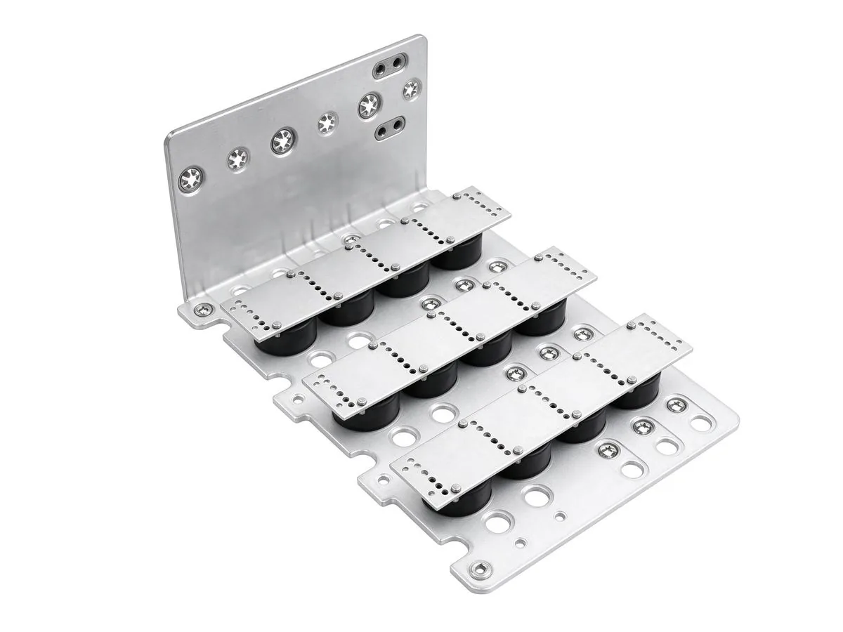
SiC traction converters grow from $0.33B to $0.61B by 2035, a 500 kVA full-SiC ANPC protot
Read article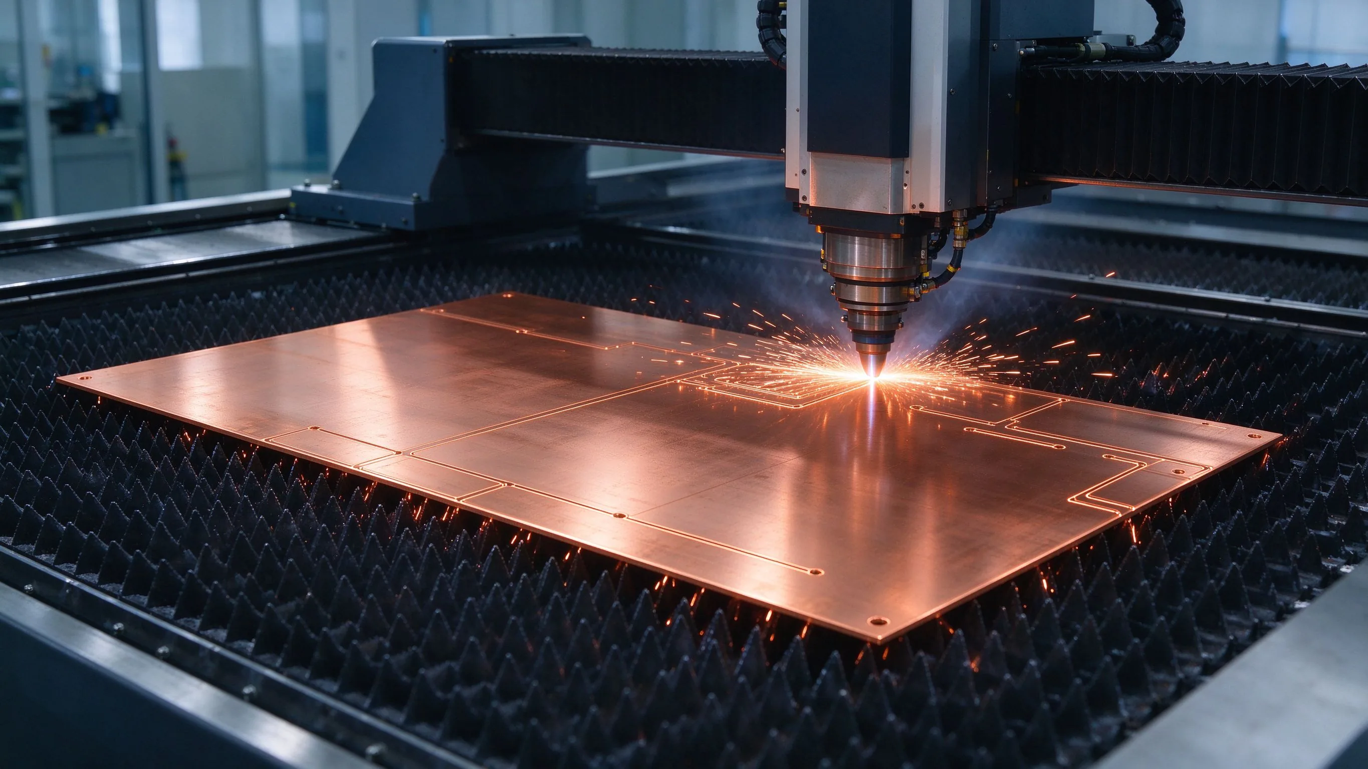
The April 2026 US Section 232 copper duties landed a 50%/25% tariff structure on busbar su
Read article
Elena Vasquez is a power electronics application engineer with 10 years of experience integrating laminated busbars into EV inverters, charging systems and energy-storage PCS. She specializes in low-inductance DC-link design, EMC behaviour and converter packaging, and holds a B.Sc. in Electrical Eng
Send the current profile, voltage class and terminal types — our engineers reply within one business day.