A plated surface on a copper busbar solves three problems at once: it protects the copper from oxidation and corrosion, it provides a low-resistance, solderable or weldable contact face, and it governs how the joint ages under vibration and temperature cycling. Yet many shop drawings still write only 'tinned' or 'silver plated', leaving the material grade, thickness, underlayer, measurement method and acceptance tests open to interpretation. This guide takes the manufacturing view of busbar electroplating: the process routes for tin, nickel and silver; how thickness should be selected and dimensioned; how plating affects contact resistance, voltage drop, soldering and welding; the adhesion, porosity and thickness tests that prove the finish; the RoHS and REACH constraints on restricted substances; and the callout language that should appear on a production drawing. It complements the corrosion-focused finish selection discussion with the process, tolerance and inspection detail a fabricator actually needs.
A plated surface on a copper busbar solves three problems at once: it protects the copper from oxidation and corrosion, it provides a low-resistance, solderable or weldable contact face, and it governs how the joint ages under vibration and temperature cycling. Yet many shop drawings still write only 'tinned' or 'silver plated', leaving the material grade, thickness, underlayer, measurement method and acceptance tests open to interpretation. This guide takes the manufacturing view of busbar electroplating: the process routes for tin, nickel and silver; how thickness should be selected and dimensioned; how plating affects contact resistance, voltage drop, soldering and welding; the adhesion, porosity and thickness tests that prove the finish; the RoHS and REACH constraints on restricted substances; and the callout language that should appear on a production drawing. It complements the corrosion-focused finish selection discussion with the process, tolerance and inspection detail a fabricator actually needs.
Bare copper oxidizes quickly in air: a thin oxide film forms on exposed faces, and in humid, sulfur-rich or salt-laden environments the surface darkens, thickens and becomes resistive. At a bolted joint, that oxide prevents intimate metal-to-metal contact, raises micro-ohms, generates heat at current flow and can creep under thermal cycling. Plating covers the copper with a layer that oxidizes slowly, forms a contact-friendly surface, and in the case of silver keeps its own oxide conductive. Plating also protects edges, holes and bend regions during handling and storage, prevents soldering contamination, and provides a consistent visual finish for inspection.
The choice between finishes is not cosmetic. Tin is the cost-effective default for indoor distribution and many power-electronics bars; nickel survives heat and aggressive atmospheres; silver minimizes joint resistance at high-current or separable contacts. Our companion note on corrosion-focused plating selection covers the environmental decision tree (salt spray, humidity, sulfur, outdoor exposure); this article concentrates on how each finish is produced, dimensioned, tested and declared. Where the two overlap, the corrosion guide chooses the material and this guide defines the process and the drawing requirement.
Two manufacturing realities frame the whole discussion. First, plating builds up on significant surfaces but thins in recesses, holes and inside bends because current density varies on the plating rack, so a single average thickness statement cannot control the finished part. Second, plating cost scales with plated surface area rather than copper mass: wide, thin bars spend proportionally more on the finish than thick narrow bars, which is why selective plating of only contact pads is common at volume. Both points belong in the RFQ and the production route sheet, not just the engineering specification.
Electroplating deposits a metallic layer from an electrolytic bath onto a cathodically connected workpiece. The typical sequence for a copper busbar is: mechanical cleaning and deburring; alkaline degreasing and acid pickling to remove oxide and scale; activation in a dilute acid strike; the strike or underlayer bath (often nickel); the main deposit (tin, nickel or silver); rinsing between stages; passivation or anti-tarnish treatment; drying; and final inspection. Good adhesion depends on a genuinely clean, oxide-free surface before the current starts; a part that reaches the plating line with stamping oil, fingerprints or oxide smut will delaminate later no matter how thick the deposit.
Substrate quality sets the baseline. SHANYUAN busbars use C11000 (electrolytic tough-pitch copper), which is roughly 99.9% Cu, soft and highly conductive, and it plates well when cleaned properly. Surface roughness from stamping, bending and machining affects finish appearance: smooth, prepared faces produce a uniform matte or bright deposit, while rough valleys retain solution and show thin spots. The laminated busbar manufacturing process overview shows where plating sits in the overall flow after stamping, bending and lamination, and fabrication tolerance guidance explains the dimensional calls that must be finalized before plating, because deposited thickness changes overall dimensions and fits.
Process control variables include bath chemistry and concentration, current density, temperature, pH, agitation, racking orientation and deposit time. Current density and time largely determine thickness; bath temperature and chemistry control grain structure, hardness and internal stress; racking position controls uniformity. A nickel barrier bath may precede tin or silver to suppress copper diffusion and intermetallic growth at elevated temperature, and that barrier itself must be specified and measured. Engineers involved in quoting should read the RFQ and supplier evaluation criteria to confirm the plating supplier's process control, certificates and inspection capability before volume release.
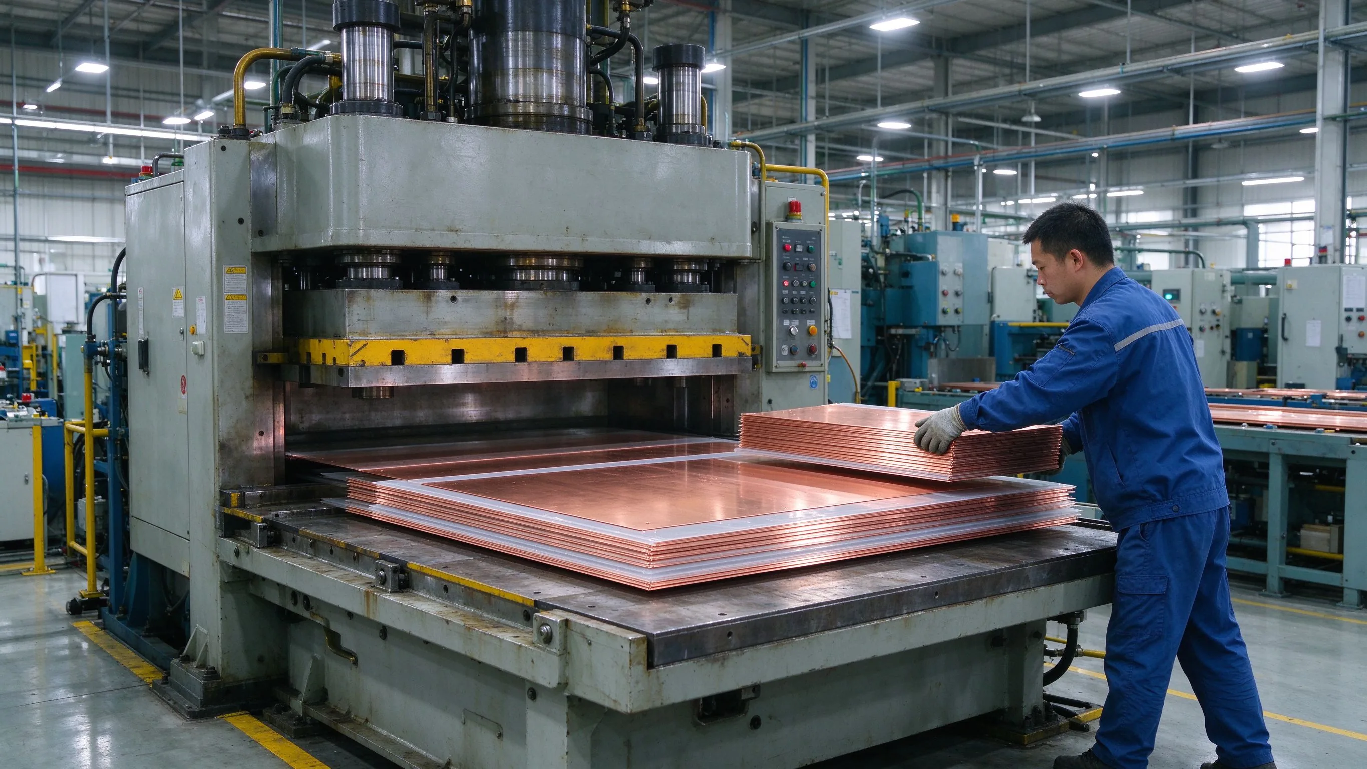
The overall manufacturing flow, including how plating sequences against film lamination and terminal joining, is described in the laminated busbar manufacturing process overview; finish quality depends as much on upstream cleanliness and geometry as on the plating bath itself.
Tin plating is the workhorse finish for busbars below roughly 120-130°C continuous service. Electroplated tin comes in bright (leveled, reflective) and matte (fine-grained, low stress) variants; hot-dip tinning is another route used on some heavier bars. Bright tin over copper can grow conductive whiskers under compression, so matte tin, reflowed tin, or tin over a nickel barrier are the standard mitigations, and the choice should be written on the drawing rather than assumed. Tin's low hardness means the coating deforms under bolt pressure, spreads into the surface valleys and creates a large true contact area, which is why even a modest tin film lowers joint resistance effectively in moderate environments.
Thickness follows service class. ASTM B545 defines service classes with minimum local thicknesses: Class A about 2.5µm for protected electronic contacts, Class B about 5µm for mild conditions and solderability, Class C about 8µm for moderate indoor exposure, Class D about 15µm for damp and mild industrial service, and Class E thicker for severe or hot exposure. Practical busbar practice for indoor switchgear and converter cabinets commonly lands at 8-12µm, increasing to 12-20µm in humid or coastal locations; below about 3µm pinholes can expose copper as high-resistance spots, while very thick soft tin creeps under sustained contact pressure and adds cost without benefit. The standard specifies local minimum thickness on significant surfaces, with mean thickness applied only when the purchaser explicitly requests it.
Tin excels where cost, solderability and low-temperature stability matter, and it pairs naturally with the welded or soldered terminal families described in welding and joining methods. It does not excel under sliding micro-motion, where fretting oxide powder accumulates, or above the intermetallic threshold, where Cu6Sn5 and Cu3Sn consume the free tin layer. Storage conditions also matter: tin finishes should be kept dry and packaged to prevent tarnish, and incoming inspection should check coverage on contact faces and tab ends before assembly. For terminal details, cross-reference terminal type selection and terminal connection design when deciding which faces carry the finish.
Nickel is the finish chosen when heat or chemistry rules tin out. Electrolytic nickel (ASTM B689) deposits under current and follows rack geometry; electroless nickel-phosphorus (ASTM B733, typically 5-12% P) deposits chemically without current, building a near-uniform thickness on edges, holes and bent faces where rack plating shows current-density variation. Nickel withstands continuous service around 250-300°C, resists salt fog, humidity, SO2 and H2S far better than tin, and at 200-700 HV depending on variant is hard enough to resist handling abrasion. It also serves as the standard diffusion barrier under silver for hot service and under tin where intermetallic growth must be suppressed above about 100°C.
Two cautions temper nickel's advantages. Nickel forms a tenacious passive oxide that requires adequate clamp force to break through at the joint, so contact resistance readings can be scattered if torque is uncontrolled; and nickel soldering needs an activated flux because wetting is less easy than on tin. In battery-module laser and ultrasonic welding, nickel-plated copper or nickel-coated foil became an industry standard because the finish tolerates the heat of fusion welding and does not flow like low-melting tin. Process engineers should review the welding and joining methods note when the finished bar enters a welded assembly, because finish choice and weld schedule must be qualified together.
Thickness strategy differs by role. A functional standalone nickel coating on a hot or corrosive bar runs roughly 8-15µm; a barrier underlayer under tin or silver needs only 2-5µm to block diffusion. Electroless Ni-P at 12-15µm is commonly specified for coastal substations, chemical plant busbars and outdoor enclosures. The environmental comparison with corrosion protection is extended in the plating corrosion guide, and the insulation side of a high-voltage bar, including film selection and processing order, belongs with surface insulation coating options, since plating and insulation are applied to complementary regions of the same part and must not interfere with one another.
Silver has the highest conductivity of any metal, about 105% IACS, and unlike tin and nickel its oxide remains electrically conductive, which keeps the joint contact resistance low and stable through thermal cycling. Silver is therefore specified for high-current disconnects, draw-out or plug-in contacts, busway joints, instrument-grade connections and locations where resistance directly limits the allowable temperature rise. Plain bare silver above roughly 150°C allows copper to diffuse upward and tarnish the finish from beneath, so silver over a 3-5µm nickel barrier extends reliable service into the 200°C+ range; sliding or separable contacts commonly receive 15-25µm because wear, not corrosion, governs life, while stationary bolted pads often use 8-12µm.
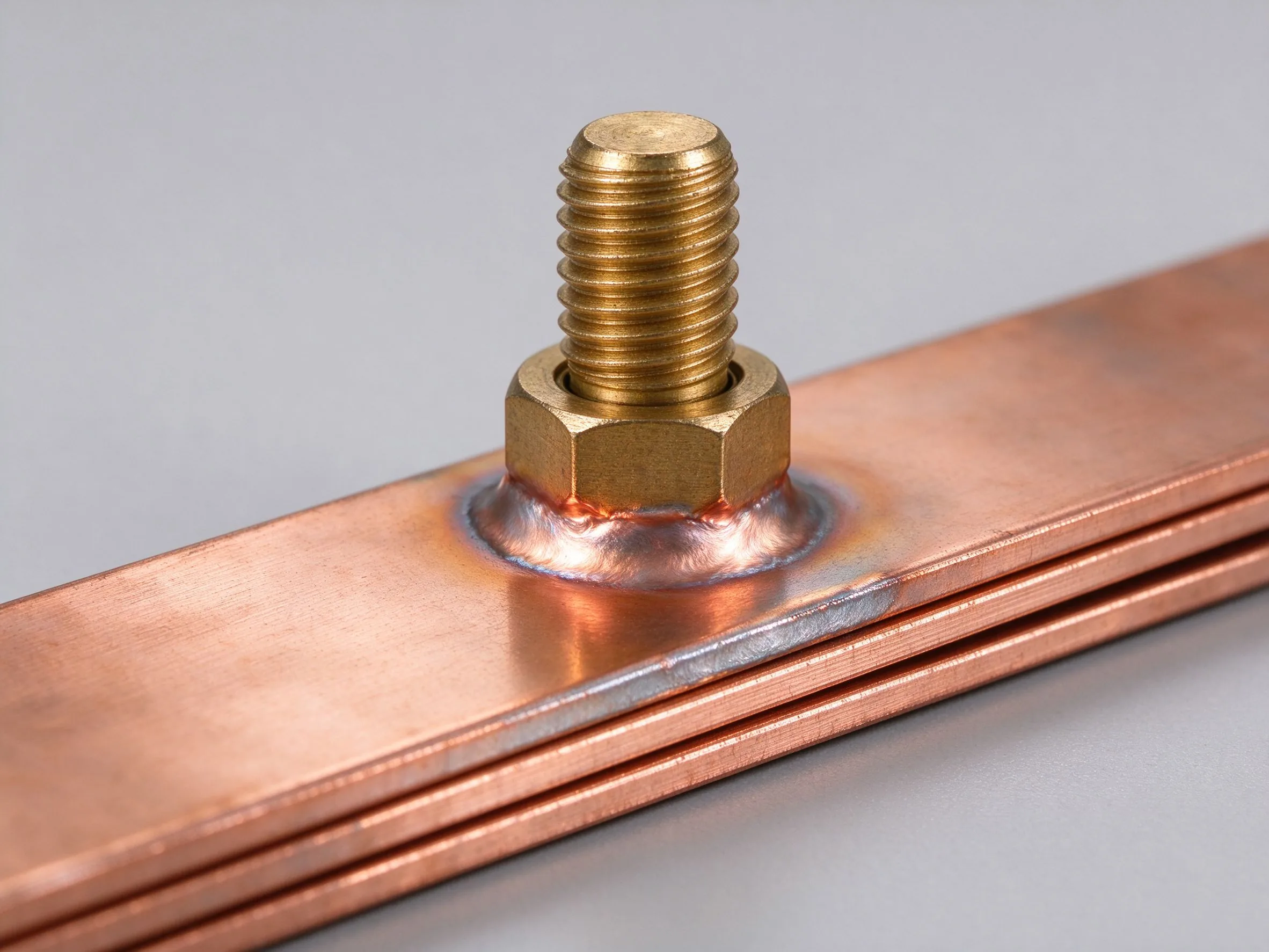
The cost is real: silver plating typically adds roughly 15-30% to the finished part price for 8-12µm over nickel, versus 3-6% for tin, and the charge tracks the silver spot price and the plated surface area. Selective plating is the standard mitigation: deposit silver only on the bolted contact pads and separators, leave the remainder tin-plated or bare where insulated, and mask or stop-off non-contact regions during the bath. Used well, selective plating removes a large share of silver cost with no measurable electrical penalty, but the masked boundaries must be clean, sealed and documented, and the spec must state pad outline dimensions, thickness and which faces are masked.
Silver tarnishes in sulfur-rich air, forming Ag2S that darkens the visual surface; anti-tarnish dip and nickel barrier mitigate appearance, though contact performance of tarnished silver remains far better than oxidized copper. For separable contacts, hard silver or silver alloy options improve wear, and galvanic compatibility between dissimilar plated finishes at a joint should be checked rather than assumed. Maintenance and disassembly practices after years of service are covered in maintenance and troubleshooting checks, which describe how to inspect joint resistance and refurbish plated pads during scheduled downtime.
The single most common specification error is writing a thickness without defining whether it is a local minimum or an arithmetic mean, and without identifying the significant surfaces where it applies. Standards such as ASTM B545 are built around minimum local thickness measured on the significant surface at any chosen spot; mean thickness applies only to small, simple parts when the purchaser explicitly calls for it. On a fabricated busbar with bends, holes and tabs, recessed corners and tube-like inner features naturally build less deposit than flat outer faces, so a mean value can hide thin spots at exactly the contact region where corrosion or diffusion starts.
Select thickness from the operating requirement upward rather than from habit. Define continuous temperature, atmosphere, joint type (bolted, welded, sliding, plug-in), expected service life and the maximum allowed micro-ohm after aging, then choose the finish and class: indoor moderate service 8-12µm tin; humid/outdoor tin 12-20µm; barrier nickel 2-5µm; functional nickel 8-15µm; stationary silver 8-12µm; sliding silver 15-25µm. Add manufacturing tolerances and inspection positions to the drawing, and distinguish the contact faces (where thickness matters electrically) from decorative or protected faces (where a lighter coating suffices). The fabrication tolerance guidance should be consulted alongside, because plating thickness adds to overall dimensions at mating holes and slots and can change fit-up with insulators and covers.
Document the measurement basis up front: which gauge or method, which reference standard, how many spots on each significant surface, and the acceptance lower limit. When a program uses selective plating, list the masked zones and deposit zones on a finish diagram, and note that mask removal must not leave adhesive residue that interferes with insulation film bonding. Early samples and quick-sample and prototyping workflow reviews are the right moment to lock thickness and layout, since changing a plating callout after production tooling and masks are prepared causes rework and delay.
Plating changes the resistance of the joint, not the resistance of the copper bar itself. The copper cross-section still dominates bulk resistance and voltage drop along the bar; the finish governs the constriction and film resistance at each interface between the bar and a lug, module, stud or mating connector. At a bolted joint, soft tin deforms and cold-flows under clamp pressure to expand real contact area, giving low and reproducible resistance at modest cost; silver combines a conductive oxide with softness for the lowest stable value; nickel stays hard and passive, so it needs higher force and shows wider scatter unless the oxide film is broken down.
Resistance stability over life matters more than the initial value. Tin joints that cycle in vibration can frett, silver joints remain stable but cost more, and nickel joints resist chemical attack. After thermal cycling, the joint should be re-measured against the pre-cycle baseline; a large upward drift signals intermetallic growth, fretting oxide or loosened torque. The terminal connection design note covers torque values, washer choices and contact-force requirements, and the voltage-drop and power-loss guide converts end-to-end resistance into heat. Temperature rise at the joint rises with the square of current times resistance, so a small plating-related resistance increase at a high-current pad can move the hotspot onto a component datasheet limit; finish verification should therefore be tied to the assembled-system temperature-rise test, not a standalone coupon.
Where plating thickness seems to affect ampacity, the mechanism is indirect: thicker soft tin slightly changes contact fit and creep, while surface emissivity and cleanliness influence radiative heat loss. The conductor sizing itself follows current, duty and cooling as explained in busbar current-capacity basics; the finish choice should be justified by interface performance, and any joint resistance allowance should enter the thermal model explicitly. Good engineering practice records initial micro-ohms, test torque, cycle history and final micro-ohms in the quality record that travels with the production lot.
Terminals on a busbar may be bolted, soldered, brazed, laser-welded or ultrasonically welded, and the finish interacts differently with each process. Tin plating supports soldering directly because tin matches solder chemistry and wets reliably; silver also solders well; nickel requires an activated or aggressive flux and forms a less forgiving wetting surface, while thick tin on a weld preparation can introduce porosity, spatter or inconsistent fusion because the low-melting layer vaporizes under the energy beam. For laser and ultrasonic welds to battery modules and capacitor terminals, nickel-plated copper surfaces became the established choice precisely because the finish survives welding heat and resists flow, whereas soft tin contributes weld contamination and mechanical softness at the fusion zone.
Process engineers must qualify the finish and the joining schedule together: plating thickness, cleanliness, oxide condition and surface roughness all change the energy input needed for a good weld, and a qualifying coupon set should cover the actual plating spec, the actual terminal geometry and the production clamp force. Joint strength, pull or peel tests, cross-section inspection and electrical resistance should be recorded. The welding and joining methods reference contrasts these routes and their inspection requirements, and terminal type selection links the chosen join method to the mechanical terminal design (stud, blade, tab or welded butt).
A practical rule is to specify finish zones by join method: solderable tabs get matte tin; high-heat welded interfaces get nickel; separable high-current pads get silver or silver-over-nickel; insulated zones stay bare or film-covered after masking. Drawing notes should state which faces must remain free of plating for welding, because plating over a weld land can be difficult and expensive to strip after the fact. Production flow should sequence operations so that plating, insulation film lamination, welding and final cleaning occur in an order that protects each interface, consistent with the manufacturing flow described in the laminated busbar manufacturing process overview.
Three independent quality properties define whether a plating job passes: adhesion (the layer stays bonded), porosity (no through-holes exposing substrate), and appearance (uniform color, no blisters, pits, scorch marks or contamination). Adhesion tests include bend or peel methods per standards such as ASTM B571: the sample is bent, twisted or impact-scribed, and the coating must not blister, flake or peel away from the substrate. Thermal-shock cycling can expose weak adhesion as blistering after expansion mismatch between copper and deposit. Porosity is assessed by a ferroxyl or spot chemical test that reveals exposed substrate spots by discoloration, supplemented by visual and microscopy inspection; high-porosity finishes fail corrosion aging even if the measured thickness looks adequate.
Corrosion acceptance commonly uses neutral salt spray per ASTM B117 or ISO 9227 for a defined number of hours, with the acceptance criterion stating that no base-metal corrosion appears on significant surfaces and that the finish remains functional after exposure. Electrical acceptance on finished parts measures joint contact resistance at the specified torque, before and after thermal cycling, referencing connector and contact test norms such as IEC 60512-style methods where applicable. Appearance criteria should define matte versus bright finish, allowed color variation, edge coverage and the treatment of non-significant surfaces, because 'looks good' without criteria leads to inconsistent shop acceptance. The broader electrical insulation validation on the assembled bar, including hipot and resistance checks, follows insulation testing procedures and should run after plating and film lamination are complete.
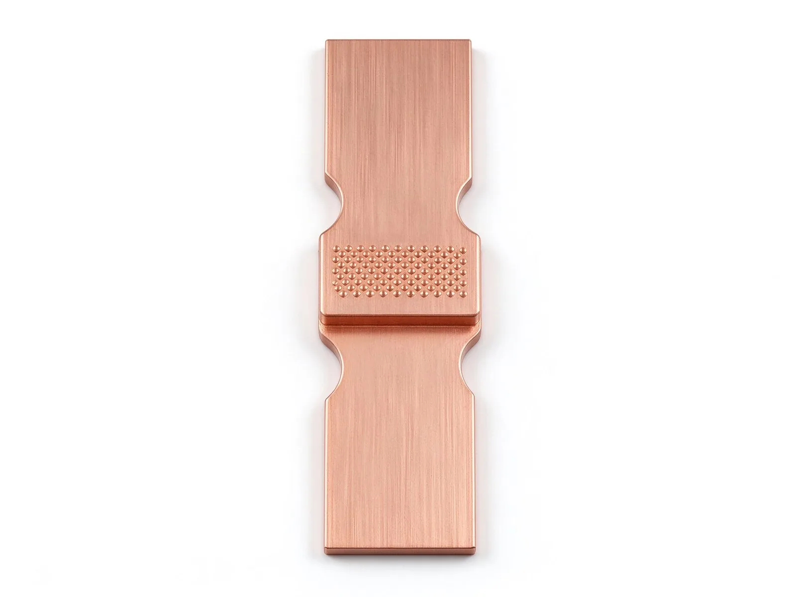
Failure modes worth targeting in inspection include: peeling or lifted edges after bending; pinholes clustered near drilled holes; blistering after bake or thermal shock; uneven buildup caused by poor racking; tarnish or discoloration from stale baths; and residual mask adhesive. Reference the catalog of common busbar failure modes when root-causing a rejected lot, and capture each test result against a numbered finish specification in the quality record. A consistent, written acceptance plan also protects buyers in audits: when the supplier ships certificates, they should map each certificate to the exact test, standard, sample lot and acceptance limit rather than presenting a generic 'RoHS compliant' statement.
Thickness cannot be verified by eye, and the choice of gauge depends on material system, production volume and accuracy need. X-ray fluorescence (XRF) is the primary non-destructive method for metallic coatings on metal substrates: it excites the deposit and substrate atoms and derives thickness from emitted fluorescence, supports multilayer analysis such as nickel-under-tin or silver-over-nickel, and achieves relative standard deviations below roughly 2-3% on calibrated instruments. It suits batch spot checks on contact pads, masks the selected spots on the part drawing, and leaves the part usable. Magnetic induction applies to non-magnetic coatings on ferromagnetic substrates; eddy current applies to non-conductive coatings on non-ferrous metal, and neither is a substitute for XRF on tin or silver over copper, where both deposit and substrate conduct and respond similarly.
Destructive arbitration methods remain necessary for process qualification and dispute resolution. The cross-section method cuts a representative sample, mounts it in resin, polishes and etches the layers, and measures deposit thickness under a microscope or SEM, revealing not only thickness but also adhesion gaps, pores and intermetallic layers. Coulombometric (anodic stripping) methods dissolve a defined circular area and derive thickness from charge; they are used in laboratories and plating-house control. Production-line gauges may combine inline XRF or beta backscatter with offline coupon checks, and shop records should state which method governs customer acceptance. More on method selection and uncertainty appears in the measurement-engineering literature summarized by fabrication tolerance guidance for the dimensional side of the finished bar.
Calibration and positioning are the practical accuracy drivers. XRF requires standards matched to the substrate and deposit composition; measuring on curved tabs or near edges introduces errors, so measurement locations should be flat representative areas away from holes and bends, with several spots averaged only where a mean requirement exists. Record the instrument, calibration date, spot coordinates and measured value on the inspection report. When silver plating carries material cost, suppliers monitor bath deposition and gauge trends continuously to avoid both under-plating that fails performance and over-plating that wastes expensive metal, balancing yield, quality and cost inside the production route defined alongside the DFM checklist for production release.
Busbars shipped into electrical and electronic equipment on the European market must comply with the RoHS Directive (2011/65/EU), which restricts ten substances in homogeneous materials: lead, mercury and hexavalent chromium limited to 0.1% by mass, cadmium to 0.01%, plus brominated flame retardants and selected phthalates. For plating shops this directly means choosing lead-free tin (modern matte tin alloys avoid the older tin-lead bright finishes), avoiding hexavalent chromium conversion coatings in favor of trivalent alternatives or no passivation where unnecessary, and controlling cadmium in any nickel or silver process chemistry. A Declaration of Conformity and traceable material data should accompany production lots, and the CE documentation chain for the finished equipment depends on the component-level declaration being available.
REACH (EC No. 1907/2006) adds a different, broader obligation: the Registration, Evaluation, Authorisation and Restriction framework keeps a growing Candidate List (SVHC) of substances of very high concern, and items placed on the market require disclosure when certain SVHC thresholds are exceeded, while certain substances require authorisation for specific uses. Legacy cyanide-based silver plating baths and chromic-acid processes sit in regulated or authorization-heavy territory; modern compliant lines increasingly use non-cyanide silver formulations and trivalent chemistry, and buyers should request the supplier's current REACH declaration and the latest SVHC update rather than relying on a static brochure. The commercial context of sourcing under tariffs and restricted materials, including supplier risk, is discussed in trade and tariff supply considerations, while the regulatory content of the larger EV and ESS ecosystem connects to EU battery regulation implications for busbars.
Practical compliance steps for a busbar program are straightforward: define the target markets and applicable directives in the RFQ; request material and finish declarations (lead-free tin, RoHS 10-substance statement, current REACH/SVHC declaration, non-Cr(VI) statement); keep certificates tied to lot numbers; retain bath SDS and change records; and avoid specifying banned finish chemistries in the drawing. Residual cleaning salts, passivates and packaging anti-tarnish oils should also be disclosed if they contain restricted substances, because compliance is evaluated at homogeneous-material level, not only at the plated metal itself. Quality teams should review declarations before production release, mirroring the document hygiene described in the supplier evaluation criteria note.
A complete finish callout names the deposit metal and type, the minimum local thickness on significant surfaces, any underlayer, the applicable standard, the acceptance tests and the inspection basis. A minimal high-quality note reads, for example: 'Tin plating per ASTM B545 Class C, matte tin, minimum 8µm local thickness on marked contact faces; 2-5µm nickel barrier where temperature exceeds 100°C; adhesion per ASTM B571; RoHS and REACH compliant; lead-free; XRF measured on inspection spots listed in the finish diagram.' A silver callout should read similarly: 'Silver 8-12µm over 3-5µm nickel on bolted pads only; masked elsewhere; sliding contacts 15-25µm; salt spray per ASTM B117 for the agreed hours; contact resistance measured at specified torque.' The exact words vary, but the elements must be complete.
Elements to include on the drawing or its accompanying finish sheet: deposit metal and grade (matte/bright tin; electroplated or electroless nickel-P and %P range; pure or hardened silver); thickness as local minimum with the unit (µm or micro-inches) and the reference class; underlayer metal and thickness; significant-surface identification via a finish diagram or numbered zones; measurement method (XRF spot locations, cross-section for approval lot); adhesion and corrosion test references and acceptance limits; solderability or weld-zone restrictions (which faces stay bare); compliance declarations (lead-free, RoHS, REACH/SVHC, no Cr(VI)); appearance standard (color, uniformity, allowed edge buildup); and packaging/tarnish protection for storage. The DFM checklist for production release should require this note before the part is routed to plating, and the fabrication tolerance guidance should cover allowable buildup at holes and slots.
Conversely, callouts to avoid: 'tinned' without thickness; 'silver plated' without underlayer or pad boundary; a thickness given as average only on a shaped part; no test method or acceptance criterion; plating specified on weld lands; compliance claimed without a document reference; and thickness tighter than the bath can repeat economically, which raises reject rates. When multiple finishes appear on one part, the finish diagram should dominate the note, using zone letters and arrows to each pad, because text alone on a complex laminated bar creates ambiguity during shop floor processing. Cross-link the drawing note to the terminal and insulation drawings so that plating zones, insulation film zones and weld lands do not overlap unintentionally, following the cross-functional layout logic in multi-layer laminated busbar selection.
Rizhao Shanyuan Electronic Components Co., Ltd. (SHANYUAN), founded in March 2012 and operating a 17,200 m² plant at Taoyuan Village, Wulian Street, Rizhao, Shandong, China, exports insulated laminated busbars to more than 20 countries. Standard products are built on C11000 copper in one to six-plus layers, rated up to roughly 1000A, with PET, Nomex or DLF insulation, a controlled 30°C temperature-rise design basis, tin-plated contact surfaces, and M6/M8 threaded studs, blade terminals and welded terminal arrangements. The standard manufacturing flow integrates stamping, forming, lamination, insulation application, terminal joining and finish processing, with thickness and dimensional controls aligned to customer drawing requirements and agreed standards.
For programs needing finish variation beyond standard tin, the RFQ documentation should state the required finish on each zone, thickness and class, any nickel underlayer or selective silver pad, the solder or weld condition of each terminal, compliance expectations (lead-free tin, RoHS, REACH/SVHC declaration, Cr(VI)-free), the qualification tests and pass criteria, and sample-lot measurement records. SHANYUAN's engineering team reviews drawings for manufacturability before quoting, covering bend feasibility, terminal design, insulation routing and finish sequence, and can coordinate samples and inspection reports before production release; supporting reference notes on this site include the manufacturing process flow, the tolerance guide, the joining methods guide and the prototyping workflow.
Buyers may send drawings, current and voltage data, environment and test requirements, and target volumes to busbar@shanyo.com for a technical quotation. Whether the part is a simple distribution bar, a laminated power-electronics stack or a custom welded assembly, the plating section of the RFQ should be treated as a controlled specification rather than a preference: metal grade, thickness, underlayer, test method and compliance documents protect joint reliability over the vehicle or equipment life and prevent disputes at incoming inspection. Combined with the corrosion guide for material selection, the process and inspection detail in this article gives both designers and fabricators a shared manufacturing vocabulary for reliable, compliant, cost-controlled busbar finishes.

The plating on a busbar contact is a corrosion strategy as much as a conductivity play. Ti
Read articleFrom C11000 copper coil to a fully sealed, tested multi-layer busbar, this walkthrough exp
Read article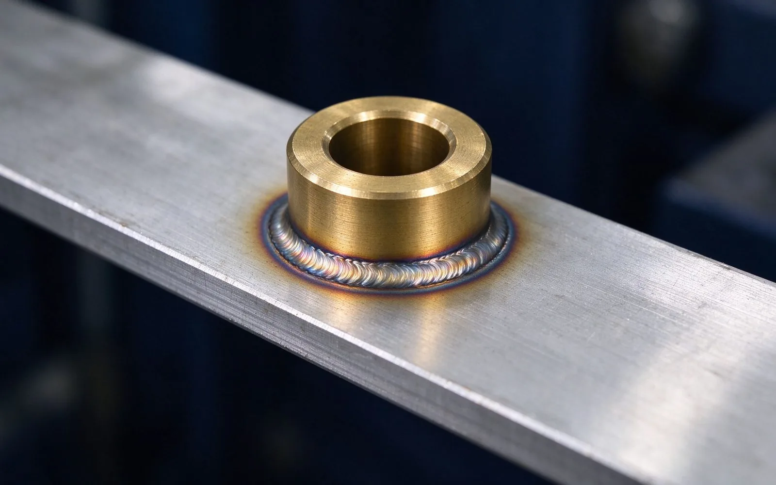
A busbar connection is only as good as its joint. Ultrasonic welds reach 0.005-0.169 mOhm
Read article
Thomas O'Brien is a manufacturing process engineer with 14 years in stamping, lamination and terminal machining for laminated busbars. He manages production lines for precision-cut profiles, insulation layering and CNC terminal processing, and focuses on dimensional control and repeatability at
Send the current profile, voltage class and terminal types — our engineers reply within one business day.