The weakest point of any busbar assembly is where it joins something else. Every connection method - ultrasonic welding, laser welding, resistance spot welding, bolted studs or blade contacts - trades process cost against contact resistance, heat input and field maintainability, and the right choice changes with the application. This guide compares the joining technologies used on laminated busbars by the numbers that matter: contact resistance, heat-affected zone, process speed, and service behaviour.
The weakest point of any busbar assembly is where it joins something else. Every connection method - ultrasonic welding, laser welding, resistance spot welding, bolted studs or blade contacts - trades process cost against contact resistance, heat input and field maintainability, and the right choice changes with the application. This guide compares the joining technologies used on laminated busbars by the numbers that matter: contact resistance, heat-affected zone, process speed, and service behaviour.
A busbar's own resistance is easy to control - it is a machined copper cross-section. The uncertainty lives in the joints: cell tabs, module terminals, inverter busbars and distribution rails all depend on connections whose resistance can vary by orders of magnitude with method, surface prep and torque. Published research on EV battery interconnects quantifies the range: contact resistance (ECR) in production-grade joints lands below 1 mΩ, and state-of-the-art processes reach below 0.01 mΩ, while poorly controlled laboratory or clamped contacts can sit tens of milliohms higher. Every extra milliohm at 300 A costs 90 mW of loss per milliohm - small per joint, decisive across a pack of hundreds.
The second reason the joint decides the assembly is heat input. Battery cells are temperature-sensitive; a joining method that injects heat into the cell terminal can damage the cell chemistry or the seal. The method selection therefore balances electrical performance, thermal exposure, mechanical strength and service access.
Ultrasonic welding bonds by friction and plastic deformation rather than melting. A sonotrode oscillates at 20-40 kHz under moderate clamping pressure, breaking surface oxides and allowing intimate metallic contact; because there is no bulk melting, the heat-affected zone is minimal, which makes the process ideal for temperature-sensitive parts like lithium-ion cell tabs and prismatic terminals. Published ECR data for ultrasonic welds on battery tabs ranges from about 0.169 mΩ down to 0.005 mΩ depending on material and parameters.
For dissimilar joints - the copper-to-aluminium interface that dominates battery packs - ultrasonic welding creates a 1-2 µm intermetallic transition layer in under two seconds per joint, with no filler, flux or adhesive. The trade-offs are: the process needs a rigid backing, the weld footprint is relatively wide, and it is a specialised machine investment. At SHANYUAN, ultrasonic welding is applied where the cell-interconnect duty demands it, alongside the terminal strategies described in the terminal connection guide.
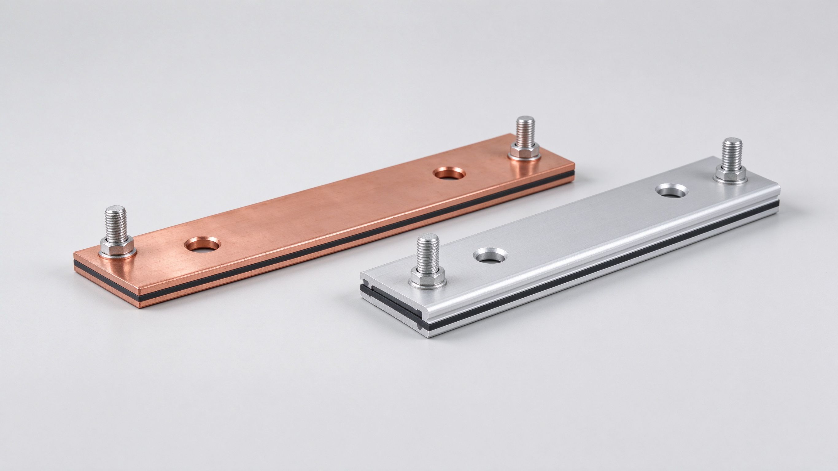
Laser welding concentrates a high-energy beam on the joint, melting and fusing the materials almost instantly, which leaves little time for oxidation and produces deep, strong joints close to base-metal strength. Fibre lasers in the 1-6 kW class at 1070 nm are the workhorses, with beam oscillation creating overlapping weld nuggets for consistent penetration. Copper's reflectivity is the classic challenge - green lasers (515 nm) improve absorption to around 65% versus IR sources, which is why green and blue laser sources are spreading in copper busbar welding.
Published ECR values for laser-welded battery connections reach about 0.130 mΩ, competitive with ultrasonic welding, while the weld spot can be smaller, enabling tighter cell packing. The trade-offs are heat input into the part (the melt pool must be managed to protect nearby cells), joint accessibility for the beam, and process monitoring depth. Laser welding is SHANYUAN's primary process for welded busbar assemblies where geometry and throughput favour it.
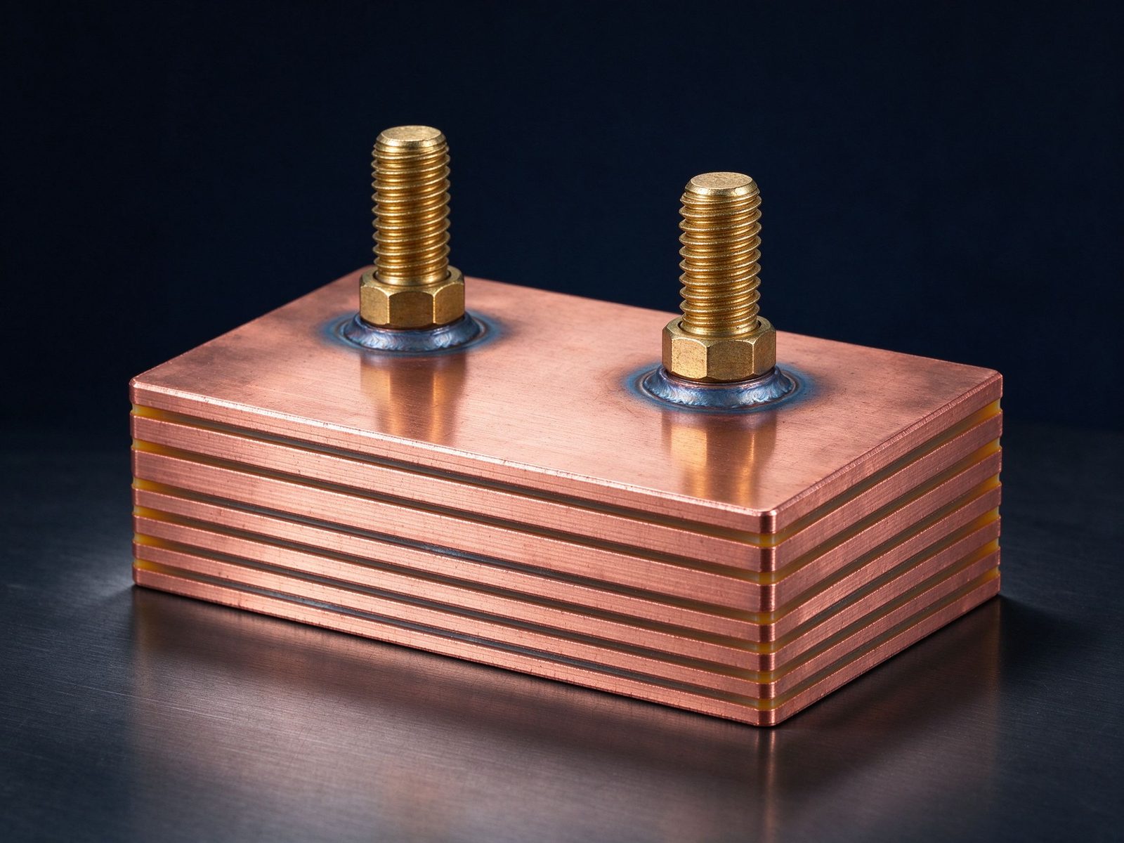
Resistance spot welding applies high current through the contacting parts to melt the interface. It is fast and simple, but published research notes a high likelihood of voids in the weld nugget, making it less suitable for high-current, fast-charging applications; ECR measurements in the literature range from 0.167 to 0.340 mΩ. For busbar duty that carries 100-1000 A continuously, that resistance band sits on the wrong side of the budget when better methods are available.
Resistance spot remains relevant for lightweight, low-current interconnects and where equipment simplicity matters. For power-carrying laminated busbars, ultrasonic and laser processes dominate; the selection is documented in the DFM checklist as part of the terminal strategy review.
Bolted stud connections - the M6/M8 stud, nut-and-spring-washer joints common on laminated busbars - remain the default where maintenance access and modular service are required. The engineering discipline is different from welding: contact pressure must be set by torque (with spring washers to preserve it across thermal cycling), surfaces must be plated for stable contact resistance (tin is standard), and the joint must be inspected periodically. Poorly set clamped contacts in research settings show ECRs as high as tens of milliohms, which is why torque specification and retention testing are production requirements, not suggestions.
Blade and plug-in contacts (e.g. busbar-to-busbar clip connectors) remove the torque variable entirely by using spring-loaded contacts, at the cost of a defined insertion force and a slightly higher contact resistance budget. The choice between stud, blade and weld is an application decision covered in depth by busbar connection practice and the terminal connection guide.
| Method | Typical ECR (mOhm) | Heat input | Service access | Typical use |
|---|---|---|---|---|
| Ultrasonic weld | 0.005 - 0.169 | Minimal (solid state) | None | Cell tabs, Cu-Al joints |
| Laser weld | ~0.130 | Local, manageable | None | Busbar assemblies, high throughput |
| Resistance spot | 0.167 - 0.340 | Local melting | None | Low-current interconnects |
| Bolted stud (torqued) | 0.1 - 1+ (process dependent) | None | Yes (re-torque) | Field-serviceable DC links |
| Clamp / blade contact | defined by spring force | None | Plug/unplug | Modular distribution rails |
Values are from published battery-interconnect research and supplier data; the right choice is application-specific, and the comparison makes the trade-off visible.
Battery packs mix copper and aluminium by design - aluminium for cell terminals and weight, copper for the high-current bus. The interface between them is metallurgically demanding: aluminium forms oxide instantly, and copper-aluminium intermetallics grow under heat, so the joint must be formed cold (ultrasonic) or with controlled energy (laser) and kept cool in service. Published process parameters for ultrasonic Cu-Al bonding - about 15 µm amplitude, 20 MPa pressure, 1.0 s duration - produce a reliable 1-2 µm transition layer with no filler, which is why ultrasonic is the reference process for cell-level Cu-Al joints.
For busbar-level dissimilar connections, plating is the companion strategy: nickel or tin plating on one side normalises the contact and prevents galvanic creep. The copper versus aluminium comparison explains the material logic behind these choices.
Welded busbar quality is assured in process, not by inspection alone. The control pyramid: process parameters locked per joint type (power, force, time, amplitude); in-line monitoring (weld energy, sonotrode impedance, laser power) with statistical process control; and destructive/non-destructive verification on a sampling plan - peel tests for ultrasonic joints, cross-section and pull tests for laser welds, resistance and X-ray on critical parts. Micro-ohmmeter measurement of the finished joint's resistance is the electrical gate that catches most process drift.
SHANYUAN's quality system documents weld parameters and verification data per lot, and the manufacturing process article walks through the full production sequence from stack-up to terminal joining.
The welded-versus-bolted decision is really a maintenance decision. A welded joint is permanent: lowest resistance, no torque policy, no re-torque schedule, and no field access - which suits battery packs, sealed modules and any connection that must never be touched again. A bolted joint is serviceable: the module can be replaced, the joint can be inspected, and the connection survives disassembly - which suits distribution rails, PDU interconnects and any part of the system with a maintenance plan. Blade and clip contacts sit in between: they are separable without tools but require a defined insertion force and have a slightly higher resistance budget.
The hybrid pattern emerging across 2026 designs is deliberate: weld the permanent, current-critical joints (cell-to-busbar, module-to-busbar) and bolt the serviceable ones (rack-to-string, PDU, main DC bus). The boundary is set by the maintenance philosophy of the system, not by convenience. The busbar connection practice page and the terminal connection guide lay out the decision matrix.
Soldering and brazing fill a narrower niche in busbar joining. Soldering (tin-lead or lead-free) is fast and forgiving, but the joint temperature limit (around 150-200 °C) and creep under thermal cycling disqualify it for most power-carrying joints; it persists in low-current, low-temperature signal and small-assembly roles. Brazing (silver-based filler above 450 °C) creates strong, high-temperature joints and is used where a large, permanent connection is needed without the capital of welding - for example joining thick copper sections or dissimilar metals - but the heat input requires careful management around heat-sensitive components and plating can be damaged.
The engineering rule is simple: for high-current busbar duty, prefer solid-state or controlled-energy welding; reserve solder and braze for applications where the temperature budget and creep behaviour have been verified. The same logic appears in material-pairing guidance like copper versus aluminium.
The electrical gate for every joined busbar is the micro-ohm measurement: a four-wire micro-ohmmeter applies a defined current (often 10 A class) and measures the millivolt drop across the joint, yielding contact resistance in micro-ohms. Acceptance values are set per joint type and current class - a cell-level ultrasonic joint may be accepted below a few hundred micro-ohms, a bolted DC-link joint below a defined value with the torque applied. The measurement catches process drift before it becomes field failure, and it is cheap enough to run as a routine gate.
The companion verification is thermal: under rated current, the joint's temperature rise must stay inside the design budget, and a joint that runs hot at acceptance will only run hotter in service. Together, resistance and temperature measurements form the two acceptance gates that SHANYUAN documents per lot in the quality system - the same evidence buyers should request in their qualification audit.
With this checklist, the buyer can compare joining capability objectively and avoid the trap of evaluating suppliers on price per weld alone.
In series production, joining is a station in a flow, not an isolated process. The typical laminated busbar line runs: material incoming inspection (copper alloy certificates, dielectric certificates) → cutting and stamping → cleaning and plating (if tin or nickel) → lamination (dielectric bonding under controlled temperature and pressure) → terminal joining (welding, stud attachment or blade brazing) → testing (hi-pot, resistance, dimensional, and sample PD/thermal) → packing and traceability labelling. The joining station is where the most process risk concentrates, which is why weld parameters are locked per joint type and monitored statistically.
The line view explains three realities buyers encounter. First, joining capability is embedded in the line investment: ultrasonic and laser stations plus verification equipment are capital, not overhead. Second, lead times are set by the slowest verified station, not by stamping throughput. Third, quality claims live or die on the joining data - which is why the manufacturing process article and the quality system documentation are the right starting points for supplier evaluation.
| Application | Typical joint | Why |
|---|---|---|
| Cell tab to cell interconnect | Ultrasonic weld | Solid state, minimal heat, Cu-Al capable |
| Module busbar to terminals | Laser weld or stud | Throughput + strength, or service access |
| Inverter DC link to devices | Laser weld / press-fit | Low inductance, low resistance, tight layout |
| Rack/string distribution | Bolted with spring washers | Field service, re-torque policy |
| Main DC bus (container) | Bolted or welded (per policy) | Highest current; maintenance philosophy decides |
The map is a starting point, not a rulebook - the final choice follows voltage, current, thermal and maintenance requirements, using the decision logic in busbar connection practice and the terminal connection guide.
Joining technology is not static, and three developments are worth watching in 2026. First, green and blue laser sources are maturing for copper: the 515 nm green wavelength improves absorption to roughly 65% versus IR, enabling faster, more consistent copper welds with less spatter - directly relevant to busbar and cell-interconnect production. Second, hybrid processes are emerging - ultrasonic pre-bonding followed by laser reinforcement, or resistance pre-heating before laser fusion - to combine the advantages of solid-state and fusion joining. Third, in-process monitoring is getting smarter: weld energy, acoustic signatures and thermal imaging feed real-time quality models that flag drift before it becomes a defect.
For buyers, the practical implication is to check the supplier's process roadmap during qualification: a supplier investing in green-laser and in-line monitoring capability is positioning for the higher-throughput, higher-reliability programs that are coming with 800 V platforms and megawatt charging. SHANYUAN's process development follows this roadmap, and the manufacturing process article describes the line architecture that hosts these capabilities.
Ultrasonic welding reaches 0.005-0.169 mOhm in published battery-joint data, with laser welding around 0.130 mOhm - both far below poorly controlled bolted contacts.
It is solid-state (no melting), so heat input and the heat-affected zone are minimal, protecting temperature-sensitive cells.
When field service and modular replacement are required - but torque specification, spring washers and periodic re-torque are mandatory to keep contact resistance stable.
Yes - ultrasonic welding creates a controlled 1-2 um intermetallic layer; laser welding with green sources is the fast alternative, and plating handles galvanic concerns.
Continue with insulation testing for the finished assembly, thermal management for the operating envelope, and the day's market article for the business context.
The joining decision is where reliability is really made: process choice, parameter control, verification measurement and maintenance philosophy together determine whether the assembly delivers its rated current for decades. A buyer armed with the resistance numbers, the process map and the supplier checklist can compare proposals on engineering merit rather than price alone.
Whatever the process, the acceptance logic is the same: specify the joint's electrical and mechanical targets, lock the process parameters, measure every critical joint, and document the evidence. Joining done that way is not a manufacturing detail - it is the foundation of the assembly's reliability.
From cell tabs to container bus, the joining discipline is one: know the resistance budget, control the process, measure the joint and document the evidence. Suppliers that live by that discipline make the reliability argument in numbers, and buyers who ask for the numbers make decisions that hold up in the field.
In practice, the choice between ultrasonic, laser, resistance and bolted joining is decided by four questions: how much current, how much heat the part can absorb, whether the joint must be serviceable, and what evidence the program requires. Answering those four questions honestly - before tooling, before series release - is the entire art of busbar joining.
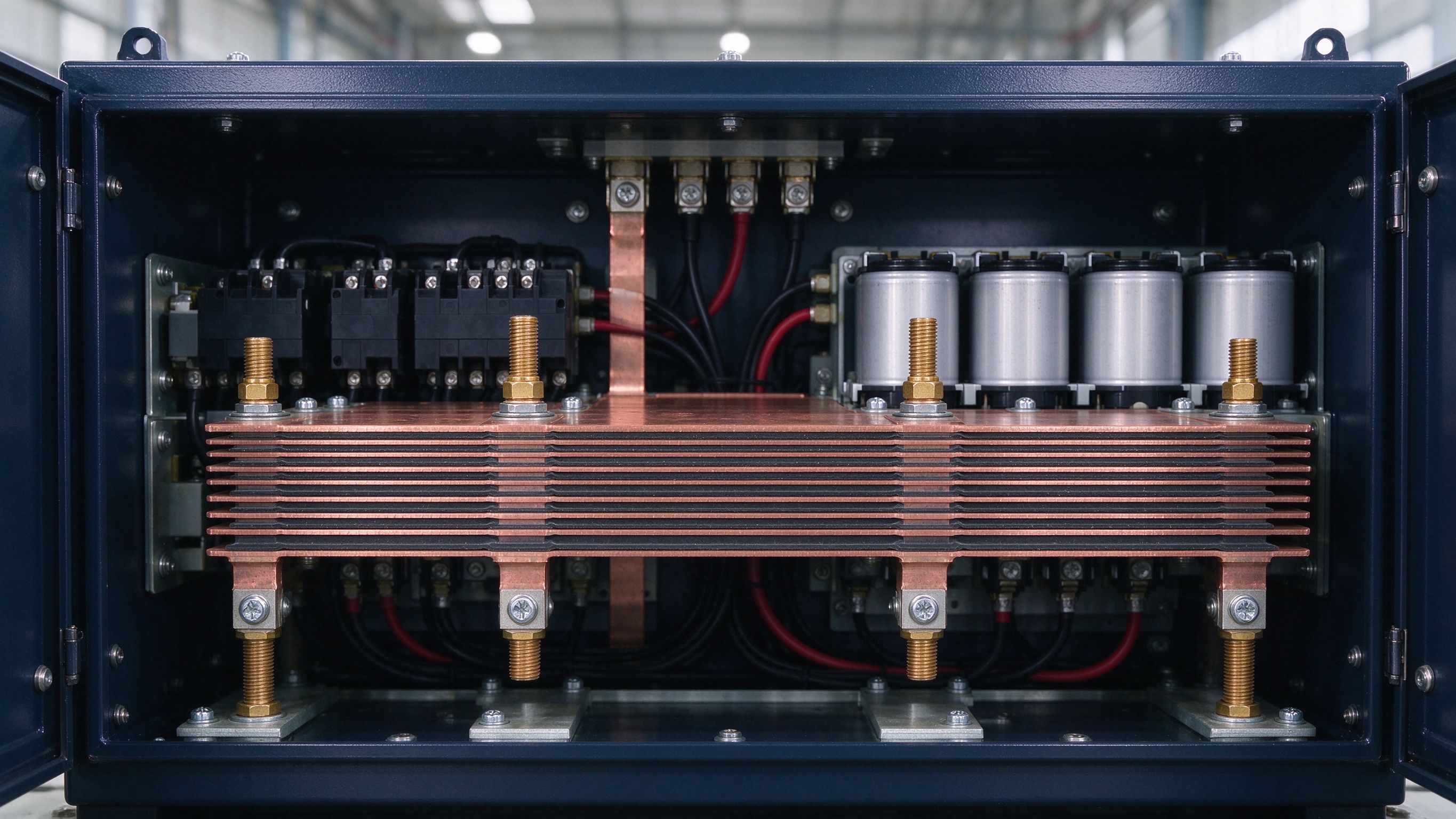
MCS moves from pilot to fleet scale in 2026: 1 MW+ charging at 1250 V and up to 3000 A mak
Read article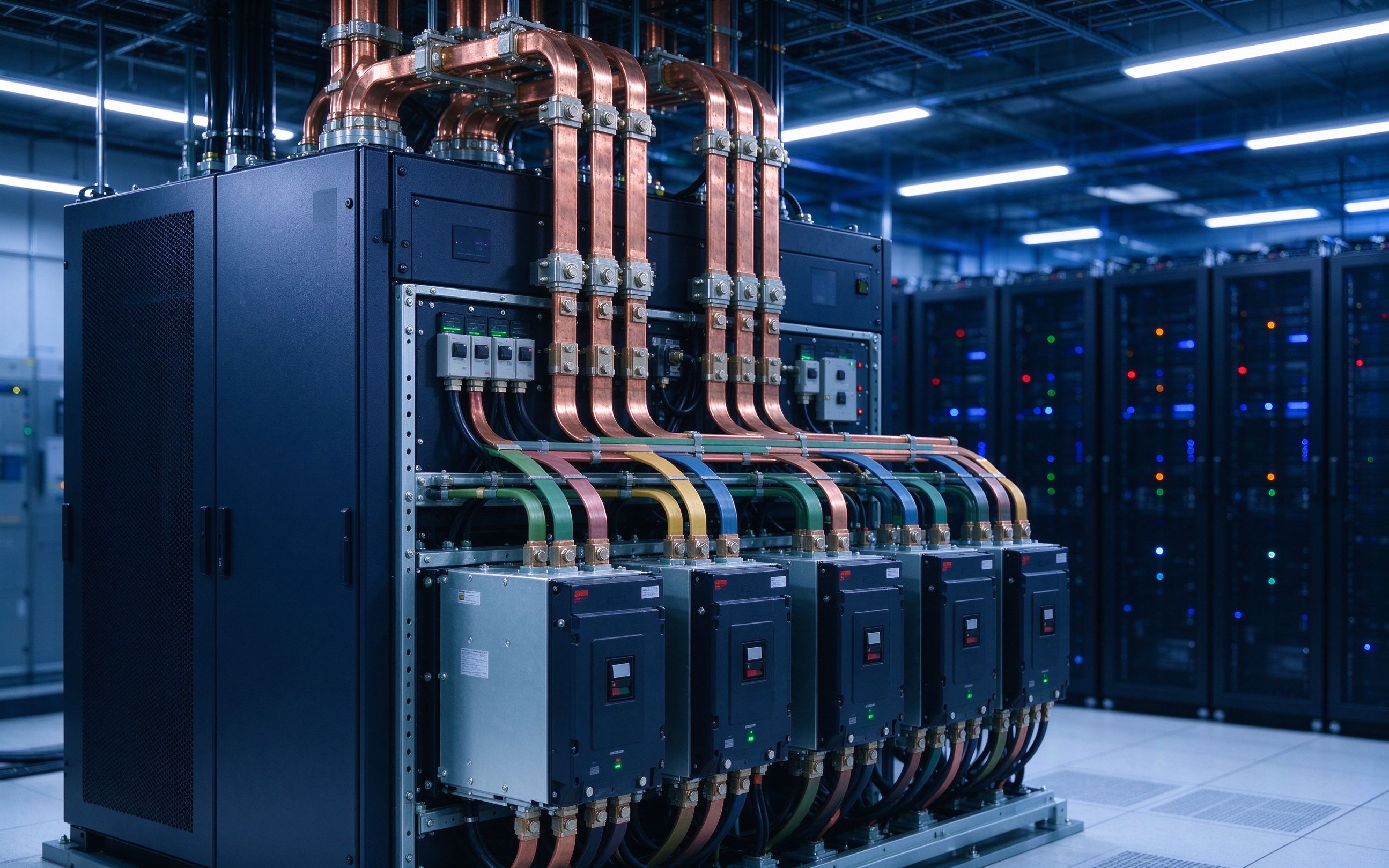
BloombergNEF sees 158-188 GW of new energy storage in 2026. PCS platforms are climbing fro
Read article
Multiple forecasters put the laminated busbar market near USD 1.0-1.06 billion in 2026, wi
Read articleSend the current profile, voltage class and terminal types — our engineers reply within one business day.
Send drawings, current ratings and voltage class — DFM feedback and a quotation within one business day.
