A laminated busbar can be perfectly designed, perfectly pressed and perfectly tested — and still fail in service if the terminal is wrong. Too small a stud and the joint overheats; wrong torque and the joint relaxes after a few thermal cycles; wrong welding process and the nugget cracks; wrong fuse link and it does not blow when you need it to. At SHANYUAN we build four terminal types into our laminated busbars every day — M6/M8 threaded studs, blade terminals, welded tabs and fuse links. This guide explains how each one is built, where it is used, and what torque and welding numbers matter in the field.
A laminated busbar can be perfectly designed, perfectly pressed and perfectly tested — and still fail in service if the terminal is wrong. Too small a stud and the joint overheats; wrong torque and the joint relaxes after a few thermal cycles; wrong welding process and the nugget cracks; wrong fuse link and it does not blow when you need it to. At SHANYUAN we build four terminal types into our laminated busbars every day — M6/M8 threaded studs, blade terminals, welded tabs and fuse links. This guide explains how each one is built, where it is used, and what torque and welding numbers matter in the field.
The copper inside a well-designed laminated busbar rarely fails. It is the joint — where the busbar meets another conductor, a lug, a PCB pad or a fuse — that accumues resistance, heat and relaxation over years. Every factor that drives hotspot temperature concentrates at the terminal:
Choose the terminal type at DFM stage, not after the drawing is frozen. See our 2026 DFM checklist for the terminal-related checks we run on every custom busbar quote.
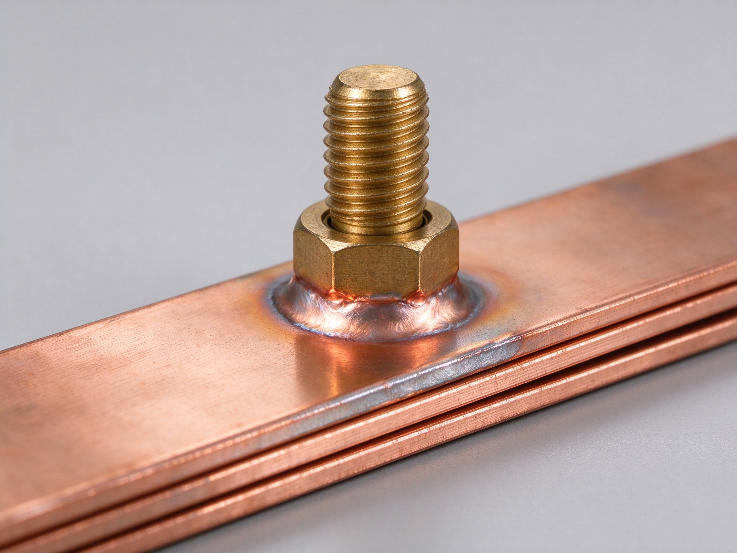
A threaded stud is either pressed into a punched hole in the copper layer (with a serrated or flanged body that locks into the sheet) or resistance-welded onto the layer. SHANYUAN uses both methods depending on current and service expectations. The stud protrudes through the dielectric and outer insulation so a customer can bolt a lug or bus frame directly to the busbar.
Studs are the right terminal when the customer needs to field-remove the connection (maintenance, swapping a fuse, replacing a module) and when current is continuous and bolted. They are the standard on power-electronics busbars and on most inverter DC links. For current sizing context, see the current capacity article.
A blade terminal is a flat, rectangular tab formed directly out of the copper layer — the same sheet, extended outward. The customer clips a mating connector over the blade. No bolt, no tool at the joint.
Blades win on assembly time and on vibration-prone applications where a clipped connector locks mechanically. They lose on very high currents, where a bolted joint spreads pressure better than a single clip contact. We most often see blades on battery busbars that plug into a BMS or a service disconnect, and on lower-current signal and sense taps.
A weld tab is a secondary copper shape that has to be attached somewhere the main blank cannot reach — for example, a tab that breaks out to a sensor, a ground point or a parallel module. SHANYUAN typically joins these by resistance welding (projection or spot welding) or ultrasonic welding, depending on material stack and current.
A fuse link is a controlled-neck section of copper in the current path. Under normal current it is just another conductor; under a fault current it heats faster than the rest of the bus and melts, opening the circuit. Fuse links are common in battery interconnects, DC combiner boxes and some string inverters.
We see fuse links most often in energy storage and EV battery builds where a cell-level short has to be isolated without taking down the whole string. Pair with the layer and plating guidance in the manufacturing process.
| Terminal type | Typical use | Current range | Field serviceable? | Key check |
|---|---|---|---|---|
| M6 stud | Bolted lugs, bus frame, inverter DC link | Up to ~150–200 A per stud | Yes | Torque 6–8 N·m; flat washer |
| M8 stud | Higher-current bolted joints | Up to ~250–400 A per stud | Yes | Torque 10–14 N·m; re-torque after first cycle |
| Blade tab | Plug-in connectors, BMS taps, lower-current breaks | Tens of amps to ~100 A | Yes (connector swap) | Matches connector datasheet exactly |
| Weld tab | Break-out to inaccessible points, sensors, grounds | Depends on nugget | No | Unplated weld zone, clean before weld |
| Fuse link | Cell/string protection, ESS combiner, EV packs | Rated by neck | Replaceable as assembly | No holes in neck; visible and accessible |
Current ranges are practical rules of thumb, not limits; the real number always depends on copper cross-section and derating per the ampacity chart.
A quick decision flow before you release the drawing:
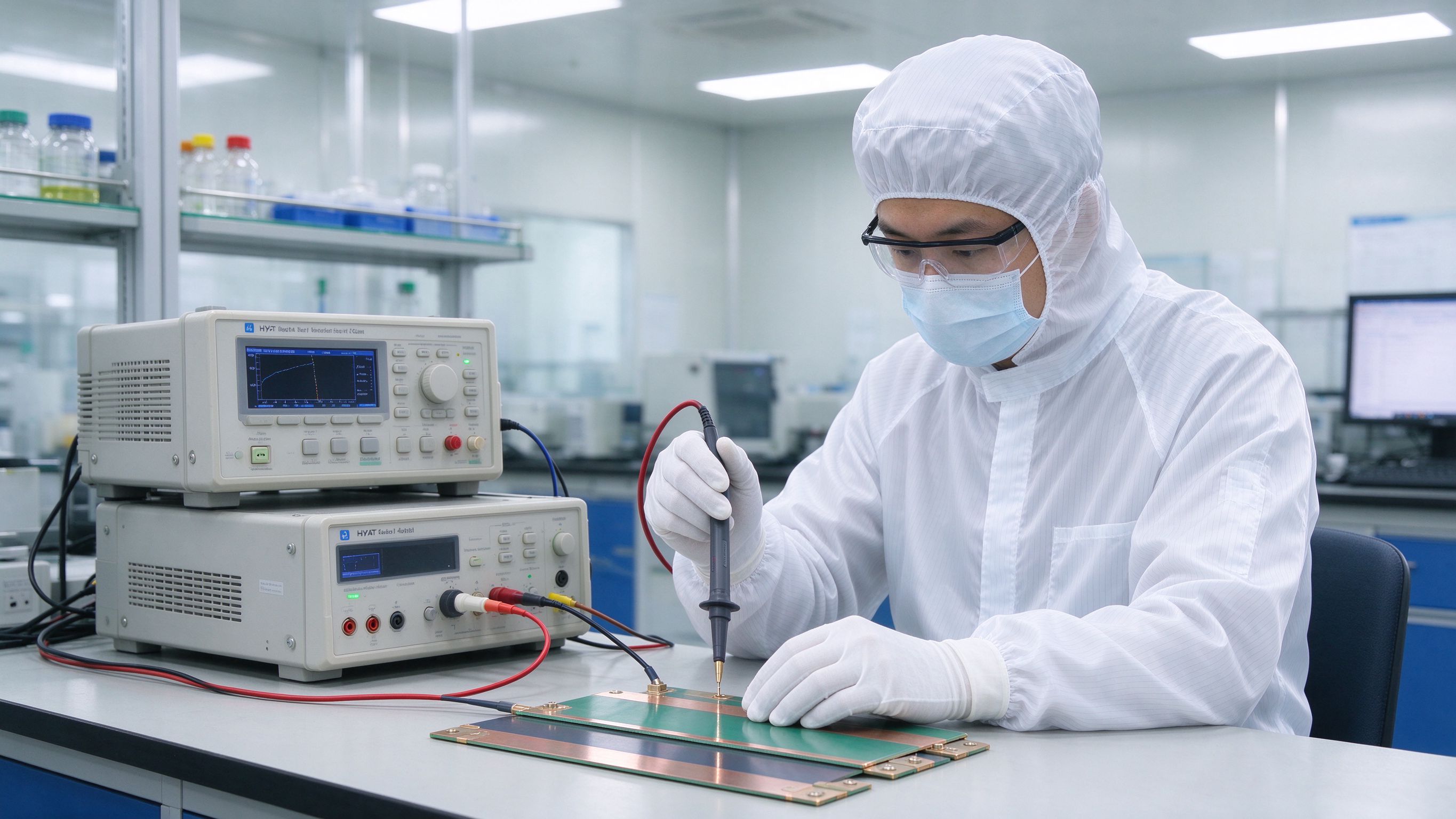
When you buy laminated busbars, the terminal section is where suppliers differ most in process and quality. A cheap laminated busbar price that skips stud pull-strength testing or weld-zone masking will show up in the field. SHANYUAN runs a busbar OEM build with standard hipot, insulation resistance, dimensional, visual and continuity tests on every batch, and terminal details are locked at DFM. If you want a quote, send the drawing to busbar@shanyo.com or use /contact/ — samples in 5–7 working days, production 2–3 weeks, no sample MOQ, sea or air freight worldwide. See also the design guide, busbar vs cable and the busbar design guide.
A bolted joint is not a continuous conductor; it is a contact between two surfaces that touch at a microscopic set of high points. The contact resistance depends on contact pressure, surface flatness and surface finish. Bare copper oxides over time, and that oxide layer has a much higher resistivity than copper itself — which is why we tin-plate every exposed contact surface on our busbars. Tin keeps the contact resistance low and stable across thousands of thermal cycles, and it prevents the oxide growth that would otherwise make the joint run hotter year after year. At a properly torqued, tin-plated M8 stud, contact resistance should stay in the tens of micro-ohms range; if it climbs into the milli-ohms, something has relaxed or corroded.
In mobile and traction equipment — EV powertrains, heavy trucks, rail — busbar joints see continuous vibration and thermal cycling. Two design rules keep the joint reliable: use a flat washer under the nut to spread load, and choose a torque that leaves the stud in its elastic region, not stretched past yield. Spring washers are not a substitute for correct torque; in fact they can sometimes reduce long-term clamping pressure because they relax. For safety-critical joints we recommend a re-torque check after the first thermal cycle, and then periodic inspection on a maintenance schedule. We discuss the mechanical side of this in the DFM checklist, and the thermal sizing side in the current capacity article.
Changing a terminal style after first article means re-cutting copper blanks, re-plating, re-laminating and re-testing. If a drawing says "hole M6" and the customer later needs a press-in M8 stud, the whole part changes. That is exactly why our DFM review asks about terminal style, protrusion height, mating connector, torque and re-torque schedule before we quote. It is also why we ask for the mating lug or connector part number — the pitch, thickness and contact area are defined by that mating part, not by our busbar. Get those details on the drawing before release and the first sample usually fits the first time.
To recap the practical takeaway: choose M6/M8 studs for removable bolted power joints, blade tabs for clip-on connectors, weld tabs for inaccessible break-outs, and fuse links where you want intentional over-current protection. Keep weld zones unplated, torque studs to the right value with a flat washer, and re-check torque after the first thermal cycle. If you are unsure which combination fits your inverter, battery pack or converter, send the mating hardware part numbers to our engineering team with the drawing; we will lay out the terminals, quote the part and ship samples in 5–7 working days. We are a dedicated busbar manufacturer based in Rizhao, shipping worldwide, and terminal selection is one of the questions we answer fastest on every custom busbar quote.
Every hour spent on DFM before a custom busbar quote saves a week of rework. This is the c
Read article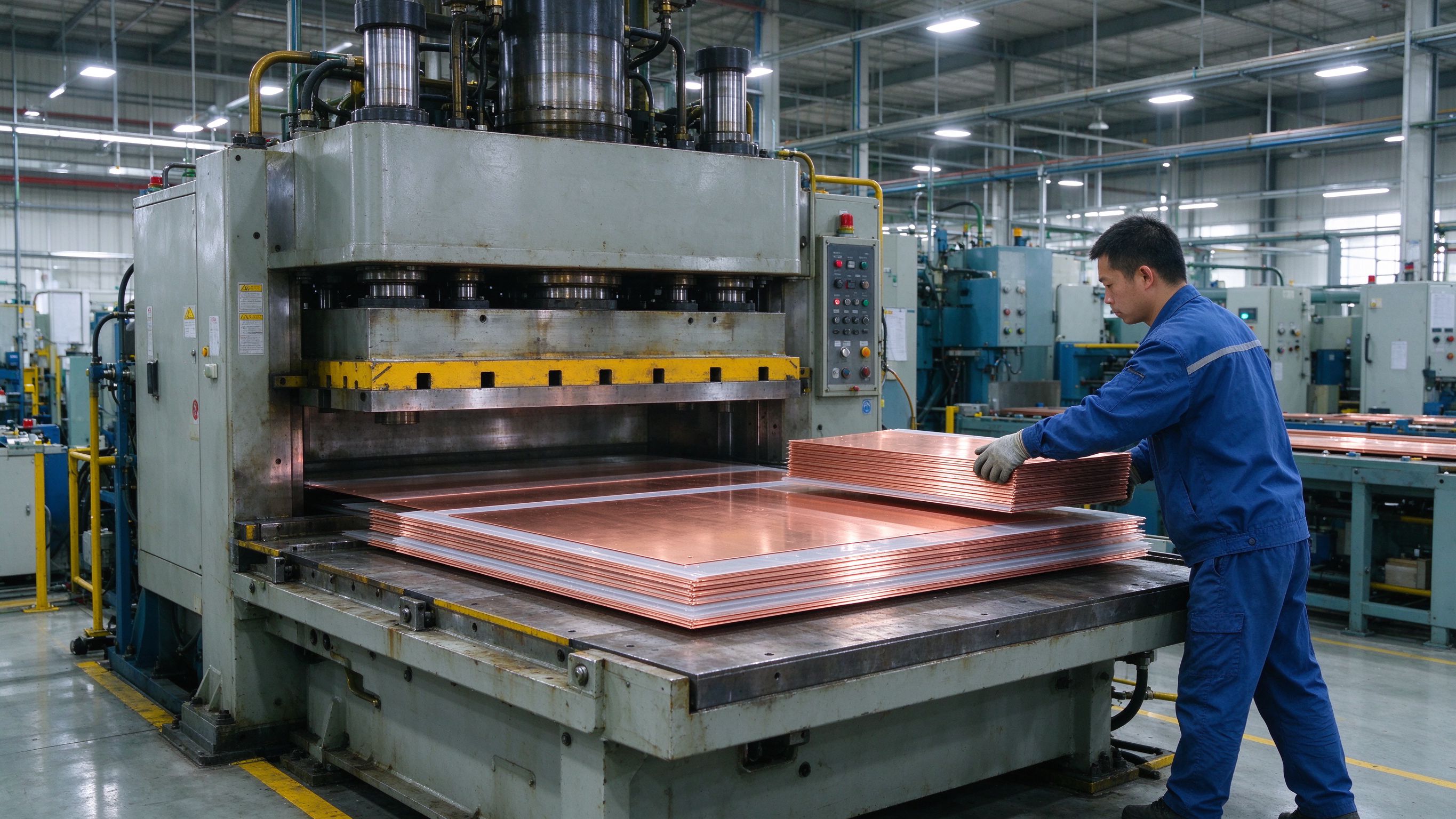
From C11000 copper coil to a fully sealed, tested multi-layer busbar, this walkthrough exp
Read article
Copper busbar current rating is not a single number. It is a starting ampacity adjusted by
Read articleSend the current profile, voltage class and terminal types — our engineers reply within one business day.
Send drawings, current ratings and voltage class — DFM feedback and a quotation within one business day.
