The field failure that takes a converter offline does not happen in a day — it trends for months, and the trend is readable if anyone is watching. A hot joint shows up in thermal imaging weeks before it trips, a contact-resistance climb is visible in micro-ohm measurements months before that, and a torque change is measurable at every service interval. This guide is the maintenance and troubleshooting playbook for laminated and bolted busbars: what to measure, when to measure it, and how to decide whether to repair or replace.
The field failure that takes a converter offline does not happen in a day — it trends for months, and the trend is readable if anyone is watching. A hot joint shows up in thermal imaging weeks before it trips, a contact-resistance climb is visible in micro-ohm measurements months before that, and a torque change is measurable at every service interval. This guide is the maintenance and troubleshooting playbook for laminated and bolted busbars: what to measure, when to measure it, and how to decide whether to repair or replace.
Maintainability is decided at the drawing board: whether joints are accessible, whether torque marks exist, whether the plating survives inspection, whether the busbar can be serviced in place or must be removed. A design that anticipates maintenance — labeled terminals, documented torque values, accessible joints, inspection windows — costs a fraction of the lifetime maintenance of a design that does not. Buyers should put maintainability in the specification, not discover its absence in year two.
The maintenance plan itself is simple in structure: periodic inspection, measured parameters with baselines, and repair criteria. What separates a good plan from a decorative one is that the measurements are load-corrected, trended and acted on. The failure-mode engineering behind this is covered in our busbar failure-mode selection guide — the maintenance plan is the mirror image of the selection rules.
A busbar maintenance plan has three tiers. The annual tier: thermal imaging under load, visual inspection, torque verification on critical joints, contact-resistance spot checks. The multi-year tier: full joint preparation on the highest-duty connections, plating condition assessment, insulation and PD checks where voltage warrants. The event tier: inspection after any fault, overload, vibration event or environmental exposure, plus the first-year retorque that catches the initial relaxation of new joints.
The scope scales with duty. A distribution busbar in a benign indoor environment needs the annual tier and little else; a storage DC-link cycling daily needs the full program plus trending. The interval decision belongs to the engineer who knows the duty — the maintenance plan should be written against the same duty envelope as the design.
Thermal imaging is the first-line tool because it sees the symptom directly: a joint hotter than its neighbors under the same current is a joint with elevated resistance. The method has one hard rule — the inspection must happen while the equipment is energized and under load. A connection that is barely warm at 30% load may be dangerously hot at 90% load, which means scanning at low load produces clean pictures and false confidence. Where possible, schedule the scan during peak demand periods to capture the worst-case thermal profile.
The comparison that matters is joint-to-joint under identical current: the same load, same ambient, same emissivity. That is why a baseline thermal image taken at commissioning is so valuable — the first year's comparison tells you which joints are drifting before any limit is approached.
Raw hotspot temperatures are not directly comparable across visits because the load differs. Load correction adjusts the measured temperature to a reference load using the I2R relationship: the temperature rise scales with the square of current. A joint measured at 55°C at 400 A can be compared to its baseline at 500 A by correcting the rise. Without the correction, the maintenance team cannot tell a real trend from a load difference.
The correction math is straightforward but must be done consistently — record the load at scan time, apply the same reference, and trend the corrected rise. Suppliers can provide the thermal data for their designs; the discipline of recording and correcting is the plant's to implement.
Thermal imaging only catches defects under substantial electrical load. The earlier and more precise tool is the digital low-resistance micro-ohmmeter, which measures the contact resistance of a joint in micro-ohms while the equipment is de-energized. Micro-ohm spikes caused by under-torqued bolts, oxidation or plating degradation show up as measurable resistance changes long before they produce a thermal signature, allowing teams to remediate faults during scheduled outages before heat damage begins.
The discipline is trending, not absolute values: record each joint's resistance at every outage, compare to the baseline and to the adjacent joints. A joint that climbs steadily is failing even if every individual reading looks benign. The same measurement validates a repair — the fix is complete when the resistance returns to the baseline band.
Bolted joints relax. Copper creeps under thermal cycling, plating compresses, washers bed in, and the clamp force — the thing that actually carries the current — decays even though the bolt still feels tight to a wrench. The maintenance response is torque verification with a calibrated tool against the documented value, applied on a schedule matched to the duty. For new installations, the first-year retorque is the critical one: most relaxation happens in the first thermal cycles.
Retorque alone, however, is not a repair. Field data shows the pattern clearly: connections that receive full joint preparation — disassembly, cleaning, fresh antioxidant compound, reassembly to specification — improve in about 92% of cases, versus roughly 20% for simple retorquing. The takeaway: torque verification finds the joints, and joint preparation fixes them.
When a thermal image or micro-ohm reading identifies a hot joint, the repair is a procedure, not a tightening. De-energize, isolate and prove dead under the approved procedure. Disassemble the joint. Assess the surfaces — contamination, oxidation, damaged plating, fretting. Clean both faces to the correct finish. Apply fresh antioxidant compound where the plating system calls for it. Reassemble with the correct washers and hardware to the documented torque, in the documented sequence. Then verify with a micro-ohm measurement and a follow-up thermal scan under load.
Do not treat tightening as the default repair. A hot connection may involve contamination, oxidation, damaged plating, wrong hardware, inadequate contact area, poor alignment, conductor creep, incorrect washer arrangement or loss of spring force — a torque wrench fixes none of those. The joint preparation data is unambiguous, and the maintenance plan should treat it as the standard procedure.
Visual inspection catches the slow degraders that measurements miss until late. Terminal discoloration — a darkening or streaking on the plating — is the visible signature of a joint running hot or corroding. Plating wear at contact edges, fretting marks around bolted interfaces, and contamination films on insulation surfaces are all readable by an experienced eye during the annual visit. The discipline is to record what is seen, photograph the same joints each year, and compare.
Four signals matter most: a change in torque reading at a joint, a rising contact resistance trend, a thermal image showing one joint hotter than its neighbors under the same load, and visible discoloration at the terminal. Each alone is a hint; two or more together are a clear signal that the joint needs attention. The plating and corrosion guide explains what the visible signs mean electrochemically.
Above a few hundred volts, the insulation system deserves its own inspection track. Partial-discharge testing at a fixed voltage and condition gives a number that trends: a rising PD level on the same busbar over successive outages is insulation degradation in progress. Where the busbar operates near the PD inception voltage — outdoor, humid or high-altitude installations — the check interval should be shorter and the conditions recorded.
Dielectric and insulation-resistance measurements catch moisture ingress and surface contamination, the two environmental killers. The insulation testing guide covers the test methods; the maintenance point is that insulation is a consumable with a trend, and the trend must be measured to be known.
The repair-or-replace decision follows a short rule set. A bolted joint with degraded plating but sound structure: repair — joint preparation restores it, and the data says 92% of prepared joints improve. A laminated busbar with insulation breakdown, delamination or edge damage: replace — the laminate is the barrier, and patching it is not a reliable repair. A welded joint with a visible crack: replace or cut-and-resplice per the manufacturer's procedure — never patch a cracked weld. A busbar that has seen a short-circuit event: inspect the whole assembly for deformation before deciding anything.
The commercial rule is equally simple: a busbar is a fabricated part with a documented design life, and the repair decision should be made against the failure-mode analysis, not against the price of a replacement. Where the laminate or the structural integrity is compromised, replacement is the reliable and the honest answer.
The maintenance program's value lives in its records. Each joint needs a stable identity, a baseline and a trend line: torque readings, micro-ohm values, thermal rise at reference load, visual condition, repair history. The trend is the early-warning system — a joint that climbs 10% per outage over three outages is scheduled for preparation before it becomes a trip. Without the records, every inspection is a snapshot with no context and no predictive value.
The same discipline that makes a maintenance program work is what separates suppliers in the qualification conversation: the reliability file with documented test evidence, cycling data and plating standards. Our quality documentation ships that file with the hardware, and the thermal cycling reliability guide explains how the evidence was generated.
The inspection schedule should mirror the failure-mode map of the application, not a generic calendar. A storage DC-link that cycles daily gets joint trending every outage and a first-year retorque that is non-negotiable. An outdoor solar interconnection gets PD checks tied to humidity seasons and plating inspections after weather events. A rail or marine busbar gets vibration-attentive inspections — hardware checks, weld inspections, support condition — on a shorter mechanical interval. The failure-mode selection guide published today maps each duty to its dominant modes; the maintenance plan is that map read backwards.
Scheduling against failure modes is also the cost-efficient answer: the inspections that matter are prioritized, and the ones that would only generate paperwork are deferred. A maintenance budget spent on the right joints beats one spread evenly across all of them.
Three scenarios cover most field calls. One hot joint among many: compare neighbors, correct for load, measure micro-ohms at the outage, schedule joint preparation — the thermal image is a symptom, the resistance is the diagnosis. Uniformly hot busbar: the problem is sizing or ambient, not the joint — check the temperature-rise design against the actual load and ambient, and consult the ampacity chart for the headroom. PD noise or tracking on the insulation: the environment or the material is the issue — check humidity, contamination and the PD-free design rules before replacing parts.
In each case the discipline is the same: measure before disassembling, correct before concluding, and document before repairing. The scenario that looks like a mystery is almost always a load or environmental difference that the measurement plan would have caught.
Busbar maintenance is live-adjacent work, and the safety discipline is not negotiable. Thermal imaging runs energized by design, which means approach distances, insulated tools and a documented procedure. Every contact-level task — torque, micro-ohm measurement, joint preparation — runs de-energized: isolate the circuit, prove dead with an approved tester, apply the lockout-tagout, and work against the manufacturer's instructions. Never work a busbar on the assumption that it is dead.
The plant procedure should be written for the specific installation — the voltage, the energy storage in the DC link (capacitors hold charge after de-energizing), and the discharge procedure come first. This is the difference between a maintenance program and a safety incident waiting for a schedule. The engineering team can confirm design documentation and discharge guidance for the specific busbar system.
A good busbar supplier provides the maintenance kit along with the hardware: the torque values, the joint design drawings, the plating specification, the test evidence and the inspection guidance. The maintenance plan should be written from that documentation, not invented by the plant. Where the documentation is missing, the first maintenance task is to obtain it — a busbar without its torque and plating documentation is a liability, not an asset.
At SHANYUAN the quality system documents every shipped design, and the factory tour shows the test capability behind the evidence. For an existing installation, contact the engineering team with the part details and the duty — the maintenance schedule, the torque values and the inspection checklist are part of the product, not an afterthought.
Some inspection triggers are calendar-based and some are weather-based, and both belong in the plan. Humidity seasons are the natural trigger for insulation and PD checks on outdoor installations; heat waves are the natural trigger for load-corrected thermal imaging at peak demand; storm or flood events trigger the post-event inspection of enclosures, plated surfaces and joint torque. The environmental envelope of the site — not just the calendar — sets the schedule.
The same envelope should have shaped the selection: failure-mode-driven selection assigns the dominant modes by environment, and the maintenance plan is the mirror. A coastal storage site and an inland data center do not need the same schedule, and the connection design resources carry the environmental design guidance that matches.
A maintenance program runs on a data template, not on memory. Each joint needs an identity, a baseline, and a trend: torque reading, micro-ohm value, corrected thermal rise, visual condition, repair history — one row per joint per inspection. The template is the early-warning system, because a joint climbing 10% per visit is scheduled for preparation long before it approaches a limit, while the same joint inspected fresh each time looks fine forever.
The quality documentation SHANYUAN ships with every design provides the starting points — torque values, plating specification, test evidence — so the plant's baseline is the supplier's engineering, not an assumption. The template then turns inspections into numbers the team can actually trend.
The best maintenance plan fails at the hands that execute it. Training covers the procedure — load-corrected imaging, micro-ohm measurement, joint preparation, torque sequence — and the judgment: when a reading is a trend versus a snapshot, when a joint needs preparation versus replacement, when a thermal image is load-limited versus genuinely hot. The people who touch the joints need both the tool skill and the decision rules.
The practical training package includes the manufacturer's documentation, a supervised first campaign, and a review of the trend data at each cycle. For an installation where the original documentation is thin, the first maintenance task is to reconstruct it — our custom busbar program and engineering team can regenerate the torque values and inspection guidance from the part details.
Maintenance budgeting should follow the failure-mode map, not an equal annual allowance. The expensive years are the first (the critical first-year retorque and commissioning baseline) and the later ones (plating refresh, insulation trending, and the repair-or-replace decisions on the highest-duty joints). The middle years cost little if the design was right; the total over 20 years is a fraction of the replacement cost of the busbar — and an even smaller fraction of the cost of a plant outage.
The budget conversation now includes the metal market: replacement busbar prices follow the copper supply situation, so deferring a replacement into a tight metal market costs more than scheduling it. The 25-year assets of the long-duration build-out and the fleets of Indian storage programs are being budgeted against the same reality, and the EMI and measurement discipline of the power stage is part of the same asset-management picture — the measurement trend protects the investment in every domain.
How do I detect a failing busbar joint before it fails? Three signals trend before failure: a rising contact resistance in micro-ohm measurements, a thermal hotspot that grows relative to neighbors under the same load, and a torque reading that drifts from baseline. Any two together are a clear signal to schedule joint preparation. How often should a bolted joint be retorqued? At minimum the first-year retorque on new installations, then per the duty: annually for daily-cycling systems, at multi-year intervals for benign duty, and immediately after any fault or vibration event. Is retorquing enough to fix a hot joint? No — field data shows full joint preparation fixes about 92% of hot connections versus 20% for simple retorquing. Clean, prepare, reassemble to specification, and verify with a micro-ohm measurement.
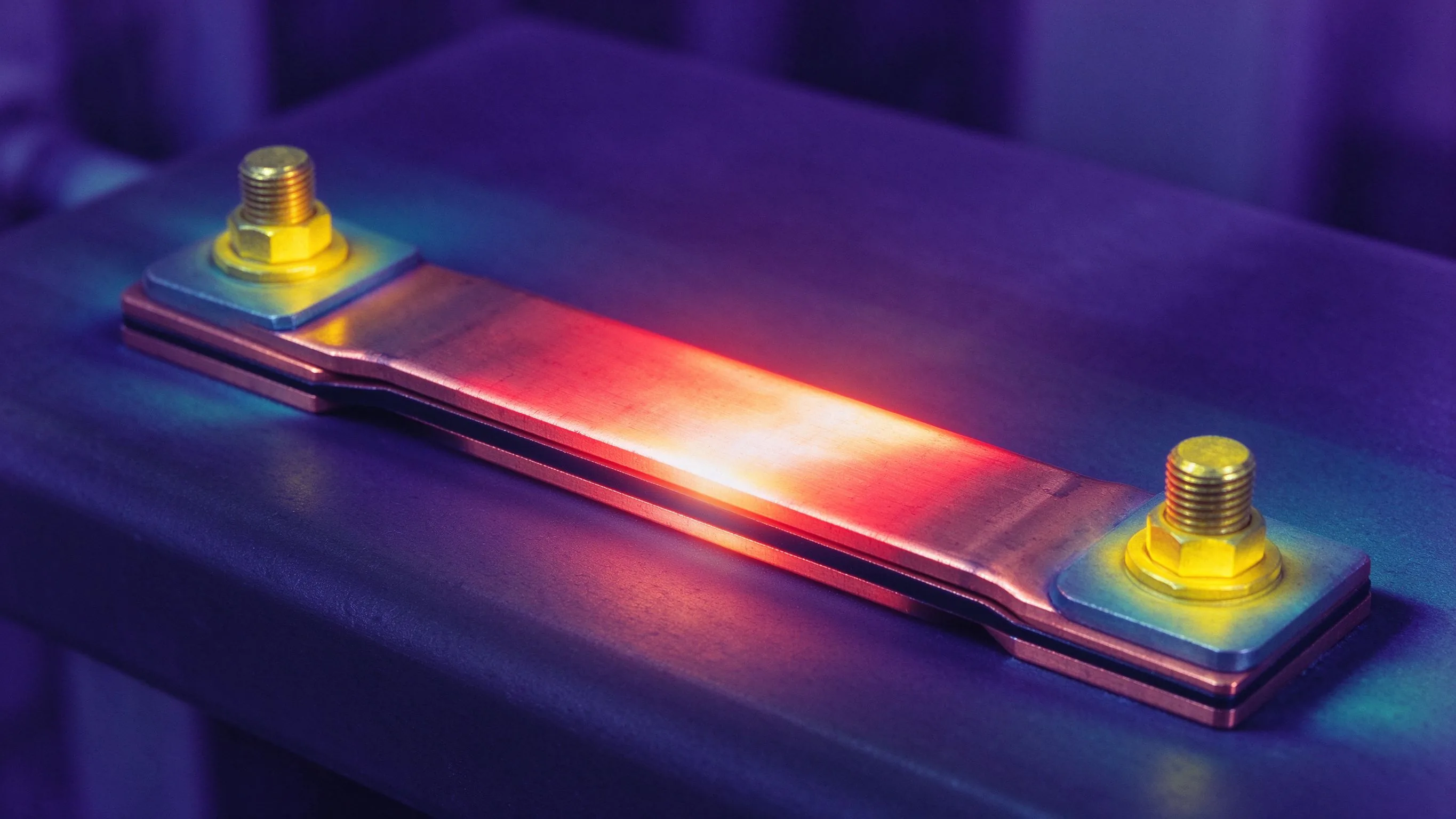
Thermal cycling degrades busbar assemblies from the inside: solder joints crack, bolt pres
Read article
A bolted busbar joint fails in one of two ways: vibration loosens it or thermal cycling fa
Read article
The plating on a busbar contact is a corrosion strategy as much as a conductivity play. Ti
Read article
Nadia Rahman is a quality and compliance engineer with 9 years in electrical-component quality systems. She manages SHANYUAN's ISO 9001 and IATF 16949 programmes, incoming and outgoing inspection, and UL/IEC compliance documentation. She holds a B.Sc. in Industrial Engineering from the Universi
Send the current profile, voltage class and terminal types — our engineers reply within one business day.