A busbar that looks correctly sized on a drawing can still overheat inside a sealed cabinet, and the failure usually starts at a joint rather than at the bar itself. Temperature-rise testing, also called the continuous-current test, converts a rated-current duty cycle into measured Kelvin rise above ambient and compares it against the limits in standards such as IEC 61439-1 for low-voltage assemblies and IEC 62271-1 for switchgear. This guide explains which standard applies, how the test object and enclosure must be prepared, how thermocouples and infrared cameras differ as evidence, where the sensors belong, when steady state is reached, and how to interpret a hotspot. It closes with the exact test-report contents a procurement or quality team should demand, so a certification dossier contains calibration records, sensor maps, steady-state data and post-test checks rather than a bare current-rating claim.
A busbar that looks correctly sized on a drawing can still overheat inside a sealed cabinet, and the failure usually starts at a joint rather than at the bar itself. Temperature-rise testing, also called the continuous-current test, converts a rated-current duty cycle into measured Kelvin rise above ambient and compares it against the limits in standards such as IEC 61439-1 for low-voltage assemblies and IEC 62271-1 for switchgear. This guide explains which standard applies, how the test object and enclosure must be prepared, how thermocouples and infrared cameras differ as evidence, where the sensors belong, when steady state is reached, and how to interpret a hotspot. It closes with the exact test-report contents a procurement or quality team should demand, so a certification dossier contains calibration records, sensor maps, steady-state data and post-test checks rather than a bare current-rating claim.
A busbar temperature-rise test, also called a continuous-current test in high-voltage switchgear practice, passes the rated continuous current through the actual conductor assembly until its temperatures stabilize, then compares the measured rise above ambient against the applicable standard limit. Its single purpose is evidence: proof that the chosen cross-section, material, plating, insulation, joints and enclosure do not overheat under the duty the equipment will see in service. A passing result protects insulation ageing, prevents softening or creep at plated joints, keeps accessible surfaces safe to touch, and supports the current rating printed on the drawing or catalogue.
This guide deliberately covers measurement, standards, instrumentation, data interpretation and the test report a purchaser should require. It complements two existing references rather than repeating them: the engineering side of heat removal and cooling architecture is covered in busbar thermal management design, while the physical basis of ampacity, resistance and current density is covered in busbar current capacity explained. A design paper can predict a rise; only a measured type test, or a defensible reference-comparison or calculation dossier, can certify it. Buyers should also remember that a temperature-rise test does not verify dielectric strength, short-circuit withstand, vibration durability or corrosion resistance; those are separate test programs, beginning with busbar insulation testing and the short-circuit methodology in the short-circuit withstand reference.
Low-voltage assemblies are governed primarily by IEC 61439-1:2020, Low-voltage switchgear and controlgear assemblies, general rules. Clause 10.10 defines how temperature-rise limits are verified, and Table 6 lists the maximum permitted rises for bare conductors, insulated conductors, external terminals and accessible enclosure surfaces. Where a busbar lives inside a switchboard, MCC, PCS cabinet or combiner box, the assembly-level clauses of IEC 61439-1 usually apply to the internal busbar as part of the assembly. Busbar trunking (busway) systems follow the companion standard IEC 61439-6, which likewise specifies thermocouple or thermometer measurement with sensors protected against air currents and radiant heat, with particular attention to conductor joints and terminals.
Medium- and high-voltage switchgear follow IEC 62271-1:2017, High-voltage switchgear and controlgear, common specifications; its continuous-current test, formerly named the temperature-rise test, is performed under sub-clause 7.5 and defines limits separately for contacts, bolted connections and external terminals according to plating and the surrounding medium (oxidizing gas, non-oxidizing gas or oil). For custom power-electronics busbars such as laminated DC-links, the governing standard may be the end-product inverter or converter standard, but designers commonly benchmark against IEC 61439-1 limits because they are widely recognized by certification bodies and purchasers. Where full testing is impractical, IEC TR 60890 provides a conservative calculation method for assemblies up to about 1600 A; it is a verification route, not a substitute for measurement on unusual or high-current designs. Maintenance-side infrared surveys follow NFPA 70B practice rather than a type-test standard, a distinction explained in Section 6.
Standard limits are stated as temperature rise in Kelvin (K) above the surrounding ambient, not as an absolute Celsius value. Under IEC 61439-1 Table 6, bare copper internal conductors are allowed up to 105 K rise; insulated conductors up to 70 K; external copper terminals up to 70 K (aluminum terminals 65 K); accessible metal enclosure surfaces 30 K; and accessible insulating surfaces 40 K. At a 40 °C design ambient, a 105 K rise corresponds to 145 °C absolute, which illustrates why the rise number must always be converted to an absolute hot-spot temperature before comparing it with material limits such as the softening point of tin.
IEC 62271-1:2017 uses tighter, plating-specific values for MV/HV contacts and connections: silver- or nickel-plated contacts and connections are limited to 75 K rise in oxidizing gas, tin-plated contacts to 50 K and tin-plated connections to 65 K, while bare copper bolted connections in oxidizing gas are limited to 60 K; external terminals follow analogous plating-based values. The reason plated surfaces carry higher allowed rise is that silver, nickel and tin prevent the rapid oxidation that raises bare-copper contact resistance; the material and trade-off discussion sits in busbar plating and corrosion guide. Insulation thermal class matters equally: a PET, Nomex or DLF film has its own maximum continuous temperature, covered in dielectric material selection guide, and the measured hot spot must stay below that class with margin. Many manufacturers, including SHANYUAN, design laminated busbars to a conservative 30 °C rise target as an engineering margin; that internal target is stricter than the standard ceiling and should not be confused with the regulatory limit.
IEC 61439-1 Clause 10.10 accepts three ways to demonstrate compliance. The first, type testing by measurement, applies rated current to the assembly or a representative part and records steady-state temperatures at prescribed points; it is the most authoritative route and the preferred one for new geometries, high-current ratings, custom laminated stacks and sealed enclosures. The second, comparison with a tested reference design, relies on thermal equivalence: same functional arrangement, comparable busbar cross-section and material, similar barriers and ventilation, and a documented loss profile. A family of repeated products can reuse a reference dossier, but every deviation in copper thickness, layer count, enclosure IP or terminal type must be justified.
The third route, assessment by calculation, uses IEC TR 60890 for assemblies generally up to 1600 A, applying conservative assumptions; industry practice adds roughly a 20% derating on current or losses and validates the model against at least one representative measurement. Simulation tools such as finite-element impedance and thermal models support design decisions, as described in FEM impedance simulation guide, but a simulation output is not a type-test certificate. The decision rule for buyers is simple: if the busbar geometry, enclosure or current rating differs materially from a previously tested reference, require a physical test; if a supplier offers only a spreadsheet estimate for a 1000 A laminated assembly in a sealed cabinet, ask for the underlying measured reference or commission the test.
Results are only valid if the test object represents the shipped product. The busbar should be mounted as it will be installed, with the actual studs, blades, welded lugs, insulating supports, covers and enclosure ventilation; testing a loose bar on an open bench ignores the convection restriction that most often causes field overheating. Bolted joints must be tightened to the specified torque with calibrated tools, because under-torque is a common hidden failure cause; the joint design principles behind that requirement are reviewed in busbar terminal connection guide. Contact faces should be clean, dry and free of oxidation or anti-oxidant grease excess, and the assembly should be inspected for burrs, missing washers and insulation damage before power is applied.
The current source must deliver the rated continuous current stably and, where several parallel conductors or layers share the current, feed them with synchronized supplies so that real current-sharing conditions are reproduced; weak or unbalanced sources can mask a hotspot on one phase. Temporary test conductors should be sized so they do not act as a strong heat sink or heat source, and the whole test bay should be free of drafts: IEC 62271-1 practice limits air velocity near the sample to 0.5 m/s. Instruments must be calibrated within their validity period: thermocouples and data loggers carry calibration certificates traceable to a national standard, and any infrared camera used as a secondary check should have its emissivity setting and focus documented. The sensor placement map, torque values, enclosure drawing revision and serial or lot number belong in the test record before the first current ramp.
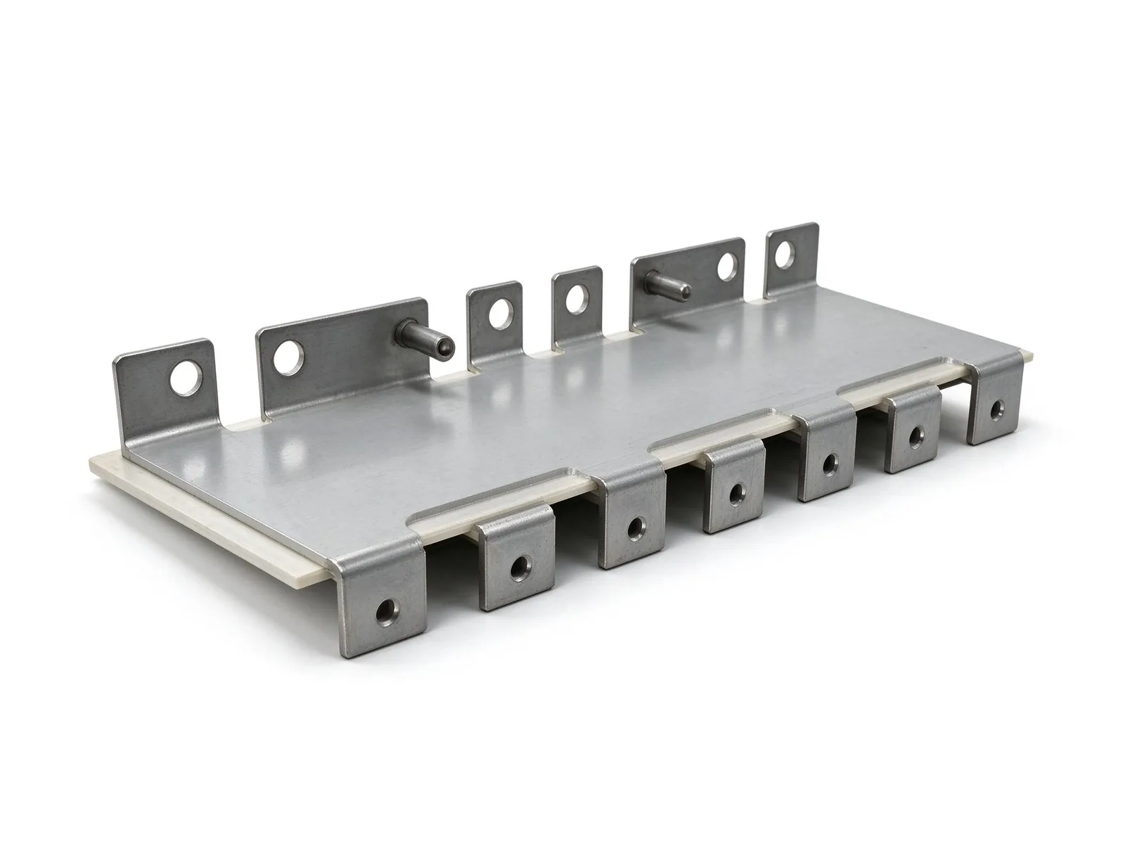
Contact measurement is the primary evidence in a type test. T-type, K-type or J-type thermocouples are bonded, welded or spring-loaded at the hottest accessible points, and a multi-channel data logger records temperature at fixed intervals; the Seebeck-effect thermocouple responds reliably over the modest temperature range of busbar tests and survives repeated cycles. Ambient is measured separately: IEC 62271-1 requires at least three thermometers or thermocouples distributed around the sample at half its height and about 1 m away, traditionally housed in small oil-filled bottles to damp air turbulence, while IEC 61439-1 keeps the average test ambient at or below 35 °C. A single room thermometer near the door is not an acceptable ambient record.
Infrared thermography is valuable but secondary for type testing. Shiny or oxidized copper surfaces have uncertain and low emissivity, and an emissivity setting error of only 0.05 can shift a quantitative reading by around 12 °C near 85 °C on oxidized copper, per ASTM E1933 calibration practice; reflections from hot components further distort the reading. IR cameras are therefore best used for trend inspection of energized equipment under normal load, consistent with NFPA 70B maintenance practice that recommends periodic infrared surveys of critical electrical equipment at meaningful load (commonly at least about 40% of rated current). For the certified test, thermocouple data govern. Contact resistance complements thermal data: a micro-ohmmeter or DLRO (ductor) measures milliohm-level resistance at each joint before energization and again after the heat run, detecting loosening or oxidation that temperature alone may miss; the measurement discipline parallels loop inductance measurement guide in requiring a defined current, lead compensation and recorded values.
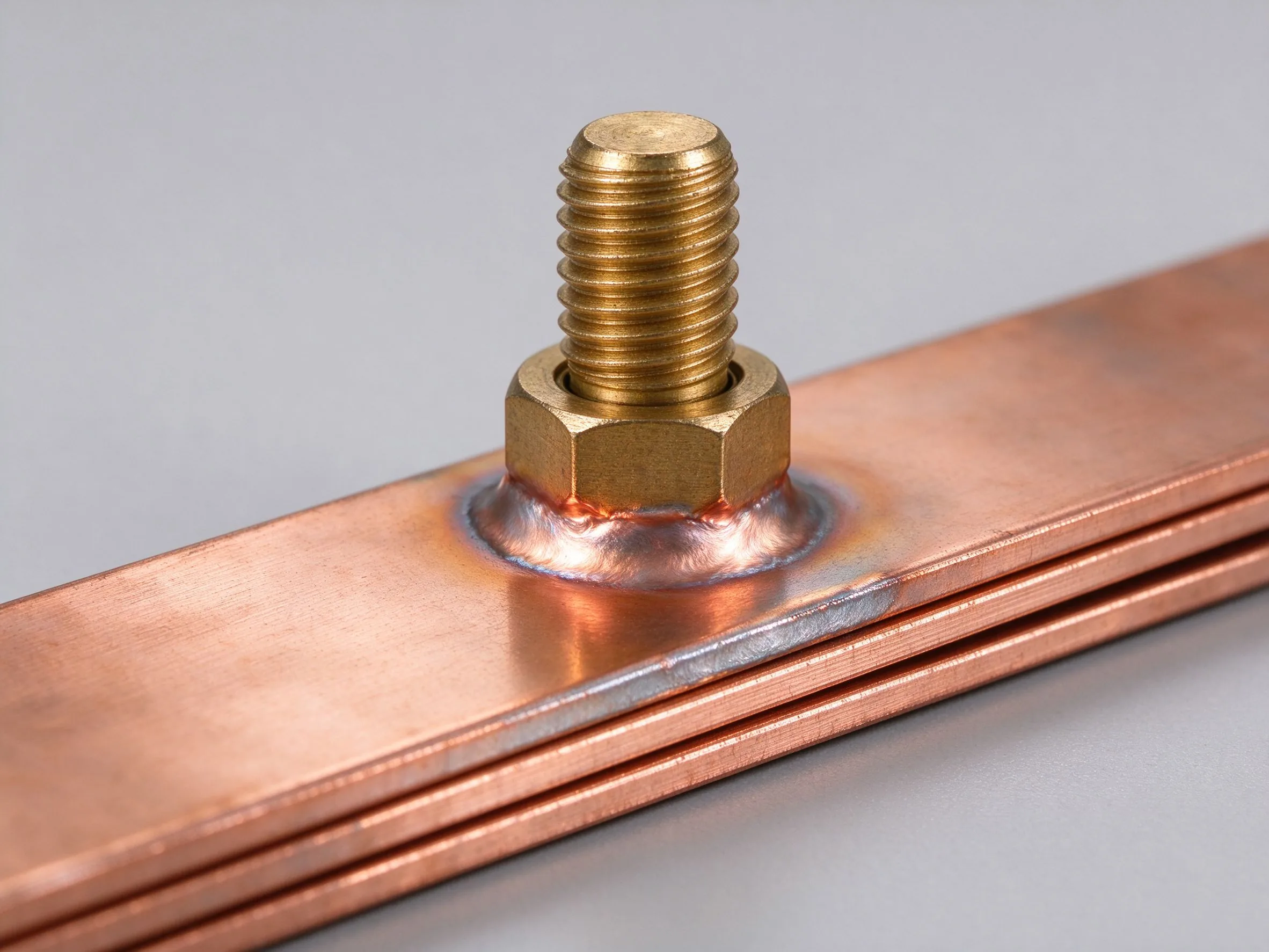
The hottest point on a busbar assembly is almost never the clean center of a straight bar; it is usually a bolted joint, crimp, flexible-to-rigid transition, stud hole or narrow neck between mounting holes. A compliant sensor map therefore covers: mid-span of every pole and every parallel path; both sides of every bolted or riveted joint; stud and blade terminal points; the root of welded or brazed connections; the highest point of flexible shunt transitions; insulating supports and standoffs that transfer heat to the bar; internal air at cabinet level; accessible outer surfaces that operators can touch; and the ambient reference points described above. When parallel conductors carry part of the rated current, each path must be instrumented because asymmetry, addressed in busbar current sharing design guide, concentrates rise on one bar.
IEC 62271-1 adds a useful quality check on temporary conductors: the rise difference between a main-circuit terminal and a point 1 m along the external test conductor must not exceed 5 K; a larger difference means the temporary wiring is drawing or dumping heat and biasing the terminal reading. Sensor attachment method should avoid artificial heat sinking: thermocouples should be small, in direct thermal contact, and insulated from radiant background, with wires routed so they do not create cooling fins. Every point needs a stable identifier on the drawing so that report tables, thermogram overlays and future reference comparisons can be aligned point by point.
A test that stops early underestimates rise because copper continues to warm after current reaches the set value. Steady state is declared when temperature change falls to a defined small band; IEC-aligned practice commonly accepts a variation below 1 to 2 K over one hour, and high-power packed assemblies often run until the drift under a shorter window, such as less than 1 °C in 30 minutes, disappears. Depending on mass, enclosure and insulation, stabilization can take 4 to 8 hours or longer, and well-equipped laboratories run overnight holds rather than extrapolating from a short ramp. The report must state the ambient range recorded during the hold, the current actually maintained, and the time at steady state; a rise number without those conditions is uninterpretable.
Ambient strategy should mirror the service duty rather than the comfort of the lab. Bench tests at 20–25 °C give conservative absolute temperatures but do not prove performance in a sealed cabinet that sees 40 °C internal air; buyers can accept a standard ambient test only if the dossier applies the correct derating for their enclosure. For equipment destined for hot climates or sun-exposed outdoor cabinets, the test plan should include a worst-case ambient note or an additional heated-enclosure run. Maintenance teams use the same steady-state idea during commissioning surveys, as outlined in busbar maintenance and troubleshooting guide: trend surveys compare successive infrared readings under similar load and ambient rather than judging a single absolute value.
DC busbars used in battery racks, DC-links and electrolyzer rectifiers are tested with a DC source at the rated continuous current, including any expected bidirectional duty if the bar charges and discharges. AC distribution busbars are tested at the rated RMS alternating current at the system frequency. The two cases are not interchangeable: DC heating comes only from Joule resistance, while AC at higher frequencies adds skin and proximity effects that raise effective resistance and rise; high-frequency power-electronics considerations are explained in skin-effect design at high frequency. Non-linear loads such as rectifiers, drives and inverters inject harmonic currents that add extra losses, so a busbar rated for a sinusoidal utility current should be derated for harmonic content, as developed in harmonic current rating guide.
Parallel paths deserve specific attention in the test plan. If two bars or several laminated layers share current, the source should maintain the sum current and each sensor set should confirm that no individual path exceeds its share; an imbalance that appears acceptable at mid-span often concentrates at a joint. Rated continuous current should be distinguished from short-time or short-circuit duty: the temperature-rise test proves sustained loading, while electrodynamic and thermal short-time performance is covered separately in the short-circuit withstand reference. For hybrid cabinets that combine an inverter DC-link with an AC output bus, the test sequence should cover each rated segment and, where possible, the simultaneous-load condition that best matches operation.
Bulk plating barely changes the rise of the copper body because tin, nickel and silver layers are thin; their decisive effect is at the joint, where they keep contact resistance stable under compression and cycling. Insulation, by contrast, traps heat: an insulated conductor commonly carries a distinct limit (70 K in IEC 61439-1 practice for insulated conductive parts) because the film or coating raises the surface temperature relative to an open bar, and the insulation's own thermal class becomes the absolute ceiling. Surface coatings and epoxy or heat-shrink layers should be described in the report with material name and thermal class; coating options are reviewed in busbar surface insulation coating guide.
After the heat run, material integrity must be checked, not assumed. Polymeric insulating supports undergo a ball-pressure check: under IEC 61439-1 practice, live-part supports are tested at 125 °C with an impression diameter limit of 2 mm, verifying that the polymer has not softened. Plated joints are examined for blistering, creep and discoloration, and flexible laminated shunts are checked at welded ends after repeated heating, the reliability logic of which mirrors the cycling program described in busbar thermal cycling reliability guide. A bar that passes the steady temperature limit but shows tin creep or insulation shrinkage at a joint has failed the release criteria and should be redesigned, not shipped with a caveat.
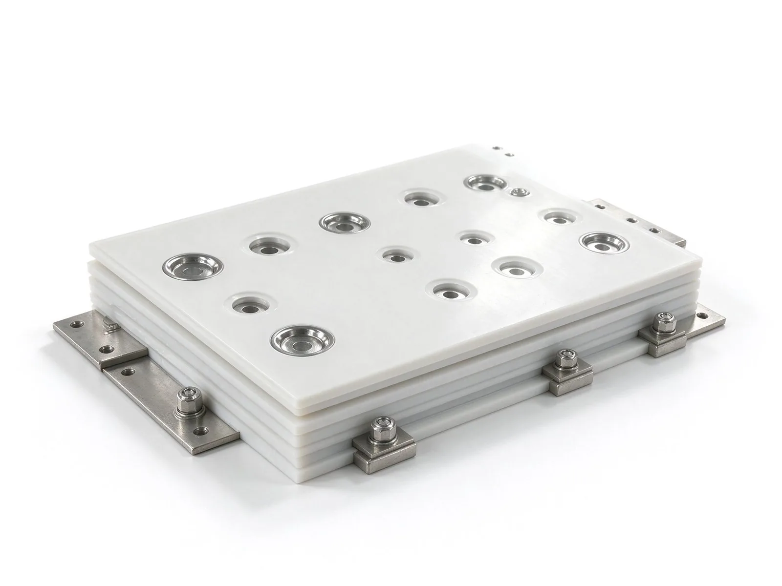
The pass/fail result is driven by the single hottest valid measurement point, not by an average across sensors. A mid-span bar at 40 K rise with one bolted joint at 78 K fails if the applicable joint limit is lower, which is why reports must list every point rather than a single headline number. Acceptance should include a safety margin below the limit: designs that sit within a few tenths of a Kelvin of the ceiling leave no room for contact ageing, manufacturing variation or a hotter future ambient, and they typically fail in the field years after certification. Repeatability matters too; a re-test after prototype changes should be performed with the same current, ambient protocol and sensor layout so that changes can be compared.
Interpreting anomalies follows a failure-mode checklist. A uniformly high rise across the bar suggests undersized cross-section or poor copper quality. A localized peak at a joint points to torque shortfall, oxidized contact faces, wrong plating, dissimilar-metal creep or excessive bolt-hole cutout. A cabinet that passes open but fails enclosed points to blocked ventilation or high internal ambient. Uneven rise among parallel phases indicates poor current sharing, and drift that worsens between pre-test and post-test resistance points signals loosening or oxidation during heating. These mechanisms are catalogued in busbar failure modes and selection guide, while the energy-loss side that correlates rise with efficiency loss is covered in voltage drop and power loss guide. The report should pair each anomaly with a root cause and a corrective action, then require re-test after redesign.
A usable type-test report answers eight questions before it reaches a certification reviewer. First, object identity: drawing number and revision, copper alloy (such as C11000), cross-section and layer count, plating type, insulation system and lot or serial identification. Second, standard and clause: the cited standard edition and the verification route (type test, reference comparison or calculation). Third, electrical conditions: rated continuous current, AC frequency or DC convention, voltage class, and any transient or duty-cycle assumptions. Fourth, enclosure and cooling: enclosure type, IP rating, ventilation orientation and mounting position. Fifth, environment: recorded ambient range, draft conditions and steady-state criterion with elapsed test time.
Sixth, evidence: the instrument list with model and calibration dates, the sensor-location diagram, raw logged curves, tabulated rise at each point, the applicable limit and the numerical margin, plus contact-resistance readings before and after the heat run. Seventh, post-test condition: visual inspection, torque verification, insulation resistance or dielectric check, and any ball-pressure or material checks. Eighth, conclusion: a clear pass/fail, signatory, and, where used, the laboratory's accreditation status; accredited independent laboratories strengthen the dossier, and utility busway specifications commonly require type tests performed by accredited bodies under the manufacturer's responsibility. Calculation dossiers under IEC TR 60890 should include assumptions, derating factors and the reference measurement used for validation. Purchaser-side scoring of the supplier should fold this document into busbar RFQ and supplier evaluation guide, while first-article evidence before series production follows the prototype workflow in quick samples and prototyping guide. Reports lacking a sensor map, steady-state record or post-test checks should be rejected as incomplete rather than accepted with verbal assurance.
The heat run ends the measurement phase, not the quality release. Standard practice after cooling down includes visual inspection for discoloration, blistering, delamination and cracked insulation; re-checking bolt torque where accessible; insulation-resistance measurement after thermal exposure; and, where required, a dielectric withstand check at the defined voltage. Dimensions and hole positions should be re-measured to detect bending or lamination expansion, and welded terminal assemblies should be examined for cracking at the heat-affected zone. If a calculation or comparison dossier was used instead of a test, the release dossier still records every assumption, the tested reference drawing and the approved equivalence argument.
SHANYUAN (Rizhao Shanyuan Electronic Components Co., Ltd.), founded in March 2012, operates a 17,200 m² plant at Taoyuan Village, Wulian Street, Rizhao, Shandong, China, exporting to more than 20 countries. Its insulated laminated busbar program covers one to six or more layers at roughly 1,000 A class, built on C11000 copper with PET, Nomex and DLF insulation, a conservative 30 °C rise design target, tin-plated contact faces, and M6 or M8 studs, blade terminals and welded terminal assemblies; the fabrication sequence behind these checks is documented in laminated busbar manufacturing process, and production release follows the design-for-manufacturing items in 2026 busbar DFM checklist. For a custom busbar project, send the rated current, enclosure sketch, expected ambient and terminal arrangement to busbar@shanyo.com for a test plan with proposed sensor points, standard clause and acceptance margin before tooling starts.
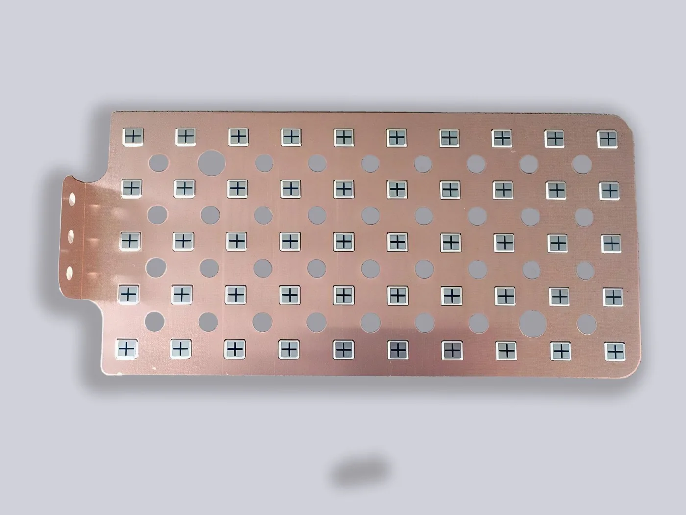
Copper busbar current rating is not a single number. It is a starting ampacity adjusted by
Read article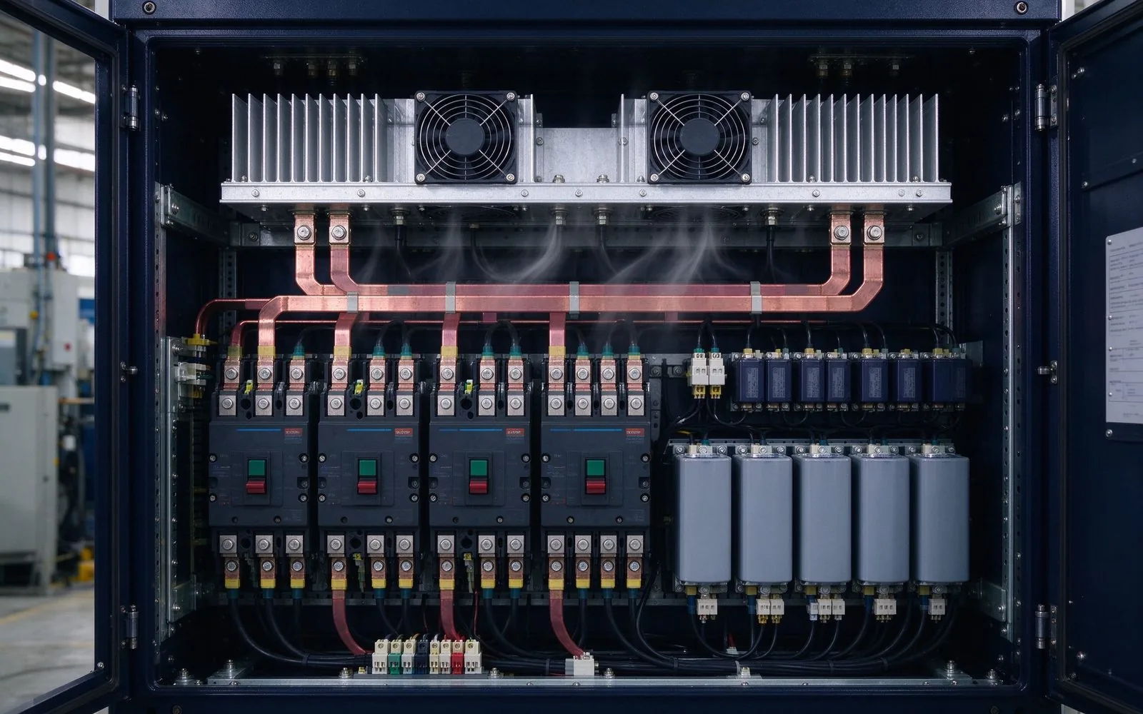
A busbar's thermal design decides its real current rating. Natural convection sheds ~50 W/
Read article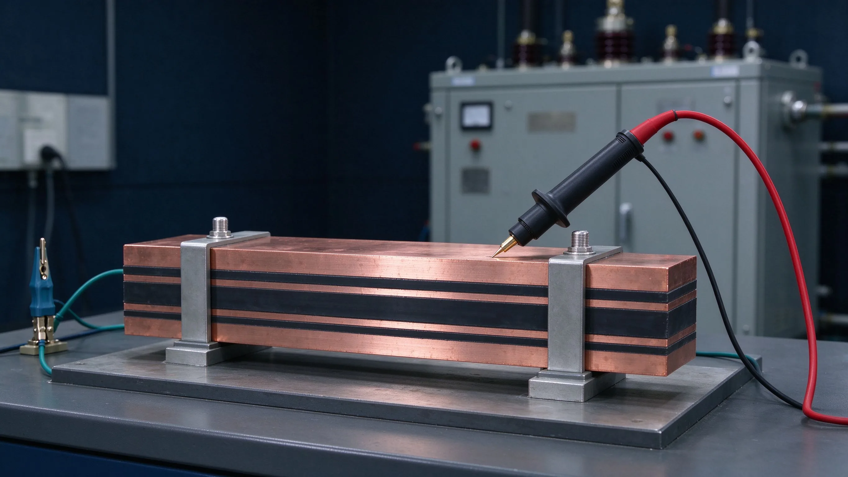
Insulation testing answers four questions: does it withstand rated voltage, does it discha
Read article
Sofia Lindqvist is a high-voltage test and partial discharge engineer with 8 years in dielectric qualification of laminated busbars. She runs IEC 60270 partial-discharge measurement, withstand-voltage and insulation diagnostics, and helped build SHANYUAN's in-house HV test lab. She holds an M.S
Send the current profile, voltage class and terminal types — our engineers reply within one business day.