A busbar that looks correct on the bench can still carry the wrong copper grade, an undersized plating layer, a cracked insulation edge or a hidden weld defect, and each problem becomes expensive once assembled into an inverter, cabinet or energy-storage rack. Quality control for laminated and stamped copper busbars is therefore a documented system rather than a final visual glance: incoming material inspection (IQC), in-process checks (IPQC), outgoing final inspection (FQC/OQC), sampling rules, and a paper trail of certificates and test records. This guide translates that system into buyer language, covering what to inspect at each stage, which standards frame the tests, which documents must accompany delivery, how defects are classified and disposed, and how to write acceptance criteria into the purchase specification. It complements the existing articles on insulation testing, fabrication tolerances and supplier evaluation by focusing on what a purchaser should demand and verify at receipt.
A busbar that looks correct on the bench can still carry the wrong copper grade, an undersized plating layer, a cracked insulation edge or a hidden weld defect, and each problem becomes expensive once assembled into an inverter, cabinet or energy-storage rack. Quality control for laminated and stamped copper busbars is therefore a documented system rather than a final visual glance: incoming material inspection (IQC), in-process checks (IPQC), outgoing final inspection (FQC/OQC), sampling rules, and a paper trail of certificates and test records. This guide translates that system into buyer language, covering what to inspect at each stage, which standards frame the tests, which documents must accompany delivery, how defects are classified and disposed, and how to write acceptance criteria into the purchase specification. It complements the existing articles on insulation testing, fabrication tolerances and supplier evaluation by focusing on what a purchaser should demand and verify at receipt.
Busbars sit between semiconductors, batteries, switchgear and loads; a conductor failure rarely stays local. Excessive resistance heats a joint, insulation breakdown can cause phase-to-phase or phase-to-earth faults, dimensional mismatch prevents assembly, and corrosion degrades contact resistance over years of service. Because busbars are often custom parts produced to a single drawing revision, quality cannot be delegated to a generic catalog standard; it must be defined on the order, evidenced by records, and checked at incoming and outgoing gates.
Procurement teams usually discover quality gaps late: during cabinet assembly, after thermal testing, or after field complaints. Moving verification earlier reduces rework cost and protects schedule. The commercial screening that precedes tooling belongs in supplier evaluation during the RFQ stage, while this article focuses on the inspection system and acceptance evidence once the supplier is selected. Both layers are necessary: a capable supplier still needs a written acceptance plan, and a strict inspection plan cannot compensate for a supplier without process discipline.
Power-critical applications such as inverters, drives and storage racks treat the busbar as a safety-relevant component, not a commodity strip. Buyers should therefore expect traceable material data, dimensional evidence, dielectric and connection checks, and a clear disposition path for nonconforming lots rather than informal promises that the parts look fine.
Shop-floor quality control commonly divides into three gates. IQC (Incoming Quality Control) inspects raw copper, insulation film, plating chemicals and purchased fasteners before production; IPQC (In-Process Quality Control) monitors cutting, bending, lamination, welding and plating operations as parts move through the line; FQC or OQC (Final/Outgoing Quality Control) performs the finished-part conformance check and packaging review before shipment. The manufacturing sequence behind these checks is described in the laminated busbar manufacturing process, which shows where each gate applies.

Buyers benefit when these gates map to the order: a first-piece sample released under IPQC becomes the reference for FQC comparison, and IQC records prevent material substitution after order confirmation. Small batches often compress the stages, but the record categories do not disappear; they are consolidated into a smaller set of inspection reports. Specifying which checks are 100% routine, which are sample-based and which are type-level evidence sets realistic expectations on both sides of the order.
Inspection evidence must arrive as controlled documents, not verbal claims. The principal records are the Certificate of Conformity (CoC) stating that delivered items meet the order specification; the material certificate or Mill Test Certificate (MTC), commonly requested as an EN 10204 Type 3.1 inspection certificate for metallic products; first-article inspection (FAI) records on the initial production batch; and dimensional, plating or dielectric test reports specific to the order. The FAI concept overlaps with the prototype approval steps covered in first-article samples and prototype validation.
EN 10204 Type 3.1 is issued by the manufacturer and validated by an authorized inspection representative independent of the manufacturing department; importantly, it is not automatically a third-party certificate. Type 3.2 adds validation by the purchaser's authorized representative or an officially designated inspector, and a separate pre-shipment audit does not by itself upgrade a Type 3.1 document to Type 3.2 (Cymber Metal procurement checklist). A usable material certificate should identify the manufacturer and plant, purchase order and line item, exact alloy designation and product form, governing standard and edition, heat, cast or production-lot identifier, actual chemistry and conductivity results, mechanical properties, test methods, covered quantity and an authorized signature.
Traceability must link every step: purchase-order item, package label, individual piece or lot number, production lot, and test-record number. Buyers should also keep document names distinct: CoC, MTC, COA, plating report and dielectric report serve different purposes and are not interchangeable. A missing record on a nonconforming lot makes root-cause analysis nearly impossible, so the purchase order should define the document pack, its issue deadline and the claim period before production starts.
Incoming inspection begins with the conductor. For laminated power busbars, standard electrolytic tough-pitch copper such as C11000 must match the drawing's alloy designation, product form, temper and governing standard; substituting a cheaper or softer grade changes conductivity, mechanical strength and spring-back after bending. IQC should verify the MTC against the physical lot markings, check chemical composition and conductivity (commonly expressed as percent IACS), and record hardness or temper where the design depends on it. Purchasing guidance on dielectrics and films complements material control in insulation material procurement guidance.
Practical incoming checks include visual condition of the stock surface (scratches, oxidation, dents), dimensional spot checks on thickness and width, and a cross-reference between delivery tags, MTC numbers and warehouse lot labels. Copper identified by a generic phrase such as electrical copper without alloy and standard edition should be treated as nonconforming until evidence is supplied. Nonconductive inputs also matter: insulation film thickness and dielectric class, adhesive compatibility, stud material and finish, and the plating bath control records should be screened at entry because downstream processes cannot correct an incompatible raw film.
Lot identity protects the customer after delivery. If a later field issue appears, traceability back to a specific heat or batch allows targeted containment rather than blanket rejection. Best practice records the IQC date, inspector, measured values, acceptance decision and any hold point, and physically segregates rejected stock so it cannot enter production by mistake.
Finished busbars must conform to the approved drawing revision, including overall length and width, thickness, hole diameters and positions, bend radius and angle, stud height, tab geometry, and the location of insulation cutouts. Instruments range from vernier calipers and micrometers for thickness and width, height gauges and fixture jigs for hole positions, and coordinate measurement or optical comparators for complex assemblies; first articles may be fully recorded while production lots sample critical dimensions. Tolerance expectations should follow established fabrication guidance in busbar fabrication tolerance recommendations rather than demanding unrealistic precision that raises cost without function.
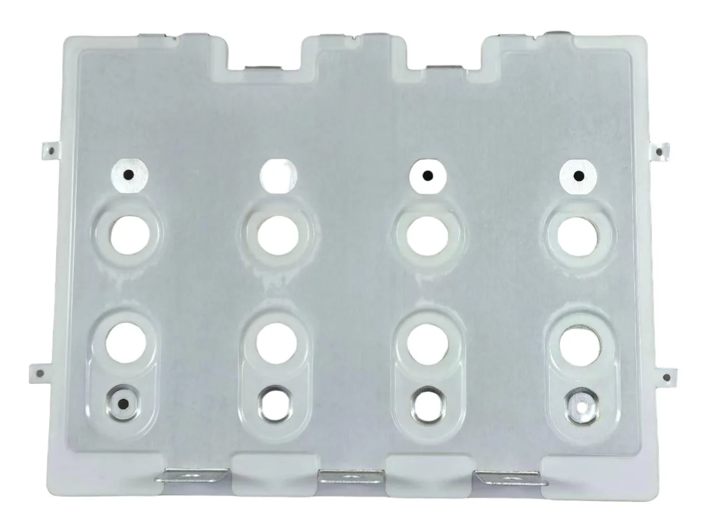
Key dimensional characteristics to list on an inspection plan include hole center distances against mating terminals, perpendicularity and flatness of contact faces (which directly affect joint resistance), minimum edge distance around drilled holes, bend-radius compliance to avoid cracking, and cut-edge condition after punching or laser cutting. Coating thickness does not appear on the dimensional report but must be accounted for when mating parts fit tightly over plated surfaces.
A simple but effective method is a controlled inspection fixture with go/no-go gauges for critical hole patterns and stack height; it repeats quickly in mass production while the CMM or detailed report remains reserved for first articles and changeovers. The buyer should define the critical-to-quality dimensions on the drawing or inspection plan so the inspector measures the features that matter electrically and mechanically, not every possible measurement. Discrepancies in dimension are usually major defects unless they are cosmetic or non-assembly related.
Common finishes on power busbars include tin plating for bolted joints, silver or nickel plating where high conductivity and corrosion resistance justify cost, and bare copper where protected by enclosure. Plating inspection combines thickness measurement, adhesion or bend tests, porosity and appearance checks, and environmental evidence where specified. Guidance on selection and failure modes appears in tin plating and corrosion protection guidance, while the insulating coating side of surface treatment is covered separately in surface insulation coating inspection considerations.
Thickness may be measured by X-ray fluorescence (XRF), coulometric strip or cross-section microscopy at defined measurement points on contact faces and high-current paths; the specification should state minimum and target values rather than an open-ended request for good plating. Appearance criteria cover uniform color, no blistering, peeling, exposed substrate, loose flakes, water stains or burnt areas, and edge coverage at cut ends. Adhesion can be screened by a bend or tape test on representative pieces, and corrosion performance may be evidenced by salt-spray or humidity chamber results agreed in advance for coastal or industrial environments.
For laminated busbars, plating must be compatible with the insulation bonding process; uneven plating on surfaces to be insulated can cause delamination or voids. Inspectors should also verify that plating is restricted where required, for example masked areas where insulation wraps over copper, and that conductive plating does not bridge insulation gaps. Record the plating lot, pretreatment condition and measured thickness on the inspection report so a later corrosion complaint can be traced to a process batch.
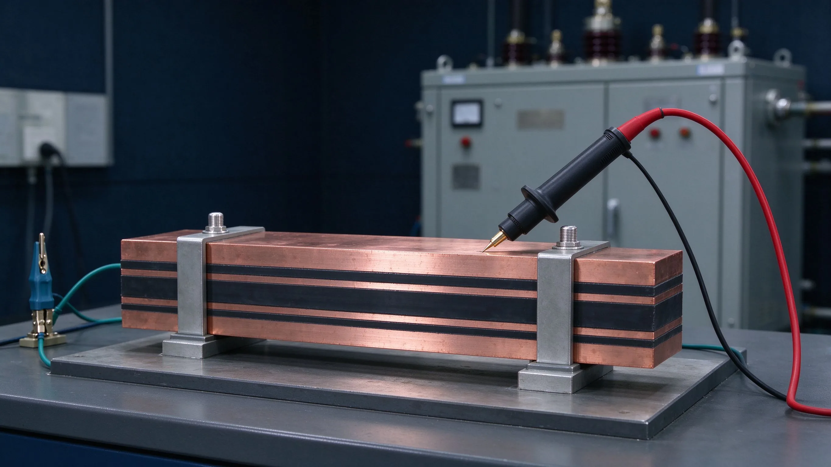
Insulated and laminated busbars require electrical insulation evidence: insulation resistance, power-frequency or DC withstand voltage on the finished assembly, and dimensional proof of creepage and clearance. The dedicated procedural discussion sits in the busbar insulation testing guide; this section positions that test inside the overall QC plan. Dielectric checks typically apply a defined test voltage between live parts and earth or between adjacent phases for a set duration, with no breakdown, flashover or excessive leakage; insulation resistance is measured with a suitable megohmmeter at the specified test voltage.
Spacing requirements should be checked against creepage and clearance design rules for the system voltage and pollution level, because surface tracking paths along insulation edges matter as much as through-film breakdown. Insulation defects to inspect include delamination, wrinkles, edge cracks, missing edge wrap, contamination on film surfaces, pinholes, and insulation that stops short of required creepage distance. PET, Nomex and DLF films differ in thermal class, dielectric strength and mechanical flexibility, so test acceptance criteria must reference the actual material specified rather than a generic insulation statement.
Not every unit receives a full type-level dielectric test in high-volume production; many suppliers perform a reduced routine hi-pot on 100% of units while retaining type-test reports for the design. The buyer should explicitly state which tests are routine on each piece, which are sampled per lot, and which design-level evidence is accepted in lieu of unit testing, and should ask whether test equipment is calibrated and how each unit's pass result is recorded. A silent insulation failure discovered after cabinet energization is a safety event, making this one of the least appropriate areas for relaxed sampling.
Electrical verification confirms that the conductor does its main job efficiently. Conductivity and current-rating principles are summarized in busbar current capacity and ampacity fundamentals; practical QC evidence includes conductor or loop resistance, millivolt drop across specified joints at a reference test current, and contact resistance at bolted or welded interfaces. Elevated resistance at a single joint localizes heat; comparing measured resistance against a design limit and a golden sample catches material substitutions, poor plating and loose or contaminated contacts before energization.
Thermal evidence ranges from routine verification of dimensions and current-path symmetry to formal temperature-rise testing. Under IEC 61439-1:2020, assemblies are verified for temperature rise (Clause 10.10), dielectric properties (Clause 10.9) and short-circuit withstand (Clause 10.11) by testing, comparison with a reference design or assessment (IEC 61439 Panels reference); published guidance notes limits such as 105 K rise for bare copper busbars, 90 K for tinned-joint busbars and 70 K for cable terminals, subject to the Rated Diversity Factor (VIOX IEC 61439 guide). Internal thermal planning should follow busbar thermal management design principles, while fault robustness relates to short-circuit withstand evidence.
For routine production, full temperature-rise tests on every batch are rarely practical; buyers commonly accept type-test reports plus resistance checks, thermal-calculation evidence and ambient derating data. What matters in the purchase specification is consistency: define the test current, measurement points, instrument resolution, ambient reference and acceptance limit, and require that results be attached to the lot record. Unrecorded pass-through testing leaves no defensible evidence during an audit or warranty claim.
Terminals and joints determine field reliability. Inspection covers welded joints, threaded M6/M8 studs, blade or tab connectors, bolt holes and mounting points. Weld inspection combines visual criteria (fusion, penetration, spatter, cracks, porosity and reinforcement shape), dimensional checks on weld size, and where justified, destructive or sectioning tests on first articles; the process choices are compared in welding and joining guidance. Studs should be checked for height, thread condition, perpendicularity, pull-out strength on approved samples and absence of cracked surrounding copper. Selection logic for the connector form appears in terminal type selection, and assembled joint best practice in bolted terminal connection practice.
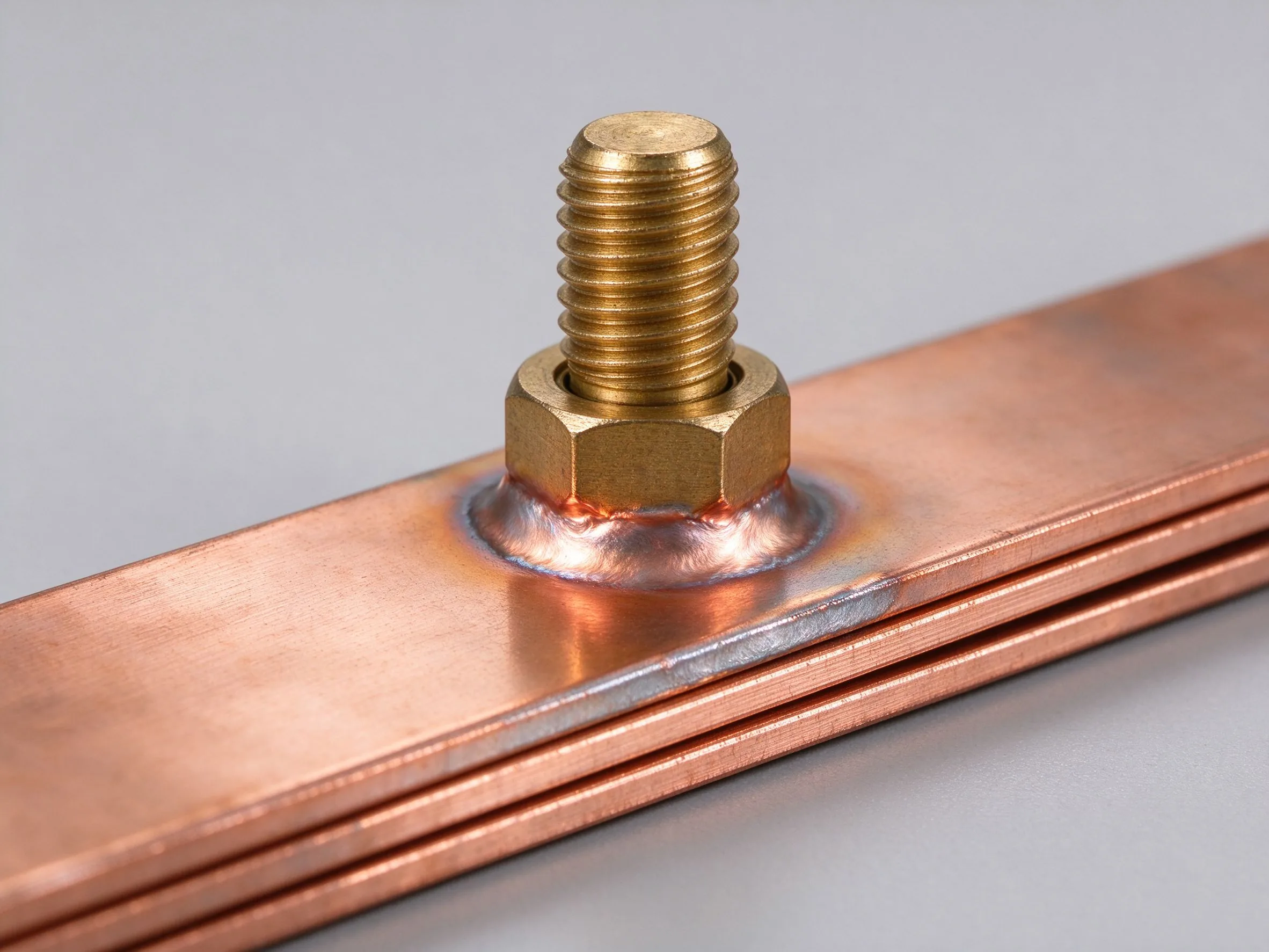
Mechanical fastening details belong to inspection too: hole size for bolt or stud hardware, washer and fastener compatibility, engagement length for threaded parts, and torque values with the specified tool class. Guidance on selecting and checking mounting hardware appears in mounting and fastener selection criteria. Torque verification on a sample of assemblies confirms that the production process can reach the required preload; under-torque invites creep and heating, over-torque can crack plated surfaces or compress insulation.
Appearance of contact faces matters because it predicts joint quality: brushed or machined surfaces should be free of burrs, insulation residue and oxide patches; insulation should be trimmed away from contact zones with clean edges. Any loose rivet, missing weld fillet or damaged thread on a power path should be classified major or critical depending on system voltage and energy level, and documented in the lot record rather than quietly repaired outside the inspection loop.
Because 100% electrical testing of every feature may be impractical, sampling provides a statistical basis for lot acceptance. ISO 2859-1 (with the equivalent ANSI/ASQ Z1.4 widely used in North American sourcing) indexes sampling plans by Acceptance Quality Limit (AQL), inspection level and lot size; it assigns a sample-size code letter, then a sample count and accept/reject numbers (ANSI Webstore, ISO 2859-1:2026 contents). General Inspection Level II is the common default; Level I reduces sample size for cheap or destructive tests, while Level III enlarges samples for new suppliers or poor quality history.
AQL values differ by defect severity. Typical commercial practice uses AQL 0 for critical defects, 2.5 for major and 4.0 for minor; for electrical hardware the major-defect level is often tightened to 1.0 or 1.5 because a failed conductor is a safety or downtime event rather than a cosmetic annoyance (Cosmo Sourcing AQL guidance based on ISO 2859-1). Critical features such as insulation withstand on safety-critical paths are usually excluded from sampling and checked 100%. The standard also defines switching rules: move from normal to tightened inspection after repeated poor lots, and reduce to reduced inspection only after a sustained good record, with discontinuation available if quality collapses.
Buyers should specify the sampling scheme in writing: inspection level, AQL per defect class, lot definition (production batch, shipment batch or supplier lot), sample selection method, and what happens to a rejected lot (100% sorting, rework, re-submission rules and cost responsibility). Sampling does not guarantee zero defects; it controls the average quality level over time, which is why records across lots, not just a single shipment, drive the supplier scorecard.
Defect classification makes acceptance decisions objective. Critical defects compromise safety, compliance or function in a fault-critical way: insulation breakdown on a live phase, a missing or cracked structural weld on a current-carrying path, wrong material conductivity that exceeds design limits, or missing mandatory markings. Major defects impair function or assembly: wrong hole pattern, insufficient plating on contact zones, nonconforming dimensions that prevent mating, or damaged threads. Minor defects are cosmetic and nonfunctional: faint surface marks, minor finish color variation or labeling imperfections that do not affect performance.
The disposition workflow for a failed result should be defined before production: quarantine the affected physical lot and preserve evidence; record a Nonconformance Report (NCR) with measured values, sample size and reference standard; determine affected quantity and probable root cause; then choose reject, sort and rework, replace, or accept by written concession. A concession must identify the exact lot, measured deviation, functional risk and approving authority, and should never be an informal chat-message approval (Cymber Metal procurement checklist on nonconforming material control).
Repeat findings trigger corrective action: tighten sampling to Level III or AQL 1.0, require process change evidence, request updated FAI after a design revision, and revisit the RFQ supplier scorecard. The same classification scheme should be shared with the supplier in the inspection plan so inspectors on both sides agree on which findings are non-negotiable. Ambiguous defect names such as surface issue without severity level lead to disputes at final inspection; a printed defect list with examples removes most of them.
Outgoing inspection confirms that the finished lot matches the approved first article and release documents. FQC typically verifies final dimensions on critical features, appearance across all visible surfaces, plating condition, insulation integrity and labeling; OQC additionally checks packing, cushioning, moisture protection, quantity against the packing list, and the correctness of shipping documents including the CoC, MTC copies, test reports and conformity declarations. Export shipments also need labels consistent with customs and packaging rules, with lot and PO references readable on each carton.
Packaging protects results achieved in the factory: bare or plated copper edges rub during transit and scratch contact faces; insulation film can crease or peel under compression; stud threads require caps or sleeves; assemblies should be separated with non-abrasive interleaving rather than loose stacked copper-to-copper contact. Moisture protection matters for humid climates, and wooden packaging should meet destination phytosanitary treatment requirements where applicable. Outgoing records should reconcile physical package IDs with packing-list and certificate numbers, closing the traceability loop from lot to delivery.
Before release, the responsible inspector signs the lot record, and the document pack should be assembled in a consistent order so the customer's receiving team can audit quickly: PO and drawing revision, CoC, material certificate, FAI or dimensional report, plating and insulation test records, and NCR or concession records if any. A clean release without paperwork delays internal qualification even when parts are physically sound.
The strongest QC agreement lives in the purchase specification and PO rather than in emails. Minimum elements include the applicable drawing revision and standard edition; critical dimensions with tolerances; material alloy and condition; finish, plating thickness and surface treatment requirements; insulation material, thickness and dielectric acceptance criteria; electrical tests (resistance, hi-pot or insulation resistance) with voltage, duration and limits; mechanical tests and torque values; sampling plan (ISO 2859-1 level and AQL by defect class); required document pack; witness or hold points; retest and resampling rules; NCR and concession procedure; packaging and labeling; and the claim or acceptance period. Design feasibility should be screened before commitment through the DFM checklist, because an unmanufacturable drawing guarantees inspection disputes.
Separate type-level evidence from routine lot evidence. Design-level items such as thermal rating, short-circuit strength or full dielectric type test can be supplied as approved reports from a qualified design, while lot-level items such as dimensions, plating thickness, labeling and contact-surface condition are checked per shipment. State whether third-party inspection (for example at loading) is required, and clarify that such a visit supplements rather than replaces supplier certificates.
Good specifications define instruments and reference standards where safety depends on measurement: test voltage and equipment class for dielectric checks, micrometer or XRF method for plating, torque tool accuracy for studs, and traceability of calibration. The acceptance plan should also be realistic about MOQ-driven trade-offs: very small batches may use 100% critical checks instead of statistical sampling, with the plan written accordingly. Finally, include a revision-control rule: drawing or material changes trigger a new FAI and documentation update rather than automatic shipment under the old records.
Rizhao Shanyuan Electronic Components Co., Ltd. (SHANYUAN), established in March 2012 and operating a 17,200 m2 facility in Taoyuan Village, Wulian Street, Rizhao, Shandong, China, exports laminated busbars to more than 20 countries. The product scope covers insulated laminated busbars from 1 to 6 plus layers rated around 1000 A on C11000 copper, with PET, Nomex or DLF insulation, a conservative 30-degree-Celsius temperature-rise design basis, tin-plated contact regions, and M6/M8 studs, blade terminals or welded terminal options.
On this product range, inspection planning follows the stages described above: incoming review of copper and insulation lots against the order specification; in-process checks of cutting, forming, lamination and plating operations against the approved first article; and final checks of dimensions, finish, insulation condition and terminal geometry before packing. Delivered records are organized to the purchase order and production lot, with material and process documentation traceable to the shipped quantity, and custom specifications agreed project by project on the drawing and inspection plan. Technical and inspection-plan discussions can be opened with engineering teams at busbar@shanyo.com, attaching the drawing, expected system voltage, current rating and required test items.
This section describes the inspection framework and standard product characteristics rather than claiming specific certifications or customer programs; formal compliance marks, test standards and report formats are agreed for each project according to the customer's destination market and application, so the buyer and supplier share one acceptance record before production begins.
Insulation testing answers four questions: does it withstand rated voltage, does it discha
Read article
A busbar's reliability is decided in the first 2 mm of the drawing: hole position, bend an
Read article
Buying a laminated busbar is not like buying a standard connector. The part is custom, the
Read article
Nadia Rahman is a quality and compliance engineer with 9 years in electrical-component quality systems. She manages SHANYUAN's ISO 9001 and IATF 16949 programmes, incoming and outgoing inspection, and UL/IEC compliance documentation. She holds a B.Sc. in Industrial Engineering from the Universi
Send the current profile, voltage class and terminal types — our engineers reply within one business day.