The railway traction converter is going through its semiconductor transition. Global Market Insights projects SiC traction converters rising from USD 0.33 billion to USD 0.61 billion over the forecast period at a 7.06% CAGR, while IGBT converters remain dominant, growing from USD 2.19 billion in 2026 to USD 3.81 billion by 2035 at 6.32% CAGR (Global Market Insights, August 2026). A 500-kVA full-SiC active-neutral-point-clamped prototype has already demonstrated 98.7% efficiency under rated conditions. For the DC-link busbar that couples the converter's capacitor bank to its switching devices, the transition changes everything - switching speed, voltage slew, vibration environment and qualification.
The railway traction converter is going through its semiconductor transition. Global Market Insights projects SiC traction converters rising from USD 0.33 billion to USD 0.61 billion over the forecast period at a 7.06% CAGR, while IGBT converters remain dominant, growing from USD 2.19 billion in 2026 to USD 3.81 billion by 2035 at 6.32% CAGR (Global Market Insights, August 2026). A 500-kVA full-SiC active-neutral-point-clamped prototype has already demonstrated 98.7% efficiency under rated conditions. For the DC-link busbar that couples the converter's capacitor bank to its switching devices, the transition changes everything - switching speed, voltage slew, vibration environment and qualification.
Rail is the rare industry where power electronics content is still growing per vehicle. China's rapid expansion of high-speed rail and urban transit has made it the largest market for SiC VVVF inverters globally, with the market sized at USD 4.5 billion in 2024 and projected to grow from USD 5.0 billion in 2025 to USD 8.5 billion by 2033 at about 8.9% CAGR (Verified Market Reports, May 2026). On the supply side, CRRC Corporation (via Zhuzhou CRRC Times Electric) holds more than 60% of the domestic urban-rail traction converter market as of 2025 and is active in overseas projects (PW Consulting, June 2026).
For component suppliers, the consequence is a qualification-driven market: traction programs qualify busbar suppliers against rail standards, and the order volumes follow fleet programmes, not catalogues. The same qualification logic shapes every supplier decision in the traction supply chain, from semiconductors to the DC-link busbar itself.
SiC MOSFETs switch an order of magnitude faster than the IGBTs they replace, and the traction converter's DC-link busbar is the component that must keep the commutation loop small enough for that speed. A large loop inductance means voltage overshoot at turn-off proportional to L x di/dt; with SiC's di/dt, even a few tens of nanohenries of excess inductance produce destructive spikes across the devices.
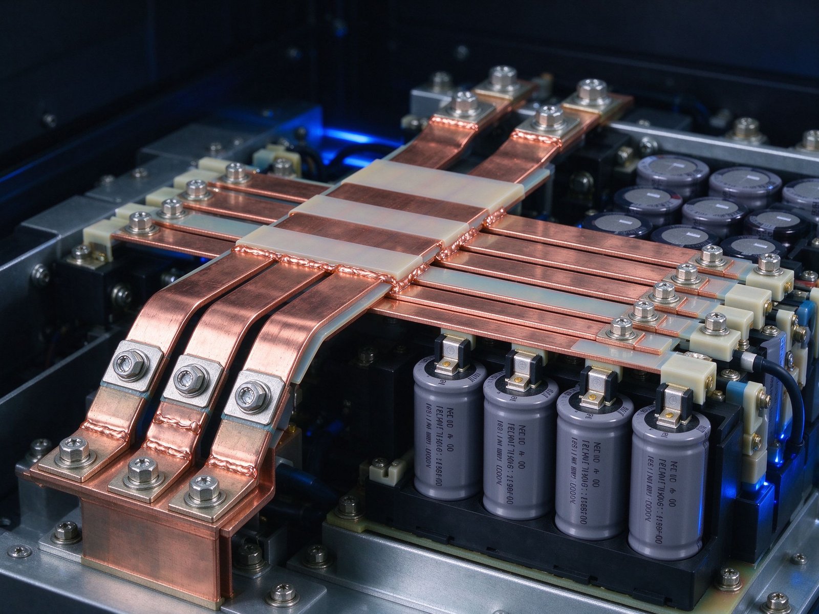
The laminated busbar is the standard answer because it cancels loop inductance by construction - forward and return currents in close parallel planes - rather than by careful cable routing, which cannot be repeated unit to unit on a production vehicle. The high-frequency side of that same story - skin and proximity losses at SiC switching speeds - is covered in our skin effect design guide.
The 500-kVA full-SiC active-neutral-point-clamped prototype achieving 98.7% efficiency under rated conditions sets the efficiency bar for traction programs (Global Market Insights, August 2026). The last tenths of a percent come from conduction and switching losses, but also from the DC-link: a busbar with measurable AC resistance at switching frequency wastes watts that show up in the efficiency number. Laminate thickness relative to skin depth, plating quality and terminal contact resistance all contribute.
At 98.7%, every milliohm of joint resistance and every micrometre of plating variation is visible in the test report. That is why traction-grade busbars are built to drawing, inspected for plating and pull-out, and supplied with records - not shipped as generic stock.
Efficiency at the 98.7% level also changes the test culture. At that margin, the difference between 98.7% and 98.9% is visible in the converter's thermal and energy figures, and the DC-link's contribution - its AC resistance at the switching frequency, its joint resistance at every bolted interface, its plating quality on the current-carrying surfaces - is a line item that the test report now records separately. The busbar supplier's plating thickness control and joint resistance documentation stop being paperwork and become part of the efficiency budget.
The same precision applies to the dielectric and PD margin. A traction converter at 1.5-3 kV DC with SiC dv/dt in the tens of kV per microsecond pushes the insulation system hard; partial-discharge testing on the busbar at the working voltage and a margin above it is the evidence the OEM carries into the vehicle's electrical safety file. The test protocol - PD inception voltage, discharge magnitude, the margin to the working voltage - follows the practice described in our partial discharge guide.
Traction DC-links operate at 1.5 kV DC on metro systems, 1.8-3 kV on main-line and freight electric locomotives, with transient peaks well beyond. Creepage and clearance on the busbar must follow rail practice, and the dielectric system must survive the service environment: temperature cycling, humidity, contamination from brake dust and the cleaning agents used in depots.
SHANYUAN builds traction DC-link busbars on PET, Nomex or epoxy DLF dielectric with edge sealing to control creepage, and terminal plating (tin, silver or nickel) selected for the connection duty. The creepage and clearance guide documents the sizing rules we apply.
Rail equipment is qualified to IEC 61373, whose random vibration spectra for bogie-mounted and body-mounted equipment are far more demanding than a stationary industrial cabinet. The busbar must hold its bolted joints, its dielectric edges and its terminal connections through millions of vibration cycles, at temperature, for decades.
Laminated construction is vibration-friendly by design - bonded layers move as one body, and the flat laminate face mounts to the converter frame across a large area. The bolted terminal connections are the vulnerable points, and they follow the same preload, washer and thermal-cycling discipline covered in our connection guide and detailed further in the vibration and bolted joint design guide.
The vibration story has a fleet-level dimension. A metro fleet of 50 trains runs each converter through roughly 1.5 million vibration cycles per decade in service; the busbar's bolted joints are the only parts of the DC-link that move at all, and their torque behaviour is the one variable the maintainer can act on. That is why the maintenance plan includes torque re-check intervals, why the drawing states the values, and why the qualification evidence includes vibration testing with post-test torque measurement rather than a pass on visual inspection alone.
For the design file, the vibration input is not a single number but a spectrum per mounting position - bogie-mounted, body-mounted and roof-mounted equipment see different IEC 61373 categories, and the busbar's mounting stiffness changes its response. The practical output is a mounting layout with enough fastening points to keep the first natural frequency above the dominant excitation band, and a bolted joint design whose preload window survives the spectrum with margin. Both are documented outputs of the mechanical design, not field improvisations.
A traction converter packs the capacitor bank, the power stack and the DC-link into a cabinet with centimetres to spare. The busbar is often the largest single conductor in the assembly, and its footprint directly constrains the capacitor bank layout. Laminated stacks with integrated capacitor mounting help here: the laminate can carry threaded studs or welded inserts for capacitor terminations, collapsing the commutation loop to the capacitor-to-device spacing.
Our capacitor bank busbars and IGBT module busbar sets are the two families that traction programs typically start from.
The active-NPC and 3-level topologies favoured in traction need more than two conductor planes. A three-level NPC converter's DC-link busbar carries positive, neutral and negative potentials, and the stray inductance between each pair of planes appears in the corresponding commutation loop (IEEE, 2014). The neutral plane in particular must be a controlled geometry - a 'split plate' whose position sets the balance between the upper and lower commutation loops.
Designing a three-level laminated busbar is a 3D electromagnetic exercise, not a 2D layout. The layer stack order, inter-plane dielectric thickness and terminal positions all trade against each other, which is why traction programs validate the stack in FEM before cutting copper. Our power electronics laminated busbar family covers the 3-level geometry.
Rail equipment carries fire-safety requirements that industrial busbars do not: EN 45545 fire behaviour classes for materials, smoke and toxicity limits, and flammability requirements for insulations and cable systems. The dielectric films and edge materials in a traction busbar must be selected and documented against these classes, and the material certificate must follow the part.
This is a qualification item, not a design detail. SHANYUAN supports traction programs with material declarations against the applicable EN 45545 hazard levels and with the inspection records that auditors expect.
Traction OEMs qualify suppliers the way aerospace does: first articles, dimensional reports, material certificates, insulation and PD testing, temperature-rise testing at rated current, and vibration or thermal-cycle evidence where required. The busbar supplier's factory must be able to produce all of it, on schedule, in the project's language.
Our quality page describes the factory's inspection setup; the practical point for program managers is that a traction-grade busbar is a documented, serialised part, not a shelf item.
Beyond new fleets, the retrofit market is large: legacy IGBT converters being upgraded with SiC modules, and metro fleets getting efficiency retrofits to cut energy cost. Retrofits keep the vehicle platform and often the cabinet, but the DC-link busbar must be redesigned for the new devices' di/dt and current profile. A laminated busbar with measured geometry can be reverse-specified from the new module datasheets and the existing cabinet envelope.
This is where a factory-direct supplier with an engineering desk adds value - the retrofit busbar is a custom part, and the drawing work happens against the real cabinet, not a catalogue.
China's urban-rail investment continues through its '15th Five-Year' planning period with an explicit digital and electrification agenda (China State Railway Group coverage, March 2026), and overseas metro and high-speed programs keep ordering from Chinese traction suppliers. Each program is a multi-year, multi-fleet commitment, which makes early supplier qualification the gating item for busbar programs. The suppliers that can hold rail-grade documentation, vibration evidence and delivery schedules win the platforms.
The input list is short but unforgiving: DC bus voltage and transient peak; peak and RMS current including regenerative braking; switching frequency and device type (SiC or IGBT, and the topology); cabinet envelope and capacitor layout; vibration class per IEC 61373; fire class per EN 45545; and terminal scheme (blade, stud, welded). Send those to SHANYUAN's engineering desk and the layer stack, dielectric set and terminal layout come back as a documented design with a factory-direct quote. Start from our custom busbars page or the rail application page.
The specification conversation usually ends with the commercial question, and it is worth answering here: a traction-grade laminated busbar is priced on engineering content, not copper weight. The layer stack, the dielectric system, the terminal scheme, the documentation and the qualification evidence are the product; the copper is the raw material. Programs that tender on weight find out at the qualification round why the engineering content is priced as it is - and why the cheapest first article is rarely the cheapest fleet.
Modern metro and light-rail operation is regenerative: the traction converter pushes energy back to the DC catenary or third rail during braking, and the DC-link sees current in both directions with a demanding duty cycle. The busbar carries the same RMS current in either direction, but the transient behaviour differs - the regenerative pulse has a steep rise when the inverter re-synchronises with the line, and the commutation loop must handle both directions of di/dt.
Laminated construction is direction-agnostic by design - the loop inductance is the same whether the current flows out to the motor or back to the line - which is a genuine advantage over cable layouts whose loop geometry differs by current path. The design documentation should still state the worst-case pulse for both directions.
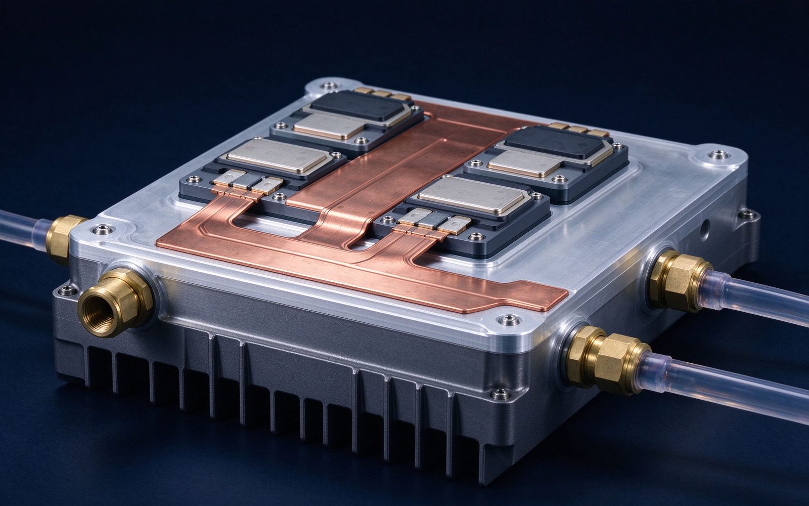
As traction converters densify, the DC-link busbar increasingly mounts on a liquid-cooled cold plate shared with the power stack. The laminated stack's flat face is the thermal interface: a thin thermal pad or direct bonding couples the laminate to the plate, and the rise calculation uses the coolant inlet temperature rather than ambient. This is where the busbar and the converter's cooling system become one design - the laminate footprint, the plate layout and the flow path are frozen together.
SHANYUAN delivers busbars with integrated cold-plate mounting in traction and industrial programs, and the thermal management guide gives the calculation method.
Rail programs track every safety-relevant component. The DC-link busbar carries serialisation in practice even where not formally required: material certificate, plating batch, dimensional report, insulation and PD test record, and the torque values of its terminal joints. When a fleet-level issue appears - say, a vibration anomaly at a specific joint - the serialised record tells the engineering team exactly which parts share the suspect batch.
Suppliers should therefore treat the paperwork as part of the part. At SHANYUAN, every custom busbar ships with its inspection file, and the file survives the program: it is the record the maintainer pulls during a mid-life overhaul.
A typical metro traction converter runs a 1.5 kV DC-link with peak current around 1.2-1.5 kA per switch position. A laminated DC-link for such a unit uses two or three copper layers of 2-3 mm, PET or Nomex dielectric, silver-plated stud terminals on the capacitor side, and a loop inductance target in the 10-20 nH range to keep SiC turn-off overshoot inside the device SOA. The laminate is mounted on the converter's cold plate, and the rise at rated RMS current is verified at FAT.
The three variables that dominate the design - layer count, inter-plane film thickness and terminal position - are exactly the three that the FEM study (see our impedance simulation guide) optimises before copper is cut.
Rail programs buy in fleets, and fleets demand standardisation. The DC-link busbar's geometry is defined once for the platform and reproduced for every vehicle in the order - which is precisely why the design must be frozen against simulation and prototypes before the fleet order, and why the manufacturing process must hold the geometry within the drawing tolerance fleet after fleet. Interoperability adds a second layer: if the same converter platform is delivered to multiple operators with different maintenance cultures, the busbar documentation (torque values, inspection intervals, spare-parts drawing) must speak the operator's language and survive the handover.
For suppliers this means the busbar is a platform component with a configuration record, not a one-off. The drawing, the test evidence and the maintenance instructions move with the fleet, and the serialisation practice described earlier is what makes fleet-level field data useful.
What a traction OEM actually checks when qualifying a busbar supplier: the manufacturing process (lamination press, plating line, inspection stations); the documentation system (material certs, dimensional reports, insulation and PD records, torque records); the test capability (temperature-rise test at rated current, impedance or DPT evidence, vibration evidence); the failure history on comparable programs; and the engineering depth available during the program. Each item maps to a deliverable the supplier either produces routinely or cannot.
The checklist is worth taking seriously because it is the same checklist the OEM's own customer - the operator or the regulator - applies to the vehicle. A supplier that cannot produce the evidence cannot ride on the OEM's qualification. SHANYUAN's quality page documents the factory-side chain that supports these submissions.
One more qualification item is worth adding because it is the one most often skipped: the first-article sign-off against the drawing's critical dimensions. The layer stack height, the inter-plane film thickness, the terminal positions and the plating thickness on contact faces are the variables the electromagnetic and thermal models are sensitive to, and the first article is the moment the model meets the metal. A dimensional report that matches the drawing within tolerance is the bridge between the FEM study and the fleet; a report that drifts is the first warning that the process or the model is wrong.
Send the current profile, voltage class and terminal types — our engineers reply within one business day.
