The Fusion Industry Association counted $4.48 billion in private fusion capital over the 12 months to July 2026, across 56 active companies and a workforce north of 16,000. Behind the plasma headlines sits a quieter procurement wave: kA-class power converters, capacitor banks, and the laminated copper busbars that connect them. SPARC's 18 D-shaped REBCO magnets, each wound with a 31.25 kA superconductor, now sit in an assembly hall; ITER's central solenoid modules ramp to 46 kA. These pulses ask copper a question that steady-state ampacity never does: what happens when 50 kA rises in a fraction of a millisecond?
The Fusion Industry Association counted $4.48 billion in private fusion capital over the 12 months to July 2026, across 56 active companies and a workforce north of 16,000. Behind the plasma headlines sits a quieter procurement wave: kA-class power converters, capacitor banks, and the laminated copper busbars that connect them. SPARC's 18 D-shaped REBCO magnets, each wound with a 31.25 kA superconductor, now sit in an assembly hall; ITER's central solenoid modules ramp to 46 kA. These pulses ask copper a question that steady-state ampacity never does: what happens when 50 kA rises in a fraction of a millisecond?
This page is an annual rolling data page: the 2026 edition, refreshed once a year as new market data is published.
The Fusion Industry Association's 2026 Global Fusion Industry Report counts 56 active fusion companies worldwide and $4.48 billion in private capital raised over the 12 months to July 2026, bringing cumulative industry funding to roughly $14.24 billion. The FIA's 2026 Supply Chain Report, surveying 25 private developers and 67 suppliers, found supply-chain spending grew 24% from $434 million in 2024 to $538 million in 2025, with another 27% growth projected.
The devices driving this spend are concrete. Commonwealth Fusion Systems installed the first of 18 D-shaped high-temperature-superconducting magnets for SPARC in early 2026; each magnet weighs about 24 tonnes, generates a 20 T winding pack and carries a 31.25 kA superconductor current. Helion's seventh-generation Polaris machine has demonstrated measurable deuterium-tritium fusion at plasma temperatures around 150 million degrees Celsius, and Helion closed a $465 million Series G in June 2026 at a $15.5 billion valuation. TAE Technologies streamlined its research machine Norman into Norm, roughly half the hardware count, and is now building toward Copernicus for Q>1. ITER, meanwhile, remains the reference point: 15 MA plasma at 5.3 T toroidal field, 500 MW fusion power, and a central solenoid that pre-magnetizes six modules to 40 kA each.
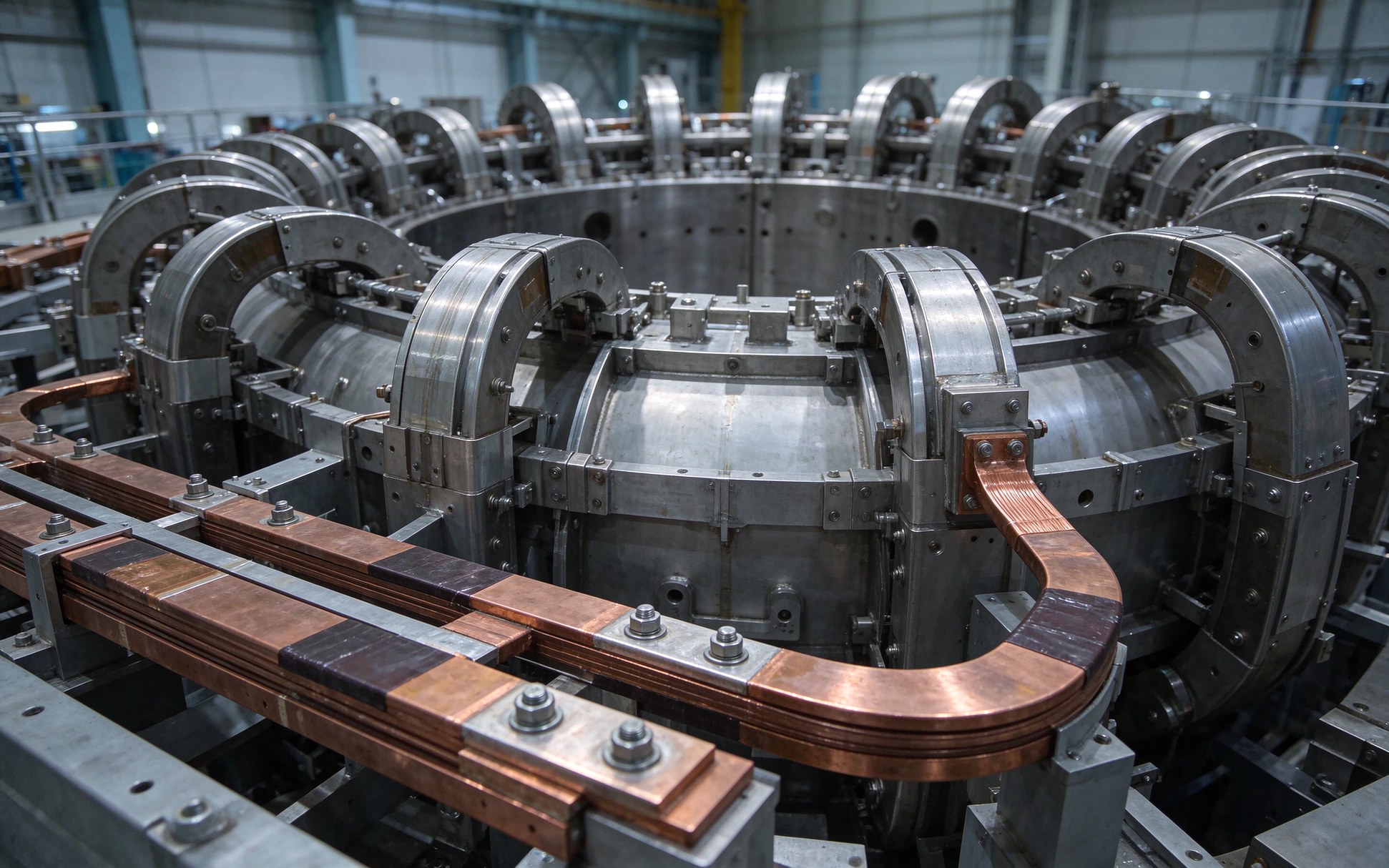
Most commentary stops at plasma temperature. Engineering buyers see the same milestone differently: every ampere of that 31.25 kA has to flow through a bus, a switch, a terminal. The nuclear-adjacent power story for small modular reactors, covered in our piece on behind-the-meter SMR power purchase structures, shares the same converter-class busbar demand as fusion. The broader electrification push, from industrial heat pumps to electrolyzers, is catalogued in the industrial heat electrification busbar round-up. Fusion sits at the fast-transient end of that same supply chain.
Today's experimental fusion devices run in pulses. The plasma lasts seconds to minutes, then the machine recharges. ITER's central solenoid pre-magnetization phase alone runs for tens of seconds while each of six modules climbs to 40 kA, followed by ramp-up, flat-top and dump. SPARC's HTS magnets hold 31.25 kA steadily, but plasma initiation, vertical displacement events and fast shutdowns are transient events superimposed on that steady bias.
A laminated busbar rated "1000 A continuous at 30 K rise" — the table most catalogues sell — describes a cooling problem. A pulse busbar describes three separate problems at once: instantaneous copper heating during the shot, magnetic force that slams conductors apart every pulse, and voltage spikes from current commutation. If you size the part from a steady-state ampacity table, you will over-specify copper cross-section for cooling while still under-specifying terminal bolts for peak force.
This is why the product category itself has shifted. A standard laminated busbar built for inverter DC-link duty already carries a lot of the required physics — overlapping conductors, thin dielectric, low loop area — but the pulse envelope pushes the design window into a different regime. The starting reference for any engineer new to this is the ampacity chart by copper cross-section, which separates continuous thermal current from the pulse corrections you still have to calculate on top.
A current-carrying bar generates magnetic field proportional to I. If the return path is a separate bar routed elsewhere, the loop area enclosed between go and return encloses magnetic flux, and that flux translates into loop inductance L. A laminated busbar stacks the positive and negative conductors face-to-face with a thin dielectric — PET, Nomex or double-side fluoropolymer — between them. The opposing currents cancel field in the shared gap, and the loop area collapses to the physical thickness of the laminate.
For a rectangular pair of width w, dielectric gap d and active length L, a useful first-order estimate is L_loop ≈ μ0 · d · L / w. Plug in w = 100 mm, d = 0.5 mm, L = 0.5 m: L ≈ 4π×10-7 × 0.0005 × 0.5 / 0.1 = 3.1 nH. Add end turns, terminal hardware and realistic bow in the laminate, and a total loop inductance of 8 to 15 nH per run is what engineering teams actually accept. A cable or bus duct of the same length typically lands at 100 to 300 nH — a 10× penalty for the same copper.
The starting point for anyone designing around this is the low-inductance design resource page, which covers the geometry rules. The measurement side is equally important: the loop inductance measurement guide explains how to extract nH values from T-equivalent impedance sweeps instead of trusting a vendor claim.
Start from the inductor law V = L · di/dt. The slow plasma ramp is dominated by the magnet coil itself, not the bus. A tokamak toroidal-field circuit carries inductance on the order of 1 mH; applying 1 kV across that loop gives di/dt ≈ 1 kA/ms. The busbar's own 10 nH is 0.001% of that total, invisible for ramp timing. This is the regime where many engineers conclude busbar inductance doesn't matter.
Fast commutation tells a different story. When a crowbar switch opens, an IGBT stack commutates off, or a plasma disruption dumps current, the external loop can see di/dt of 10 to 50 kA per microsecond. At 50 kA/µs (5×10¹⁰ A/s) and L = 10 nH, the voltage spike on the busbar is V = 10×10-9 × 5×1010 = 500 V. At 20 nH, that spike doubles to 1,000 V. At 200 nH (a cable run of similar length), it hits 10 kV.
That spike lands across the dielectric edge and the terminal gap. It is the difference between an insulation system that survives for a decade and one that punctures on the first disruption. This is why loop inductance in nH is not a marketing number — it is a fast-transient voltage budget. The FEM impedance simulation guide walks through the same calculation with finite-element models that capture end-turn effects a hand formula misses.
Take a 0.5 m wide laminated run with DC resistance R = 1 mΩ (0.001 Ω). The pulse envelope: peak current Ipeak = 50 kA, pulse duration τ = 2 ms, repetition period T = 10 s (one shot every 10 seconds, typical for today's experimental devices).
During the pulse, instantaneous loss is Ppeak = I2R = (50,000)2 × 0.001 = 2.5 MW. RMS current over the period is Irms = Ipeak × √(τ/T) = 50,000 × √(0.002/10) = 707 A. Average loss over the cycle is Pavg = Irms2 × R = 500 W. The peak-to-average ratio is 5,000:1.
The 2.5 MW pulse heats the copper locally. With the thermal mass of 0.5 m² of laminated copper behind it, ΔT per shot is a few kelvin — recoverable between pulses. Cooling hardware is therefore sized for 500 W average, not 2.5 MW peak. But the terminal bolts, the laminate clamps and the dielectric edge still see the full 50 kA peak every shot. If you spec the part from a continuous ampacity table, you will over-cool it by roughly 5× while still under-sizing fasteners for peak force. The voltage-drop and loss calculator handles the continuous case; the voltage drop and power loss engineering guide shows how to layer pulse duty on top.
AC resistance in copper is set by skin depth δ = √(ρ / (π f μ0)). With room-temperature copper resistivity ρ = 1.68×10⁻⁸ Ω·m: δ is about 2.1 mm at 1 kHz, 0.65 mm at 10 kHz, and 0.21 mm at 100 kHz. A 2 ms pulse with a 50 µs leading edge carries meaningful frequency content at 10 to 20 kHz. During that leading edge, current crowds within ~1.3 mm of each surface.
A solid 4 mm thick plate uses only the outer 1.3 mm of each face during the leading edge — roughly one third of its cross-section. Laminating thinner foils, each 0.5 to 1 mm, interleaved with dielectric exposes more surface area to both sides, restoring usable area per layer. This is the same reason multi-layer laminated construction dominates high-power pulse work instead of solid bar stock.
Proximity effect in this geometry actually helps. Opposing currents in adjacent positive and negative plates concentrate at the facing surfaces, which cancels external magnetic field and reduces net loop inductance. Get the polarity backwards — same-direction currents on adjacent layers — and proximity effect stacks fields, increases AC resistance and boosts the voltage spike on commutation. The skin effect at high frequency design guide walks through the layer-stacking rules in detail.
The capacitor bank is the energy reservoir. Larger experimental devices still use motor-generator flywheel sets — the Chinese HL-2A and HL-2M tokamaks, for example, switch a 300 MVA pulsed flywheel generator between toroidal-field and poloidal-field coil supplies — but commercial pilot plants are leaning toward solid-state converters plus capacitor banks because flywheels don't scale to factory cadence.
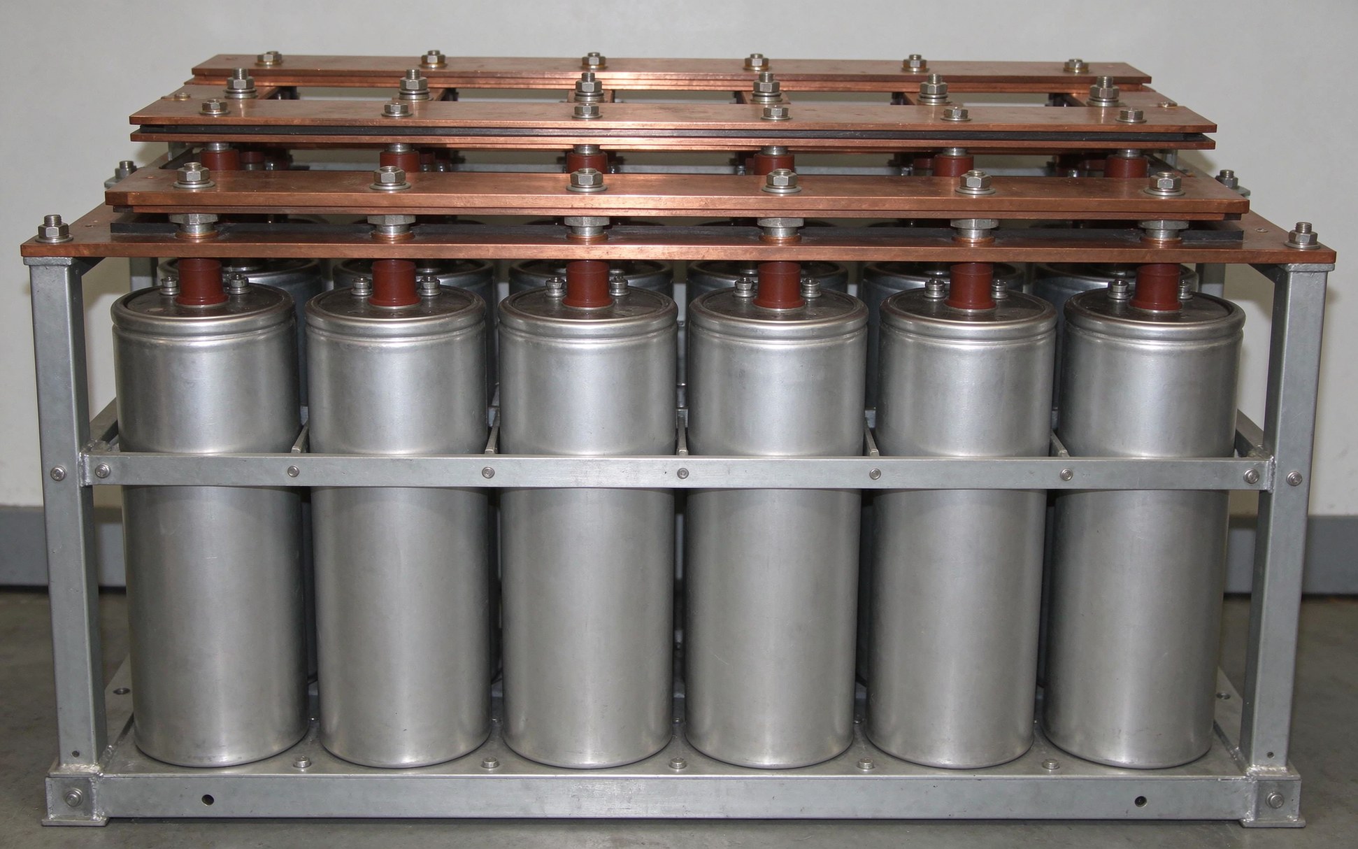
For the specific part type, the capacitor bank busbar product page covers the construction patterns — layered copper, tin-plated terminals, dielectric edge wrap — used in this exact interface.
Opposite currents in parallel conductors repel. Force per unit length is F/L = μ0 I2 / (2π d). At I = 50 kA and center-to-center spacing d = 10 mm: F/L ≈ 50 kN/m. Over a 0.5 m run, that is 25 kN — roughly 2.5 tonnes pushing the bars apart, on every shot.
Bolts, clamps and terminal studs see this cyclic load. A 105-shot year (one shot every 30 seconds over a shift) is a low-cycle fatigue problem, not a steady stress problem. M6 and M8 studs must be sized for both peak force and the fatigue cycle count; under-torqued joints relax under cyclic load and become hot spots.
Thermally, each shot raises copper a few kelvin and cooling returns it between pulses. Differential expansion between copper (~17 ppm/K), PET dielectric (~20 ppm/K) and steel fasteners (~11 ppm/K) generates interface shear at every laminate bond and every terminal washer. The thermal cycling reliability guide covers the test protocols; the vibration and bolted joint design guide covers the fastener side. Both matter in pulse duty in ways they don't in steady inverter service.
A 500 to 1,000 V spike from switch commutation rides on top of the DC bias. At 1 to 5 kV working voltage with a thin PET dielectric (0.1 to 0.2 mm), the baseline field stress is already 5 to 20 kV/mm. Fast dv/dt couples through voids in the laminate; a void of even 0.1 mm sees partial discharge at modest overvoltage.
Nomex paper and double-side fluoropolymer (DLF) constructions tolerate transient stress better than thin PET because they are thicker, more void-resistant, and small defects tend to self-heal. Edge coating — wrapping the cut laminate edge with a compatible dielectric — extends the creepage path and suppresses surface corona at the commutation spike.
Partial discharge is not a one-shot failure. It erodes the dielectric one electron avalanche at a time until a tree channel bridges the edge. Detection at qualification is non-negotiable: apply hipot plus PD measurement at the expected dv/dt, not just at DC bias. The PD-free design guide covers the construction rules, and the partial discharge resource page lists the measurement standards and acceptance bands.
A single ampacity number is meaningless for pulse duty. A usable specification has to state both the peak and the RMS envelope, plus the fault case. At minimum, ask the vendor to commit to:
Two ratings fall out of that: peak (mechanical force, terminal torque, instantaneous heating) and RMS (cooling, steady-state temperature). The harmonic current rating guide explains the RMS-side arithmetic for non-sinusoidal waveforms, and the busbar ampacity calculator is the right starting point for the RMS number once the pulse envelope is known.
Conductor choice for pulse work is not controversial: C11000 electrolytic tough-pitch copper, full anneal for bendability where needed, half-hard for straight runs. Surface finish is matt tin plating on the contact face — it stabilizes bolted-joint contact resistance over thermal cycles and resists fretting corrosion. Bright tin whiskers are a known failure mode in high-vibration environments, and tin whisker mitigation is worth a separate review for terminal faces that sit near superconducting magnet leads.
Dielectric selection follows the voltage envelope. PET is the low-cost default below roughly 1 kV working stress. Nomex paper goes where temperature and transient stress push above PET's comfort zone. DLF (double-side fluoropolymer on a copper carrier) is the premium option for the highest dv/dt edge stress. For terminal interface, M6 and M8 studs are the standard SHANYUAN offering; blade terminals and welded posts are available for kA-class pulse runs where a bolted stud would be the bottleneck.
The power electronics laminated busbar product line is the closest off-the-shelf starting point, but the pulse envelope usually forces custom geometry. Torque acceptance is documented in the terminal torque and pull acceptance guide — pull tests at qualification, torque audit at every delivery.
A busbar vendor that has only served inverter and DC-link customers will not have a pulse test protocol on file. Before you qualify them, ask for four things on paper:
If your internal engineering team is still deciding whether to run this capability in-house or outsource it, the make-vs-buy guide for laminated busbars walks through the same trade-offs for industrial converter duty. For the fusion-specific envelope, the path is almost always custom: start the conversation through custom laminated busbar engineering with your pulse envelope on the first email. The quality page lists the inspection and test records SHANYUAN provides with each batch.
Today's fusion devices fire minutes between shots. A commercial plant will pulse at grid frequency or run quasi-steady — duty cycle moves from 0.02% toward 10 to 30%. At 10% duty, RMS loss becomes roughly 30× higher, cooling becomes the dominant cost, and the busbar shifts from a pulse component to a power-distribution component.
The supply chain is already reorganizing around that shift. FIA's 2026 Supply Chain Report measured 24% spending growth in 2025 and projected another 27%; that growth shows up in every line item from copper foil to switch stack to laminated interconnect. For engineers specifying power delivery for 2026–2030 pilot plants, the window to qualify a supplier is now. The transient fault protection side — arc containment in the converter hall — is covered in the internal arc containment guide, and engineering samples for your pulse envelope can be scoped through contact SHANYUAN engineering directly.

Loop inductance decides how hard a SiC converter can switch. This guide covers the double-
Read articleAt 20 kHz the skin depth in copper is 0.47 mm - most of a thick bar carries nothing but we
Read article
Daniel Richter is the chief electrical engineer at SHANYUAN Laminated Busbars, with 15 years in laminated busbar design and current-carrying systems. He leads electrical dimensioning, DC-link layout and thermal simulation for power converters, EV platforms and HVDC stations, and holds an M.Sc. in El
Send the current profile, voltage class and terminal types — our engineers reply within one business day.
