The European Union Allowance opened 2026 above EUR 90/t, dipped below EUR 64 in March, and settled near EUR 82 by late summer (German Bundestag, 2026). Against that carbon-price backdrop, paper, food and glass line operators are no longer asking whether to electrify process heat — they are asking which feeder, which transformer and which busbar cross-section the retrofit needs. IRENA (2026) puts 2025 utility solar and onshore wind at USD 44 and USD 33 per MWh, so the electricity side of the equation has flipped too. This piece sizes the electrical side of that question, from the 10 kV feeder down to the 1000 A laminated copper bar in the boiler room.
The European Union Allowance opened 2026 above EUR 90/t, dipped below EUR 64 in March, and settled near EUR 82 by late summer (German Bundestag, 2026). Against that carbon-price backdrop, paper, food and glass line operators are no longer asking whether to electrify process heat — they are asking which feeder, which transformer and which busbar cross-section the retrofit needs. IRENA (2026) puts 2025 utility solar and onshore wind at USD 44 and USD 33 per MWh, so the electricity side of the equation has flipped too. This piece sizes the electrical side of that question, from the 10 kV feeder down to the 1000 A laminated copper bar in the boiler room.
This page is an annual rolling data page: the 2026 edition, refreshed once a year as new market data is published.
Transport and buildings have absorbed most of the electrification headlines over the last decade. Industry, by contrast, still burns gas, coal and oil on site for roughly two-thirds of its energy needs, and more than half of that is process heat — the 100–500 °C steam, hot oil and direct-fired loads that dry paper, bake food, temper glass and cook reactors. The IEA notes that over 40% of global final energy consumption is already spent on heating, and electrifying even the low-temperature slice is now the cheapest lever plants have (IEA Heat Pump Monitor, 2026).
Three numbers have moved together in 2026 and flipped the economics. First, EUA prices spent most of the year between EUR 64 and EUR 92/tCO2, with the Q3 2026 CBAM certificate reference fixed at EUR 82.32/t (European Commission, 2026). Second, new utility solar PV and onshore wind came in at USD 44 and USD 33 per MWh on a global weighted-average basis in 2025, while offshore wind fell to USD 78/MWh (IRENA, 2026). Third, electrode-boiler OEMs are quoting 10–600 MW skids with 30-minute hot-water storage that competes with gas on an annualised operating-cost basis. The grid side of these retrofit packages is where busbar engineers get pulled in.
For context on the other end of the decarbonisation stack, our colleagues covering behind-the-meter SMR power purchase agreements and fusion pilot plant pulsed-power busbars are sizing very different currents. Process-heat electrification sits in a much more mundane but much larger 1–10 MW continuous-load band.
Engineers sizing an electric heat plant in 2026 typically pick from three hardware families. Electrode and resistance boilers convert 10–100 MW of MV/LV power directly into saturated steam or pressurised hot water, usually at 10 kV or 35 kV MV feeders down to a 0.4 kV auxiliary board. The global electrode-boiler segment is estimated near USD 570 million in 2026 (Industry Research, 2026), with the high-voltage district-heating subset growing faster at roughly 11% CAGR.
MW-scale industrial heat pumps extract heat from process wastewater, cooling-tower return or ambient air and lift it to 80–160 °C. IEA (2026) puts the technical ceiling for today's large pumps at 140–160 °C, with paper, food and chemicals able to cover nearly 30% of their combined low-temperature heat demand this way. Each 5–10 MW pump train is driven by a 6–10 kV variable-frequency drive on a 4-pole induction or synchronous-reluctance motor.
Direct electric heating on continuous lines — radiant panels in glass lehrs, infrared ovens in food baking, immersion electrodes in paper pulp — runs as resistive or inductive loads fed from 400 V/690 V LV switchboards. They are smaller per point (100–800 kW) but numerous, and they share the same LV busbar as the e-boiler auxiliaries. You can see how the inverter-driven side of the pump train is treated in our piece on heat-pump inverter busbar design; this article focuses on the main and feeder boards inside the boiler house itself.
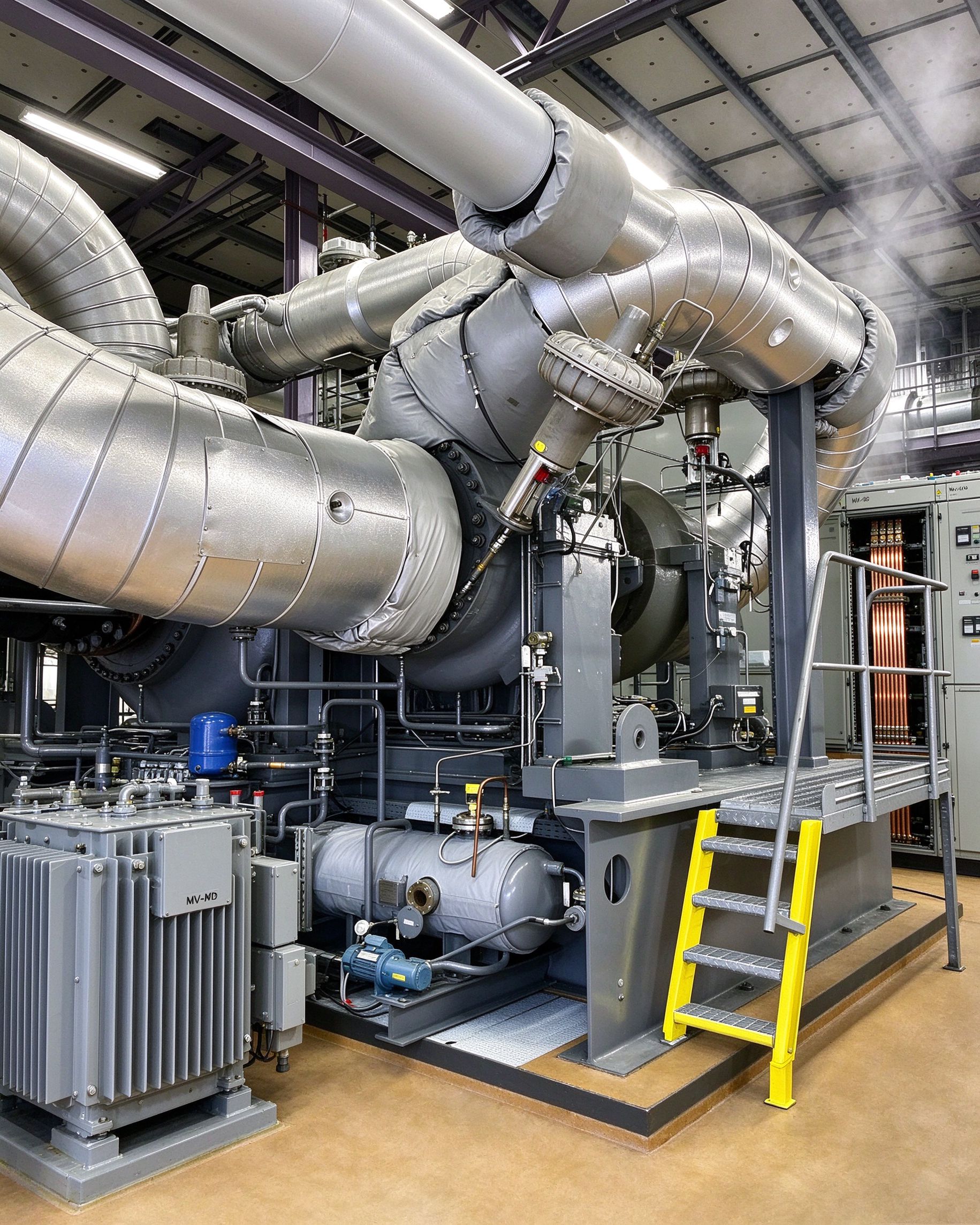
Three sectors dominate the early retrofit wave, and each loads the busbar differently.
What ties them together is the electrical room layout: a single 10–20 kV utility feeder, one or two oil or dry-type transformers, a 0.4 kV main switchboard with a 1600–3200 A main bus, and 6–14 outgoing feeders to the e-boiler SCR cubicles, the heat-pump VFDs and the line distribution panels. That is the board whose copper we are sizing in the rest of this article. The same busbar architecture is described from a standards angle in our IEC 61439 busbar requirements guide.
Replacing a 10 t/h gas boiler (about 7 MW thermal) with an electrode boiler at a coefficient of performance near 1.0 needs roughly 7 MW of electric input, plus 15% auxiliaries. At 10 kV three-phase, that is around 450 A on the MV feeder. At 0.4 kV LV, the equivalent is close to 11,000 A — which is why almost all boilers above ~5 MW connect on MV and only step down locally.
Plant engineers often underestimate two grid-side numbers. The first is maximum demand: e-boilers used for demand-side response ramp from 0 to 100% in under 5 minutes, so the utility meter and the incoming breaker must be sized for full MW, not average. The second is short-circuit level: a 10 MVA service transformer with 6% impedance delivers around 140 kA prospective at the LV side, which forces the busbar bracing and the assembly rating toward IEC 61439-1 short-time withstand levels. More on that grid-side demand side is in our piece on grid transformer and busbar demand.
| Thermal load | Electric input (≈) | MV feeder at 10 kV | LV main at 0.4 kV | Typical busbar |
|---|---|---|---|---|
| 2 MW steam | 2.3 MW | ~135 A | ~3,300 A | 2 × 100 × 10 mm Cu per phase |
| 5 MW hot water | 5.5 MW | ~320 A | ~7,900 A | 3 × 100 × 10 mm Cu per phase |
| 10 MW heat-pump heat | 3.3 MW elec. (COP 3) | ~190 A | ~4,700 A | 2 × 80 × 10 mm Cu per phase |
Those LV numbers assume transformer secondary voltage and a 0.95 power factor; your project numbers will move ±10% with site voltage and cable routing.
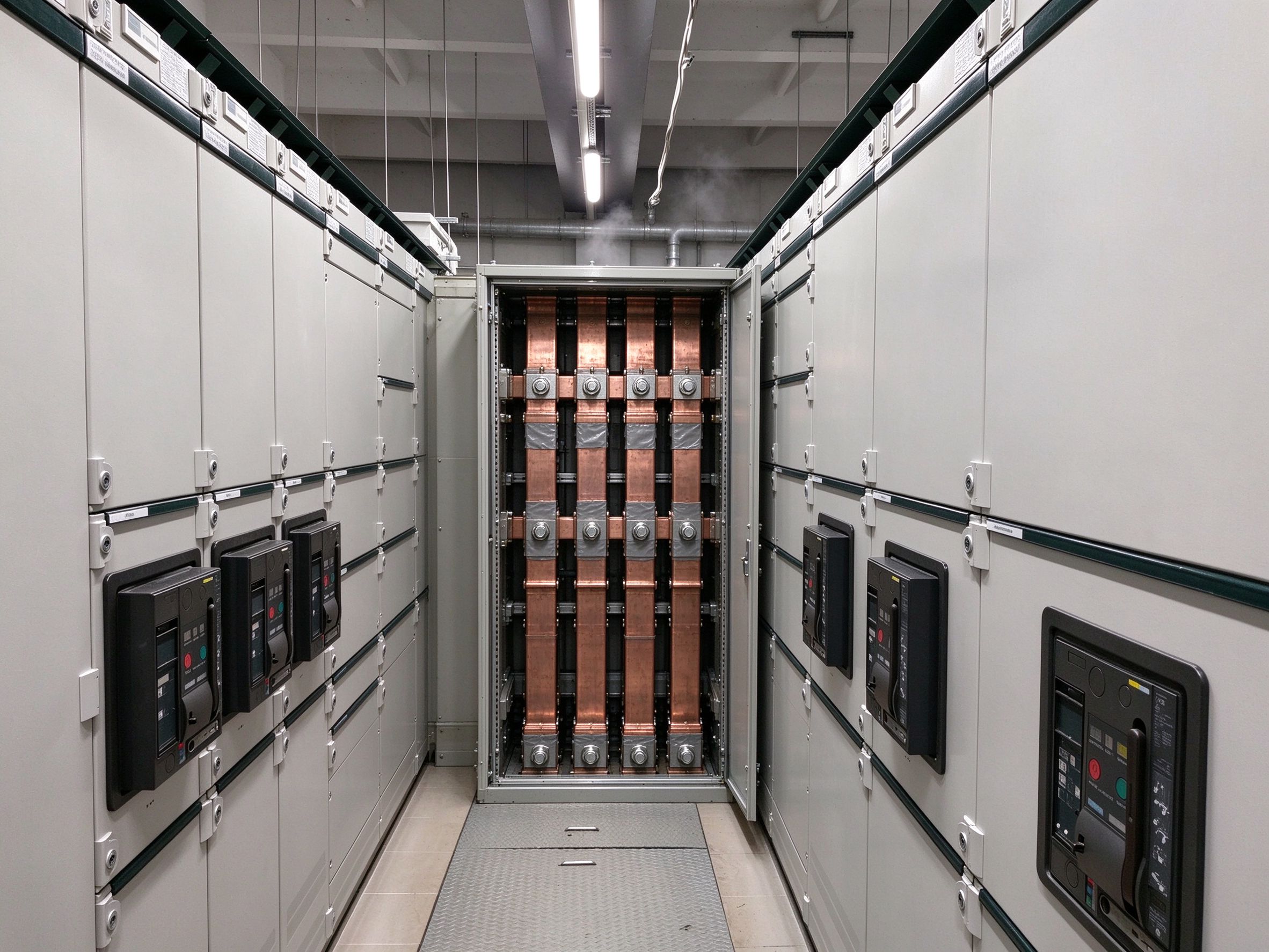
Inside the 0.4 kV boiler-room board, the incoming main bus usually lands at 1600–3200 A, but the feeders to each e-boiler electrode chamber, each VFD and each distribution panel sit in the 400–1250 A range. That is the sweet spot for single or double-layer laminated copper busbar on C11000 stock, tin-plated, with PET or Nomex dielectric edges and M6/M8 stud terminals — exactly the geometry SHANYUAN ships for LV switchgear.
Above about 800 A per phase, designers stop using a single thick bar and switch to parallel shunt bars: two or three thinner plates in parallel, separated by a dielectric film and bolted together at the ends. Parallel plates buy three things at once. They increase the coolable surface area per amp, they raise the panel's short-circuit dynamic bracing (the bars couple to each other and to the support insulators), and they let the same plate stock cover 800, 1000 and 1250 A feeder ratings without a new tool. The trade-off is current sharing: skin and proximity effects make the outer plates carry more than the inner ones, and unequal contact resistance at the bolts worsens it. We cover the physics in parallel busbar current sharing design.
A practical 1000 A feeder bar for a boiler-room VFD cubicle is two 60 × 6 mm tin-plated C11000 copper plates, laminated with a 0.25 mm PET film between layers, M8 studs at 100 mm pitch, rated at 30 K rise over 35 °C ambient. That geometry fits a standard 800 mm-wide MCC compartment and clears the IEC 61439-1 clearance and creepage numbers for 690 V class. If you want to push numbers before releasing drawings, our busbar ampacity calculator walks the same arithmetic.
This is the calculation that trips up retrofit teams. IEC 61439-1 declares the assembly at a reference ambient of 35 °C 24-hour average, with a 40 °C absolute maximum (ABB technical application paper, 2024). A busbar tested to 30 K rise under those conditions hits a bar temperature of about 65 °C — well below the 105–125 °C limit for tin-plated copper with PET or Nomex film.
Now put that same bar inside an electric boiler room. The e-boiler itself rejects 2–3% of input as waste heat through its transformer and SCR cubicles, the room is rarely air-conditioned, and in summer the measured ambient at the board top box hits 40 °C. To keep the bar at the same 65 °C absolute temperature, allowable temperature rise drops from 30 K to 25 K. Because Joule heating P = I²R scales with the square of current and ΔT is roughly proportional to P at steady state, the derated current is:
I_derated = I_rated × sqrt(ΔT_allowable / ΔT_rated) = 1000 × sqrt(25 / 30) ≈ 913 A
Real-world switchgear manufacturer tables (for example the Zucchini-style K1 ambient multiplier series) give a factor of about 0.95 when moving from a 35 °C rated board to a 40 °C installation, i.e. roughly 950 A. The engineering takeaway is the same: a 1000 A busbar in a 40 °C boiler room delivers about 920–950 A, not 1000 A. If the room also sees summer peaks of 45 °C, the factor drops toward 0.88, and a 1000 A bar is really an 880 A bar. Add harmonic derating from VFDs (see next section) and you are typically at 800–850 A usable.
The corollary: up-size by one rating class. A feeder engineered for 800 A continuous should be built with a 1000 A class bar, not a 800 A bar, because the ambient and harmonic penalties eat exactly that margin. This temperature-rise arithmetic is also why we push customers to read busbar temperature-rise test methods before signing the type-test report acceptance.
MW heat pumps, boiler feed pumps and combustion-fan replacement motors are almost universally driven by variable-frequency drives in 2026. A 6-pulse diode-front-end VFD draws a non-sinusoidal line current rich in 5th, 7th, 11th and 13th harmonics. Those harmonics do two things to a DC busbar that the RMS meter does not see.
First, they add skin-effect and proximity-effect losses at higher frequencies. A 5th harmonic at 300 Hz penetrates copper to about 42% of the depth it has at 50 Hz, and the 11th harmonic at 550 Hz to about 28%. The effective AC resistance of a 60 × 6 mm plate rises 10–20% at a typical VFD-rich loading mix, and the extra watts show up as bar temperature rather than as current on the ammeter. Second, harmonic currents add to the fundamental in RMS terms: a 10% THD current raises I²R heating by 1% on its own, but combined with the skin-effect resistance rise, the bar runs 5–8 K hotter than the fundamental-only calculation predicts.
The fix is not to over-build the bar blindly. It is to ask the VFD supplier for the line-current spectrum and then apply a derating factor between 0.92 and 0.98, depending on the K-factor. We walk through the arithmetic in harmonic-current busbar rating for VFDs. For a boiler room with two 2 MW VFD-driven heat pumps, we typically spec the LV main bus one size up from the fundamental RMS number and ask the bar manufacturer to confirm the rise test at the harmonic spectrum actually measured on site.
It is worth being explicit about the electrical chain inside a heat-pump drive, because customers often confuse the LV AC busbar in the switchroom with the DC-link busbar inside the VFD cabinet. From the transformer secondary, power arrives as 400 V or 690 V AC onto the LV switchboard busbar — the copper stack we have been sizing in sections 5–7. It then travels by cable or busway to the VFD input terminals, where a 6- or 12-pulse rectifier converts it to a 900–1200 V DC link. The DC link itself uses a laminated copper busbar between the DC capacitors and the IGBT modules, and that bar has to be a low-inductance, tightly-coupled sandwich to suppress switching overvoltage.
So a 10 MW heat-pump installation actually contains two busbar problems: the room-side AC bar (~1000 A, 50/60 Hz, derated for ambient and harmonics) and the drive-side DC-link bar (same kVA, but with kHz switching edges and a strict loop-inductance budget). SHANYUAN makes both families: the LV switchgear bar as a rigid tin-plated C11000 assembly, and the power-electronics DC-link bar as a multi-layer laminated stack with C11000 plates and PET/Nomex/DLF dielectric. If you are comparing build options, our laminated busbar make-vs-buy guide lays out when to buy off the shelf and when to custom-spec.
For the main LV board itself, the relevant product family on our side is the LV switchgear busbar line — 1 to 6+ layers, ~1000 A class, tin-plated, M6/M8 stud, blade or welded terminals.
Electric boiler rooms are wet rooms. Steam leaks, condensate drips from insulated pipe flanges, wash-down hoses get used on the floor, and the relative humidity swings from 40% in winter to 90%+ in summer when a 5 MW electrode boiler cycles. A board rated IP30 for a clean electrical room will track, surface-leak and eventually flash over at the busbar insulation edges.
Three practical rules come out of this. First, the assembly should be at least IP42 for indoor boiler rooms, IP54 for positions within 3 m of a boiler water-wall, and IP55 if wash-down is routine. Second, the busbar insulation system — the PET/Nomex wrap and the end-coating — needs to survive 95% RH at 40 °C without surface tracking, and the creepage distances on the terminal studs need the pollution-degree-3 clearance values from IEC 61439-1, not the cleaner pollution-degree-2 numbers used in datacenters. Third, the room needs positive ventilation and a low-space heater in each cubicle during shutdown weeks, because condensation on a cold energised bar is the fastest way to get a surface-tracking fault. We go deeper on this in humidity and coastal busbar insulation selection.
On the SHANYUAN side, the standard dielectric stack for wet-room bars is PET face layers with a DLF edge seal, tin plating on all exposed copper (which resists the oxide film that bare copper grows in humid air) and epoxy end-coating. We do not recommend bare-tin or bare-tin-over-nickel for rooms that see weekly wash-down.
When a 7 MW electrode boiler replaces a 10 t/h gas boiler, the utility feeder and the local transformer are rarely oversized for it. A factory built around gas has spare LV board space but almost never spare transformer capacity — the existing 2 MVA service transformer was sized for the machine drives and lighting. Adding 7 MW of electric heat means a new 10–12.5 MVA transformer and a new MV ring main unit.
Three sizing choices matter. Pick the transformer at 1.1–1.2× the steady electric heat load, because e-boilers run at 100% for 6,000+ hours a year and you want cooling margin. Choose a dry-type or cast-coil unit if the boiler room is damp (oil-filled tanks weep in humid air and the bund becomes a slip hazard). Specify a 6% impedance, not a 4% unit, to hold the LV short-circuit level inside the 50 kA/1 s rating of a standard 1600 A MCC — going to 8% impedance pushes fault level down but worsens voltage dip on VFD inrush. And remember that the heat-pump train, at COP 3, draws only ~3.3 MW electric for 10 MW thermal, so its transformer can be smaller than the e-boiler's even though the thermal duty looks comparable.
On protection, the main LV breaker should be a 3200 A four-pole with electronic trip set L-I-G, and the outgoing feeders to e-boiler SCR cubicles need earth-fault protection with a 300 mA sensitive setting — electrode boilers operate on demineralised water and can develop leakage paths that do not trip a standard 30 A ground fault. If your project involves arc-flash analysis on the new board, our colleagues wrote busbar internal arc containment guidance, and void inspection on laminated stacks is covered in busbar void and CT inspection practice.
We are Rizhao Shanyuan Electronic Components Co., Ltd., based in Wulian, Rizhao, Shandong, manufacturing laminated copper busbars since March 2012 across a 17,200 m² plant, exporting to more than 20 countries. For industrial-heat retrofit boards, the parts that leave our line usually look like this.
We do not ship certified switchgear assemblies; we supply the copper conductor sub-assemblies that assembly builders install into IEC 61439-1 and UL 898-type boards. Every project goes through our standard drawing-review, sample and series-production workflow, which you can read about on the sample-to-series procurement page. If you have a 1–10 MW e-boiler or heat-pump retrofit in design, send us the one-line diagram and the ambient/harmonic assumptions through the contact page and we will come back with a bar cross-section and a rise estimate within two working days.
Before the 0.4 kV board goes out for tender, we would want the following numbers on the drawing set. Tick them off in order — each one changes the busbar cross-section.
Run the derating arithmetic from section 6 first — a 1000 A bar in a 40 °C room is really a 930–950 A bar, and harmonic loading trims another 5–8%. Size the copper one rating class above the calculated RMS, and you will not be back in 18 months opening the board up at 45 °C summer peaks. For background on the broader industrial electrification context, the industrial applications page collects the related reference designs we have published over the last two years.
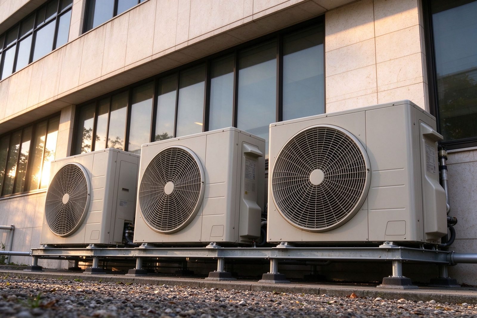
Heat pump demand recovered in 2026, and the units are getting larger, quieter and more inv
Read article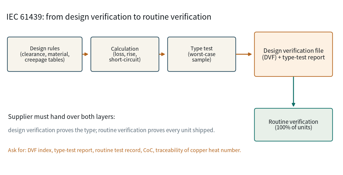
IEC 61439 governs the assembly, not the copper bar. That is exactly why busbar suppliers a
Read article
Emily Novak analyses energy-storage, grid and new-energy markets and turns them into procurement-ready technical content. With 7 years in energy market research and technical writing, she covers BESS growth, HVDC projects and regulatory shifts that change busbar demand. She holds an M.A. in Energy E
Send the current profile, voltage class and terminal types — our engineers reply within one business day.
