Terminal quality is usually judged by feel: the fitter tightens until it seems right, and the joint either survives or comes back. That works until a program reaches volume, or until a customer asks for evidence. Torque windows and pull limits convert the feel into a specification a line can hold.
Terminal quality is usually judged by feel: the fitter tightens until it seems right, and the joint either survives or comes back. That works until a program reaches volume, or until a customer asks for evidence. Torque windows and pull limits convert the feel into a specification a line can hold.
A torque check asks whether the fastener carries the clamp load the design assumed. A pull test asks whether the joint — fastener plus terminal plus busbar — resists the mechanical load the installation will apply. They are related but not interchangeable, and a program that only does one of them has a blind spot.
Torque alone can be satisfied by a joint that is tight but has poor contact area: a burr under the washer, a terminal face that is not flat, or a stud that bottoms in a blind hole. Pull alone can be satisfied by a joint that holds mechanically but has high resistance, because the pull test measures force, not micro-ohms.
The acceptance standard therefore has three measurements, not two: applied torque, resulting contact resistance, and mechanical pull or push-out limit. Each has its own sample plan and its own record, and together they describe a joint rather than an operation.
The measurement context for insulation is separate; see hipot acceptance and partial discharge.
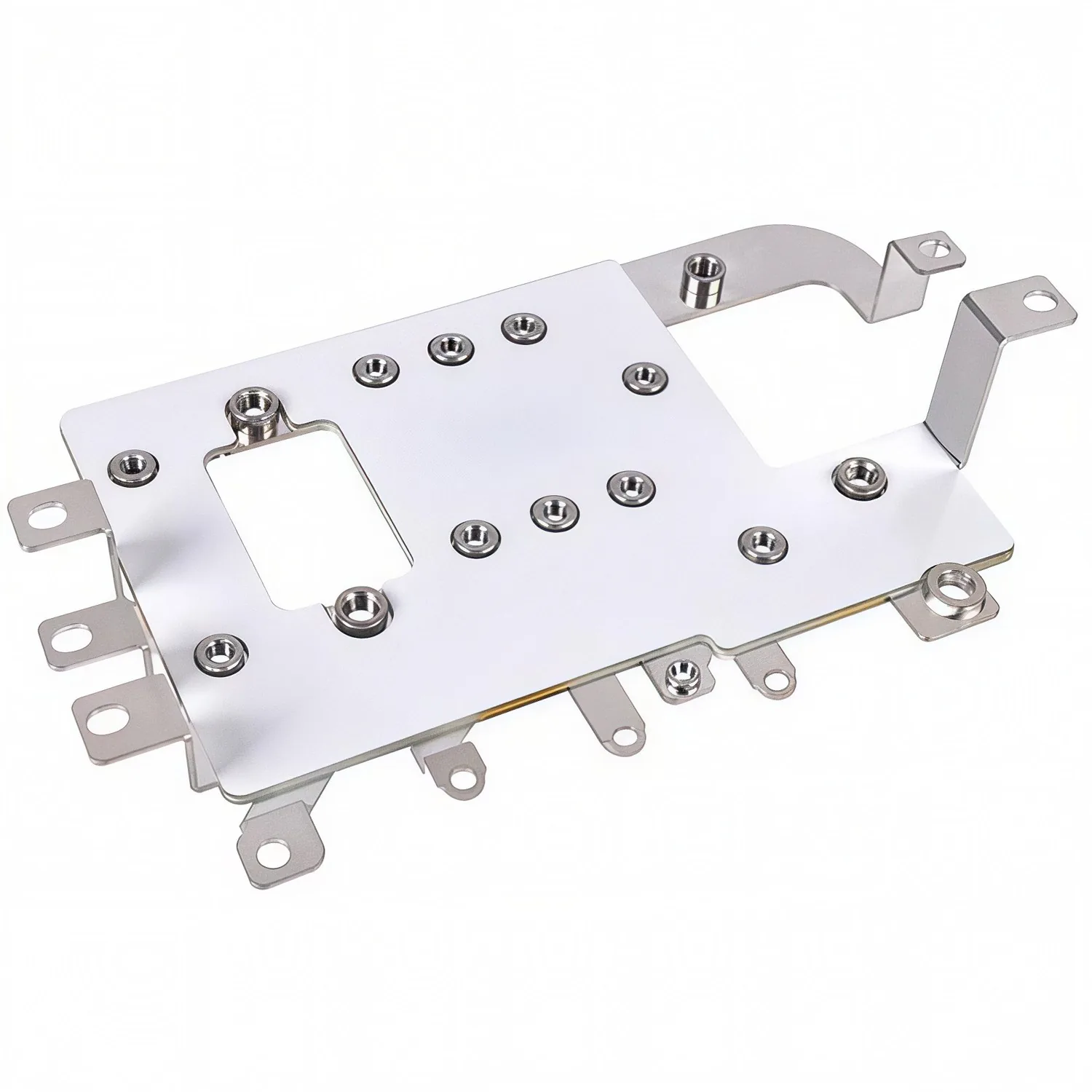
The torque window should come from the fastener supplier's data for the specific combination of stud, washer, nut and mating material, adjusted for the fact that a busbar joint is usually a soft-material joint. Copper and aluminium deform under the washer, so the clamp load decays after tightening; the initial torque has to account for that relaxation rather than being set at the fastener's maximum.
For the M6 and M8 studs used on most laminated busbars, published windows commonly sit in the 8–12 N·m range for M6 and 18–25 N·m for M8, with M10 and M12 higher. Those are starting points, not universal values: the correct window depends on stud grade, thread lubrication, washer type and the terminal material. A dry steel nut on a stainless stud and a lubricated nut on the same stud do not produce the same clamp load at the same torque.
The window should be stated as a nominal with a tolerance, verified on the actual hardware, and recorded on the drawing. "Tighten securely" is not a specification, and it is the phrase that produces the largest variation between shifts.
The terminal options these windows apply to are listed in busbar connections.
There are two ways to verify torque, and they answer different questions. The first is to control the installation with a calibrated torque wrench or a preset driver, and to record the setting rather than the result. This is production control: it prevents over- and under-tightening but does not prove that each joint received the intended torque.
The second is to measure the breakaway torque on a sample: tighten to nominal, mark the nut and washer, then a defined interval later apply torque in the tightening direction and record the value at which movement begins. A breakaway value below the window indicates relaxation or a thread problem; a value far above it indicates galling or a bottomed fastener.
Breakaway testing destroys the joint's traceability in the sense that the joint has now been re-tightened, so it belongs on a sample that is scrapped or reworked, never on delivered hardware. That distinction has to be explicit in the inspection instruction, or a well-meaning inspector will test every joint and ship none of them correctly.
A pull test applies an axial load to the terminal and records the load at which the joint yields, slips or fails. For a stud terminal, the load path is through the stud into the busbar; for a welded tab, through the weld; for a blade terminal, through the crimp or the solder joint. Each has a different expected failure mode, and the acceptance limit should name the mode that is acceptable.
A typical specification states a proof load rather than a breaking load: the joint must withstand a defined force for a defined time without movement, deformation or a resistance change beyond a limit. That is a more useful production test than a destructive pull to failure, because it can be applied to a sample and the result is a pass or fail rather than a number that requires interpretation.
The proof load should be derived from the installation, not chosen arbitrarily. A busbar in a stationary rack sees handling loads and vibration; a busbar in a traction pack sees acceleration and shock. The applicable standard for the application sets the acceleration factor, and the proof load follows from the mass of the terminal and the attached hardware.
Installation loads by application are described under rail and EV applications.
Two joints can pass torque and pull and still differ by a factor of three in contact resistance. Measuring it requires a four-wire method: a current source across the joint and a separate voltage sense at defined points, so that the probe and lead resistance do not enter the result. The measurement is usually reported in micro-ohms at a defined current, and the limit is set by the temperature rise the joint may produce at rated current.
The practical limit for a bolted copper joint in good condition is in the low micro-ohm range, and the acceptance criterion should be a maximum, not a typical. A joint that measures 20 µΩ where the design assumed 10 µΩ will run noticeably hotter at 1,000 A, and the heat sits exactly where the insulation is thinnest.
Contact resistance also gives the line a way to detect problems that torque control cannot: a burr, a contaminated face, a washer installed upside down or a plating defect. Those are the failures that pass a wrench and fail in the field.
The thermal consequence of a high-resistance joint is covered in thermal management.
The sampling plan should follow the process risk, not the part count. A joint produced by a calibrated preset driver on a stable process is a different risk from a joint assembled by hand with a torque wrench and a moving operator. The first can be verified by audit; the second needs a sample per shift.
A workable production plan uses three tiers. Every joint: controlled torque with a calibrated tool and a recorded setting. Every lot: contact resistance on a sample sized to the lot, with a zero-failure acceptance for safety-critical joints and a defined AQL for others. Every change: a destructive pull and a breakaway torque check when a fastener, washer, plating or terminal supplier changes.
The sample size itself can be modest if the process is controlled. What matters is that the sample is random within the lot and that the record identifies the lot. A test that cannot be tied to a shipment is a test that proves nothing about the shipment.
The hardware around the joint is part of the joint. A flat washer spreads the clamp load; a split washer adds a spring that may or may not survive the thermal cycle; a serrated flange washer bites the plating and can improve electrical contact while damaging the corrosion barrier. Each choice changes the torque window and the pull result.
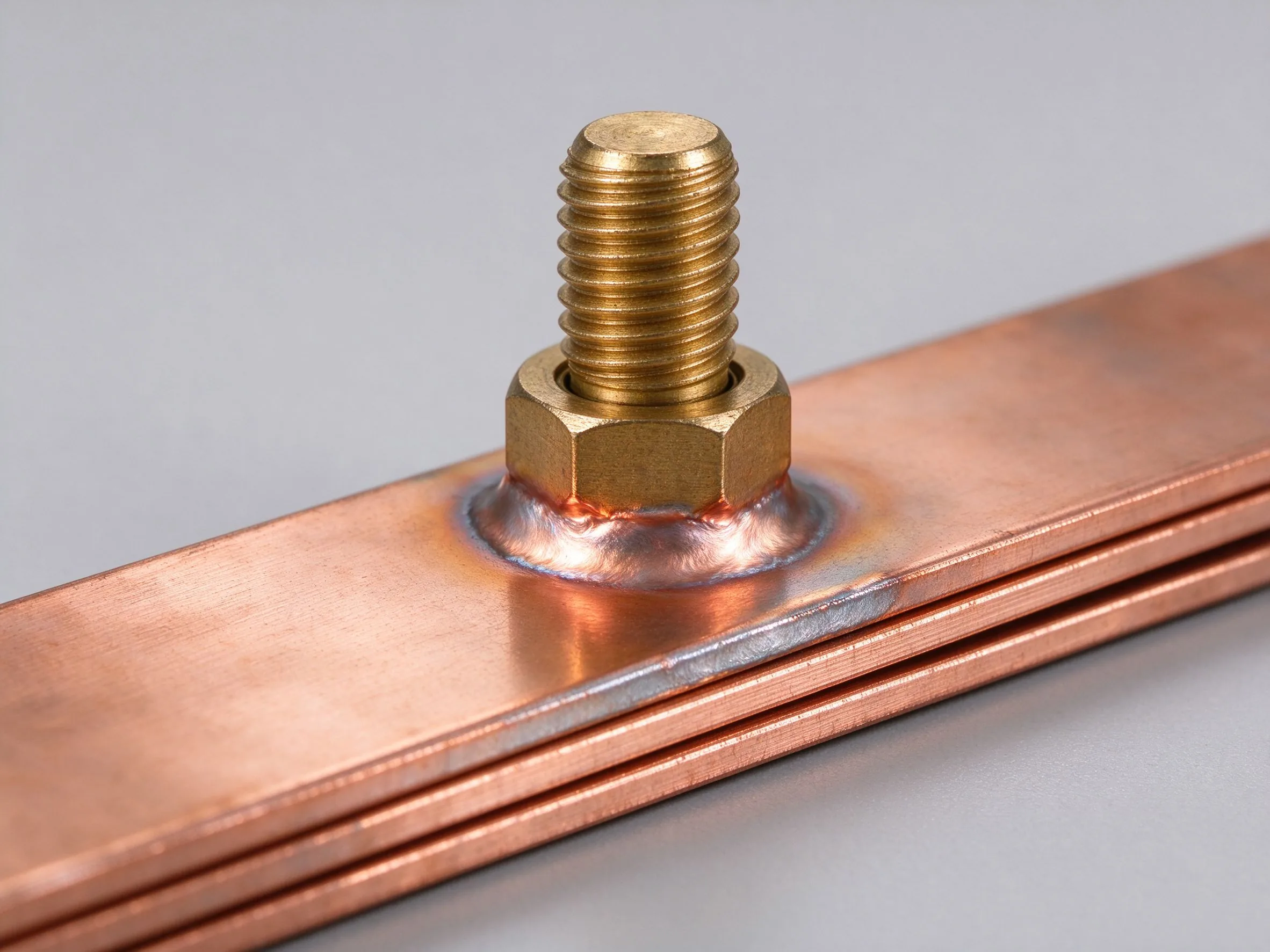
For busbar terminals the common specification is a hardened flat washer plus a spring or Belleville washer, with the stud grade matched to the nut to avoid galling. Stainless studs are common for corrosion resistance but have lower conductivity than brass or copper alloy, which is why the stud is not the preferred current path and the joint relies on face-to-face contact.
The plating on the terminal matters here too. Tin on copper is the default and behaves predictably under clamp load; silver has lower resistance but tarnishes and is usually reserved for specific contact systems. Mixing plated and bare surfaces in one joint is a corrosion cell, and it is the kind of detail that survives a factory test and fails in a humid installation.
Stud, blade and welded terminal designs are compared in terminal machining.
A joint that measures correctly at room temperature can lose clamp load after a few hundred thermal cycles, because the copper and the fastener expand at different rates and the soft material under the washer creeps. The result is a joint that passed acceptance and later runs hot.
The test that catches this is a retained-torque check after a defined cycle profile: heat the assembly to its rated temperature rise, hold, cool, repeat, then measure breakaway torque on a sample. A loss of more than a defined percentage of the initial value indicates that the washer stack or the initial torque is inadequate for the application.
Belleville or wave washers are the usual mitigation because they maintain clamp load across the expansion range. Their specification belongs on the drawing, with the stack order and the installed height, because a washer installed in the wrong sequence is worse than no washer at all.
Cycle testing practice is set out in thermal cycling reliability.
The acceptance document should be short enough to be used on the line and specific enough to be audited. It needs five elements: the joint configuration with a drawing reference, the torque window with the tool and calibration requirement, the contact resistance limit with the measurement method, the pull or proof load with the sample plan, and the record that ties the result to a lot.
Two more elements make it usable across shifts: a visual acceptance criterion — washer present, correct orientation, no burrs, no cracked insulation at the terminal — and a non-conformance path that says what happens to a joint that fails. Rework of a failed joint usually means replacing the hardware, not re-tightening, because the plating and the copper have already been deformed.
The standard should also state what is not allowed: impact drivers on terminals, lubrication not specified on the drawing, re-use of deformed washers, and tightening a joint that has already been at temperature without inspection. Those prohibitions prevent more failures than any test.
The system-level requirements sit in the standards hub, and process control on the quality page.
The record for each lot should carry the part number, the lot or batch, the torque tool identification and calibration date, the sample results for contact resistance and pull, the operator or cell, and the date. If the joint is safety-critical, the record should also carry the fastener lot.
The purpose is not paperwork. It is containment: when a customer reports a hot joint, the first question is which lots are affected, and a record that ties torque and resistance data to a shipment answers it in minutes. A record that only says "inspected" answers nothing.
Retention periods vary by customer and by regulation, but the practical rule is to keep the records for the life of the program plus the warranty period. Electronic records that can be exported are worth more than paper that has to be searched, particularly when the customer's audit arrives with a sample request.
The wider audit file is described in the factory audit checklist.
Five failures are common enough to name. A burr or chip under the washer reduces contact area while the torque reads correctly. A terminal face that is not flat rocks under load and produces a high-resistance line contact. A stud that bottoms in a blind hole gives a false torque reading because the fastener is loading the hole bottom, not the joint.
Plating damage from a serrated washer or an impact driver exposes copper, which oxidises and raises resistance over time. And a joint assembled with the wrong washer stack loses clamp load after cycling even though the initial torque was correct.
Each of these has a specific detection method. Burrs are found by visual inspection at the terminal face before assembly. Flatness is found by a straightness check or a witness mark. Bottoming is found by checking stud engagement against the hole depth. Plating damage is found by visual inspection after tightening. Washer stack errors are found by a first-article check and a line-side visual standard.
Joint-related field failures are also discussed in connection failure analysis.
For a new program, the sequence is: define the joint from the application loads, select the hardware, run a first-article torque-to-breakaway and pull test to establish the window, run a thermal cycle and re-measure retention, then freeze the drawing with the window, the hardware stack and the inspection method. Only then write the production instruction.
That sequence takes two to three weeks and prevents the most expensive outcome: a drawing released with a torque value that nobody verified, and a production line that discovers the problem at the customer's incoming inspection.
For programs already in production, the same work can be done as a validation study on current hardware. If the study shows the window is wrong, the change is a drawing revision plus a line instruction, which is cheaper than a field campaign and much cheaper than a recall.
Qualification sequence from sample to series is in sample-to-series procurement.
The inspection method follows the terminal type, and treating all terminals the same is how a line ends up testing the wrong thing. Four types dominate laminated busbar work, and each has a different critical point.
A stud terminal is a fastener joint. The critical points are the stud's engagement into the bar, the flatness of the contact face, the washer stack and the torque applied. A stud that is welded or friction-locked into the bar should be checked for push-out before it is ever torqued, because a loose stud will read correctly on a torque wrench and move under load.
A blade terminal is a clamped or inserted joint. The critical points are blade thickness and width against the mating connector's specification, the contact area, and the retention force. The pull test here is a push-out test in the insertion direction, and the acceptance limit comes from the connector standard rather than from the busbar drawing.
A welded tab is a metallurgical joint. The critical points are weld penetration, porosity and the heat-affected zone, and the inspection is visual plus a destructive peel or cross-section on a sample. Torque is irrelevant because there is no fastener, and a pull test to a proof load is the production check.
A crimped or compression terminal is a deformation joint. The critical points are crimp height, pull-out force and the tool calibration, and the standard is usually the terminal supplier's rather than the busbar fabricator's. Mixing this up is common: a fabricator applies a busbar torque window to a crimped connection and concludes the joint is fine because the fastener is tight.
The route card is where the acceptance standard meets the shift. A good card for a busbar with bolted terminals carries the part number, the operation sequence, the torque tool setting and its calibration date, the hardware stack with the washer order, the contact resistance sample requirement, the visual criteria, and a signature field per operation.
The failure mode of a bad route card is always the same: it records that an operation happened without recording what the operation was. A card that says "tighten terminals" and a signature tells an auditor nothing about the torque, the hardware or the sample. It also tells the next shift nothing, which is how a process drifts between shifts without anyone noticing.
Two design choices make a card usable. Place the specification next to the operation rather than on a separate drawing that the operator has to fetch, and make the non-conformance path visible on the card so a failed joint is recorded rather than quietly reworked. Both are cheap, and both reduce the gap between the written standard and the shipped part.
Digital cards are worth the investment at volume because they can enforce the torque setting, capture the tool identification automatically and export the lot record that the customer will ask for. At low volume a paper card with a pre-printed specification and a sample tally works, provided the specification is actually printed rather than referenced.
The terminal is where a laminated busbar meets the outside world. This guide covers M6/M8
Read article
A hipot test proves the insulation did not break down in the second it was stressed. It do
Read article
Nadia Rahman is a quality and compliance engineer with 9 years in electrical-component quality systems. She manages SHANYUAN's ISO 9001 and IATF 16949 programmes, incoming and outgoing inspection, and UL/IEC compliance documentation. She holds a B.Sc. in Industrial Engineering from the Universi
Send the current profile, voltage class and terminal types — our engineers reply within one business day.
