A 30 kA internal arc in a 400 V busbar compartment releases roughly 10–30 MJ of energy in one second, heating the air inside the cubicle to thousands of degrees and driving a pressure wave that can lift doors, eject cover plates, and project ionized gas horizontally past the cabinet front. IEC 61439-1:2020 treats internal arc withstand (IAC) as an optional designation, not a default: if the manufacturer has not tested and declared it, the assembly has no IAC rating at all. This guide explains what the designation means, how the busbar and compartment geometry change the outcome, and how to write the requirement onto your drawing without confusing equipment withstand with personnel arc-flash protection.
A 30 kA internal arc in a 400 V busbar compartment releases roughly 10–30 MJ of energy in one second, heating the air inside the cubicle to thousands of degrees and driving a pressure wave that can lift doors, eject cover plates, and project ionized gas horizontally past the cabinet front. IEC 61439-1:2020 treats internal arc withstand (IAC) as an optional designation, not a default: if the manufacturer has not tested and declared it, the assembly has no IAC rating at all. This guide explains what the designation means, how the busbar and compartment geometry change the outcome, and how to write the requirement onto your drawing without confusing equipment withstand with personnel arc-flash protection.
An internal arc forms when a phase-to-phase or phase-to-earth fault occurs inside the metal-enclosed assembly, usually at a busbar joint, a cable termination, or a damaged insulating support. The fault current is limited by the upstream transformer and breakers; until the protection device trips, the arc itself is a plasma channel several thousand degrees hot that heats, ionizes, and pressurizes the air inside the cubicle.
Internal arc containment is the ability of the assembled switchgear to withstand that arc for its declared test duration without, on accessible sides, igniting indicator gauze, ejecting parts that could harm standing personnel, or compromising the integrity of the enclosure. It is an equipment survival and boundary-containment rating, not a rating that says a person can stand in front of the door during the fault. That distinction matters because buyers often write \"I-rated\" on a one-line drawing and assume it covers arc-flash PPE, which it does not. We cover the split in our standards reference library and revisit it in section 11 of this guide.
IEC 61439-1:2020 clause 7.7.3 sets out the optional IAC designation. If a manufacturer chooses to declare it, the assembly must be type-tested in accordance with IEC 61641, the dedicated test guide for low-voltage assemblies under internal arc conditions. If no declaration is made, the phrase \"internal arc\" simply does not apply to that enclosure.
An IAC designation on a nameplate is a compact code built from four pieces of information: the accessible side(s) tested, the test current, the duration, and the method of arc initiation. A typical full designation reads IAC-A, AFLR, 30 kA, 1 s, IAC. Each token has a specific meaning, and leaving one out leaves a gap the customer has to fill by phone.
The accessible-side letter tells the witness cotton gauze where it is placed around the cubicle during the test. Letter A means gauze is placed on all four sides, the top, and the bottom; B restricts the test to front, sides, and top; C restricts it to the front only. A rear-rated \"R\" side is added when the cubicle is intended to be backed up against a wall or behind a chain-link barrier that personnel do not normally cross.
The letters after the dash — often written FL for front-left, FR for front-right, FLR, AFLR, and so on — list exactly which faces are covered by indicator gauze. If the cubicle will be installed against a wall on the rear, requesting an R rating can be dropped from the spec, but you must then verify in writing that the installation boundary matches the tested boundary. Mixing a front-only test with a floor-standing installation where the sides are walkable is a common non-conformance found during factory acceptance.
The table below summarizes the four fields a buyer should read off the nameplate or type-test certificate. Treat each row as a separate, independently verified claim — a cabinet that passes 30 kA/1 s on the front is not automatically a 50 kA/1 s cabinet on the sides.
| Field | Typical values | What it proves |
|---|---|---|
| Accessible side class | A / B / C | Which faces of the cubicle are surrounded by indicator gauze during the test |
| Side letters | F, L, R, FL, FR, FLR, AFLR | Physical faces (front, left, rear) on which indicator gauze is actually placed |
| Test current Iarc | 16 kA, 30 kA, 50 kA, 65 kA (rms) | Prospective symmetrical fault current the source supplies to the arc |
| Duration tarc | 0.1 s, 0.5 s, 1 s | Time the arc is permitted to burn before the test circuit opens |
| Arc initiation point | Busbar zone, cable zone, both | Where the test lab fixes the ignition point; one point does not cover the other |
Two engineering notes follow from this table. First, duration matters more than peak current in practice: a 30 kA/1 s test exposes the enclosure to roughly nine times the I²t of a 30 kA/0.3 s test, because thermal energy scales with I²t. Second, the busbar-zone and cable-zone tests are separate events. A cubicle that has only been tested with the arc initiated on the busbar side cannot be assumed safe in the cable-wiring zone, where loose conductor strands and terminated lugs are equally likely sources.
When the arc strikes, three things happen in rapid succession. The arc column superheats the air in its immediate path; that air expands and is compressed by the surrounding cooler air, producing a pressure front that propagates outward at close to the speed of sound. At the same time, the copper and steel near the arc melt and vaporize, adding metal vapor that raises the arc voltage and sustains the plasma. Finally, the heat radiated to the enclosure walls burns paint, deforms thin sheet, and can ignite any insulating material that is not itself arc-resistant.
Typical measured pressure rises inside a sealed 400 A cubicle during a 30 kA arc run reach several kPa in the first 50 ms, peaking near 10–20 kPa before the pressure relief opens. A 2 kPa uniform load on a 2 m × 0.6 m door is already on the order of 2,400 N — enough to pop a standard quarter-turn latch if the hinges and latch pins are not sized for the event. This is why IEC 61641 requires the doors and covers to remain closed (or, where they are designed to open, to open in a controlled direction away from personnel).
The thermal energy released during a one-second 30 kA arc is on the order of tens of MJ. Most of it ends up as hot gas that must go somewhere. If the enclosure has no dedicated relief path, that gas finds the weakest joint — usually the door seam, the gland plate, or a top cover screw — and exits there, often as a directional jet of flame and burning particles. The indicator gauze positioned around the cabinet is the standard witness for whether that jet reaches a person.
Fabricators and switchgear builders do not rely on testing alone; they size the enclosure and relief path up front using first-order estimates. The arc energy released over the duration is approximated as Earc = Varc × Iarc × tarc, where Varc is the estimated arc voltage (roughly 250–400 V for a low-voltage three-phase arc, depending on arc length). For a 30 kA, 1 s arc at 350 V arc voltage, Earc ≈ 10.5 MJ. Only a fraction heats the gas inside the compartment; the rest radiates to the walls and melts conductors.
The resulting pressure rise in a closed volume is then estimated from ideal-gas heating: ΔP / P₀ ≈ ΔT / T₀, where T₀ is roughly 293 K. Even a modest 800 K gas-temperature rise in the compartment gives a pressure ratio of about 3.7, i.e. an absolute pressure near 3.7 bar inside, before any relief valve opens. This is why sealed compartments without planned relief paths almost always fail an IAC test — the pressure finds its own exit through the weakest joint, and the indicator gauze catches fire.
These first-order numbers are not a substitute for a type test. They are the starting point that tells the designer how big the relief area needs to be, how strong the door latch must be, and how much compartmentalization is required. We publish the related short-circuit withstand calculations in our short-circuit withstand engineering guide, which is the natural companion read for this one.
A passing IAC test almost always relies on a planned pressure relief path. The standard approach is a top-hinged flap or a frangible diaphragm on the roof of the busbar compartment, sized to open at a preset overpressure (often in the 3–8 kPa range) and to direct the hot gas upward, away from standing personnel. The vent must open before the door seam does; otherwise the gas exits sideways along the front of the cabinet.
Three design choices drive performance. First, the vent area should be matched to the compartment volume and the expected arc energy; undersized vents leave the pressure to peak before they open, oversized vents can leak enough normal ventilation airflow to cause nuisance trips in warm weather. Second, the ducting above the vent must route the exhaust to a safe location — usually the ceiling plenum or outside the building — and must not discharge over a walkway or an access ladder. Third, the flap itself must stay attached to the cabinet; IEC 61641 treats detached parts as a failure, even if the door stays closed.
For installations in confined rooms, the exhaust ducting becomes part of the customer's civil design, not the switchgear vendor's. This is a frequent gap in project specifications: the cabinet is tested with a free-standing top vent, but the site installs a short 90-degree elbow 300 mm above the flap, which back-pressures the relief path and causes the door to lift. When you ask for a custom busbar and enclosure study, make sure the as-installed duct geometry is on the drawing before the cabinet is ordered.
Compartmentalization is the single most effective busbar-side lever for keeping an internal arc localized. A fully segregated design separates the horizontal busbar chamber, the vertical riser chambers, the circuit-breaker compartments, and the cable chambers into distinct metal or solid-insulated cells, connected by short, screened bushings. An arc that starts in one cell has a much harder time tracking to the next, because there is no continuous open air path.
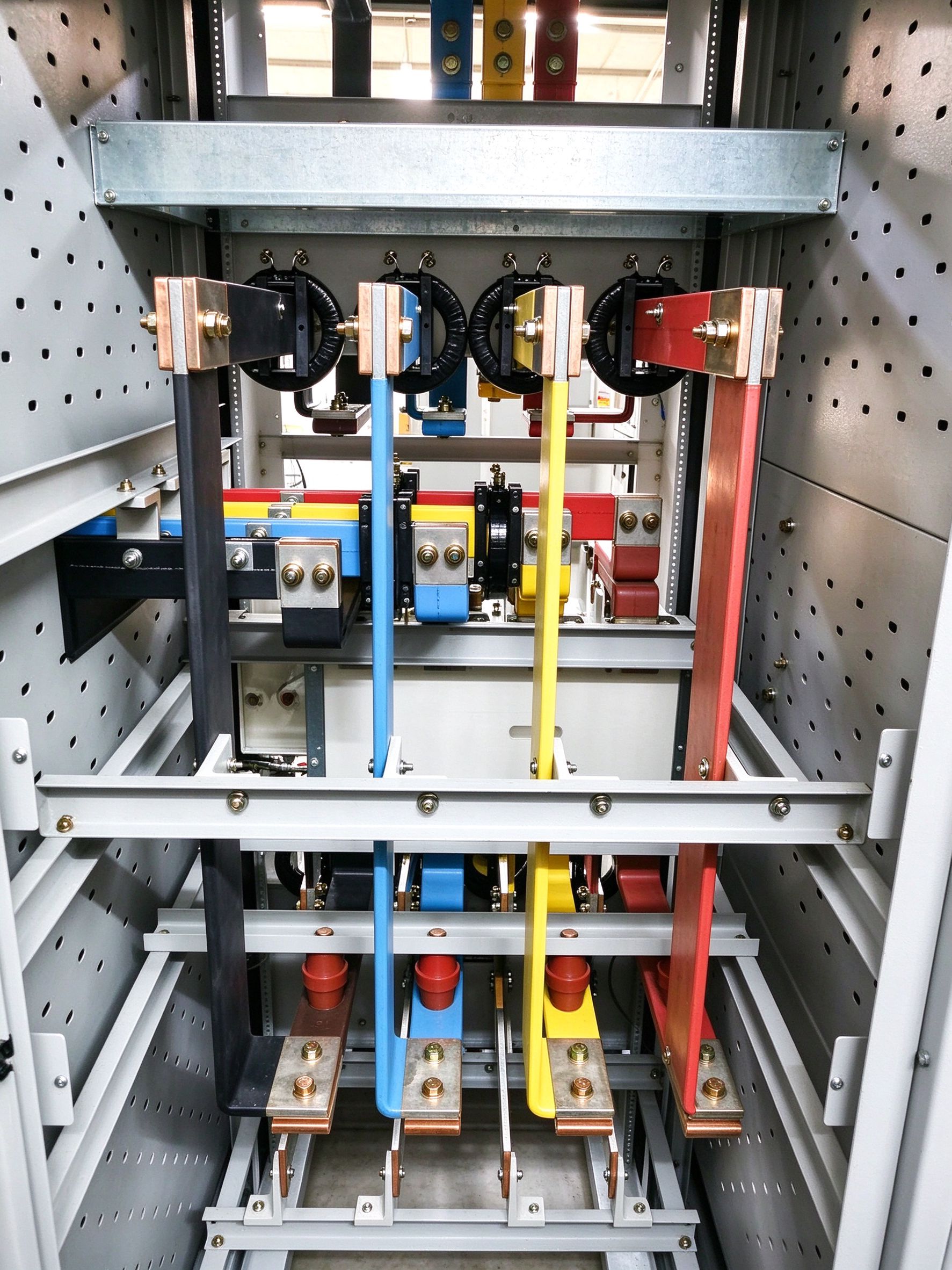
Two geometry choices deserve attention. Phase-to-phase air clearance matters: at 400 V, a minimum of roughly 20–25 mm of clear air between bare copper edges is the common starting point before barriers are added, and larger clearances raise the probability that a tracking arc will self-extinguish rather than bridge to the adjacent phase. The busbar support spacing also matters; an unsupported busbar long enough to vibrate during a through-fault can momentarily touch a neighboring bar and initiate exactly the arc the compartment is trying to prevent.
We cover the clearance and creepage sizing logic in a separate article on creepage and clearance design; the point here is that clearance, support spacing, and barrier placement are three inputs to the same IAC outcome, and weakening any one of them can invalidate the compartment effect.
Inside a compartment, several smaller design choices compound to suppress arc initiation in the first place. Phase barriers are rigid phenolic, polyester, or glass-reinforced plates fitted between adjacent phases, usually clamped to the support rail. They do not replace minimum air clearance — they add a physical obstacle that forces any developing tracking path to surface-flash along the barrier material, which is typically slower and easier to interrupt than an air gap.
Insulated busbar — either heat-shrink sleeved copper, epoxy powder coating, or laminated film wrap — removes the bare copper surface as the primary tracking surface. A laminated, insulated busbar such as the ones built into our LV switchgear busbar assemblies is particularly useful in dense cubicles, because the PET or Nomex dielectric prevents an accidental touching of adjacent bars during maintenance and reduces the chance that a dropped tool triggers a phase-to-phase fault. Insulation does not, however, make the busbar arc-proof: once the arc has started, the film burns away quickly.
Edge and burr control is the quietest contributor. A sharp sheared edge or a burr left after drilling acts as a local field intensifier, particularly at voltages above 690 V and in humid inland sites. Chamfering the punched holes, deburring the sheared edges, and controlling the surface roughness of tin-plated joints reduces partial-discharge inception and lowers the chance of a slow, creeping breakdown that develops into a full arc. We cover the diagnostic side in partial discharge monitoring guidance; the manufacturing-side checklist lives on our quality and inspection page.
Most internal arcs do not start at a carefully designed bend; they start at a bolted joint that has loosened in service, or at an insulating support that has cracked and begun to track. Busbar bolts on 400–1000 A joints should be torqued to the supplier's specified value and marked with a witness paint line, so a loosening bolt is visible on an infrared or thermographic walk-down. Lock washers alone are not adequate on high-current joints in vibrating environments; spring-steel lock nuts, prevailing-torque nuts, or welded stops are the usual choices.
The insulating support that carries the busbar is the second weak point. A generic nylon or PA66 standoff will soften at temperatures well below what an internal arc produces, and once it loses mechanical strength the busbar drops onto the cabinet floor. Arc-resistant supports are molded from polyester BMC, DMC, or epoxy resin with a classified glow-wire resistance (typically ≥ 960 °C) and a tracked erosion resistance that lets them survive the arc without collapsing the busbar. When you specify replacement supports for an existing switchgear line, confirm the glow-wire value, not just the color.
Thermal cycling, short-circuit duty, and bolt relaxation all interact on the same joint. Our article on vibration and bolted-joint design walks through the fastener selection logic; for IAC-sensitive cabinets, the joint should be specified once, and the torque, the lock device, and the insulator material should all be called out on the same detail drawing.
IEC 61641 defines what counts as a pass. The test is not only about the enclosure surviving; it is about a list of observable conditions on indicator gauze, door hardware, and internal maintainability. The table below is the checklist a third-party lab will walk through after the arc is extinguished and the cubicle has cooled.
| Criterion | Pass condition | Common failure |
|---|---|---|
| Indicator cotton gauze | Not ignited on any tested face | Gauze burns from hot gas jet at door seam |
| Enclosure covers and doors | Doors and covers remain closed, or open only in controlled direction per design | Door latch pops; cover flies off |
| Detached parts | No parts projected outward in the direction of standing personnel | Vent flap detaches; busbar support collapses |
| Internal maintainability | Busbar and functional units remain accessible; barriers not displaced beyond repair | Phase barrier melts and falls onto live parts |
| Separation from adjacent compartments | Arc does not propagate to adjacent cubicles | Flame passes through unsealed gland plate or bushing |
Note that the cabinet is not required to be undamaged. Some deformation, paint burn, and minor local melting of non-functional parts is expected and allowed, as long as the listed pass conditions hold. Customers should not ask for an \"undamaged after arc\" acceptance criterion — that is not what the IAC test demonstrates. What they should ask for is the test certificate, the photo record of the indicator gauze on each face, and the as-tested drawing so that the as-built cabinet matches the as-tested one.
This is the most common point of confusion on engineering drawings, and it is worth separating the two ideas cleanly. IEC 61439-1 IAC describes the behavior of the equipment during an internal arc: the cabinet contains the event, the hot gas is routed through the vent, and standing personnel outside the cabinet on accessible sides are not burned by indicator gauze ignition. It does not calculate an incident-energy number at a working distance, and it does not tell a maintenance engineer what PPE to wear while racking a breaker.
IEEE 1584-2018 and NFPA 70E describe the personnel side: the predicted incident energy in cal/cm² at a working distance (typically 450 mm for LV switchgear), the corresponding arc-flash boundary, and the required PPE category for a worker performing energized work. These calculations assume the arc happens regardless of whether the enclosure is IAC-rated; an IAC-rated cabinet still produces an arc inside it, and a worker opening the door before the cabinet is fully de-energized and verified can still be exposed.
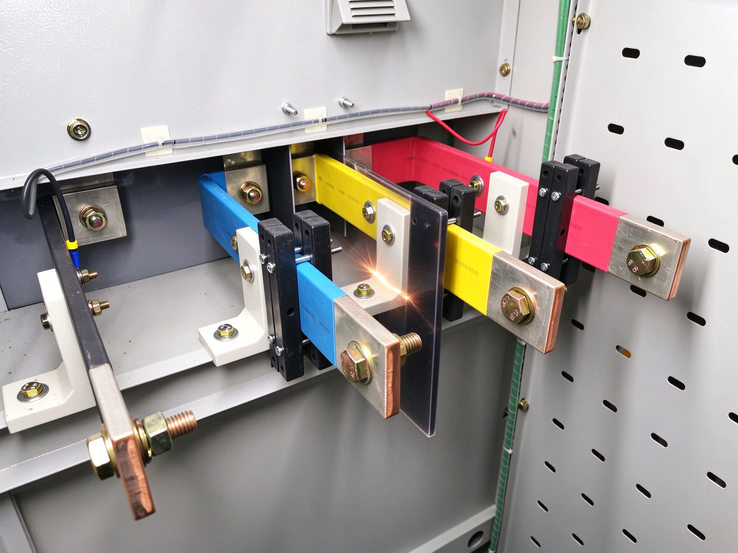
A practical reading: an IAC-rated enclosure reduces the probability that an internal arc becomes a room-level fire or a projection injury, but it does not by itself set the arc-flash boundary. You still need an IEEE 1584 study on the specific system, and you still need the worker to wear the PPE the study dictates. The two standards are complementary, not interchangeable. Buyers who want both usually write \"IAC-AFLR, 30 kA/1 s per IEC 61439-1 / IEC 61641, plus IEEE 1584 incident-energy study delivered at FAT\" on the specification.
Specifying IAC on a drawing is straightforward once the four fields in section 3 are filled in. A clean clause reads: \"Low-voltage switchgear assemblies shall comply with IEC 61439-1:2020 and shall be internally arc classified IAC-AFLR at 30 kA for 1 s, tested in accordance with IEC 61641 with the arc initiated in both the horizontal busbar compartment and the cable compartment. Type-test report from an accredited third-party laboratory shall be submitted at FAT. As-built drawings shall match the tested configuration.\"
Three additions are worth making. First, state the installation boundary: if the cabinet will be wall-mounted on the rear, a B or C side rating may be acceptable, but the rear of the cubicle must then be bolted directly to a solid wall, not left exposed in a corridor. Second, require the exhaust ducting layout to be approved as part of the submittal, so the as-installed vent path matches the tested path. Third, call out the busbar compartment details: minimum phase-to-phase clearance, presence of phase barriers, insulator glow-wire class, and fastener torque values. These are the details our engineering team typically reviews with a customer when they send a drawing for a quote.
For projects where the upstream fault level is still being finalized, write a placeholder Iarc value and require the bidder to quote options at 16 kA, 30 kA, and 50 kA. The incremental cost of stepping from 30 kA to 50 kA is usually small relative to the cost of a post-commissioning upgrade, and it protects you if the utility later raises the transformer impedance fault contribution. We discuss the related specification-side checklist in our busbar make-vs-buy guide.
A laminated or insulated busbar supplier does not, by itself, deliver an IAC-rated switchgear assembly. The IAC rating is a property of the assembled cubicle: the sheet-steel enclosure, the door latching, the vent flap, the compartment barriers, the supports, and the busbars all have to work together. What the busbar supplier does control is the part of the arc-initiation risk that sits on the copper itself: edge quality, insulation continuity, joint flatness, and support spacing.
At SHANYUAN, we work with switchgear builders and EPC contractors to design busbar sets that are compatible with their IAC-tested enclosure platform: tin-plated C11000 copper, deburred and chamfered edges, PET or Nomex insulation sleeves to the customer's barrier layout, and support drilling patterns that match arc-resistant insulator blocks. We do not issue an IAC certificate on behalf of the enclosure; that remains the assembly vendor's type-test responsibility, witnessed by an accredited lab per IEC 61641. We can, however, support that third-party test program by supplying representative busbar samples, providing installation drawings, and attending the test as observers if requested.
Two practical notes for buyers. First, when the upstream project is a behind-the-meter industrial load or a pulsed-power research installation, the available fault level and the maintenance access model differ from a standard commercial switchroom, and the IAC side selection should be re-checked rather than copied from a previous project. Second, for sites where the load is shifting from fossil process heat to electric, as in our industrial electrification case notes, the incoming feeder often sees a one-step fault-level increase, which is the moment to revisit whether the existing IAC rating still covers the upgraded installation.
Action items before your next RFQ: confirm the upstream prospective short-circuit current, choose the accessible-side rating that matches the physical installation, require both busbar-zone and cable-zone test points, and ask the switchgear vendor for the type-test certificate number and the as-tested drawing. Bring the busbar detail drawing into that conversation early; the joint between the insulated busbar and the compartment barrier is where most field arc events actually start.
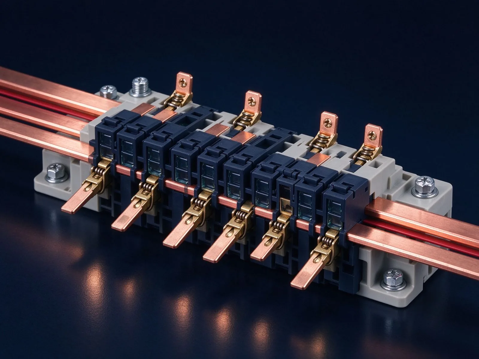
A short circuit is the busbar's worst moment: tens of kiloamps peak, forces in kilonewtons
Read article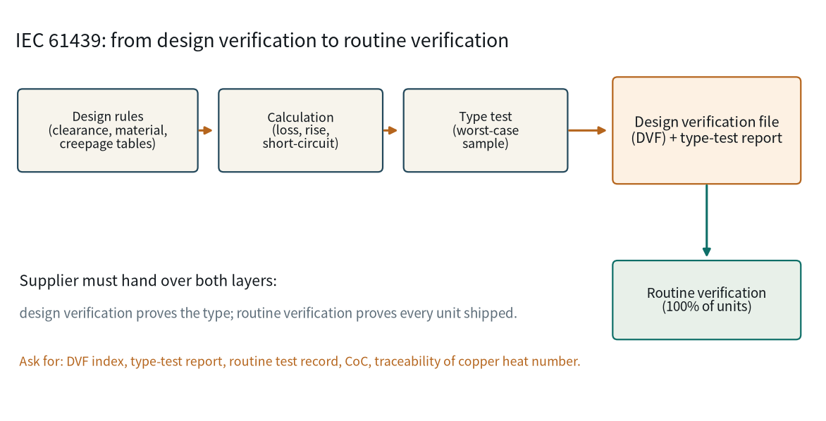
IEC 61439 governs the assembly, not the copper bar. That is exactly why busbar suppliers a
Read article
Nadia Rahman is a quality and compliance engineer with 9 years in electrical-component quality systems. She manages SHANYUAN's ISO 9001 and IATF 16949 programmes, incoming and outgoing inspection, and UL/IEC compliance documentation. She holds a B.Sc. in Industrial Engineering from the Universi
Send the current profile, voltage class and terminal types — our engineers reply within one business day.
