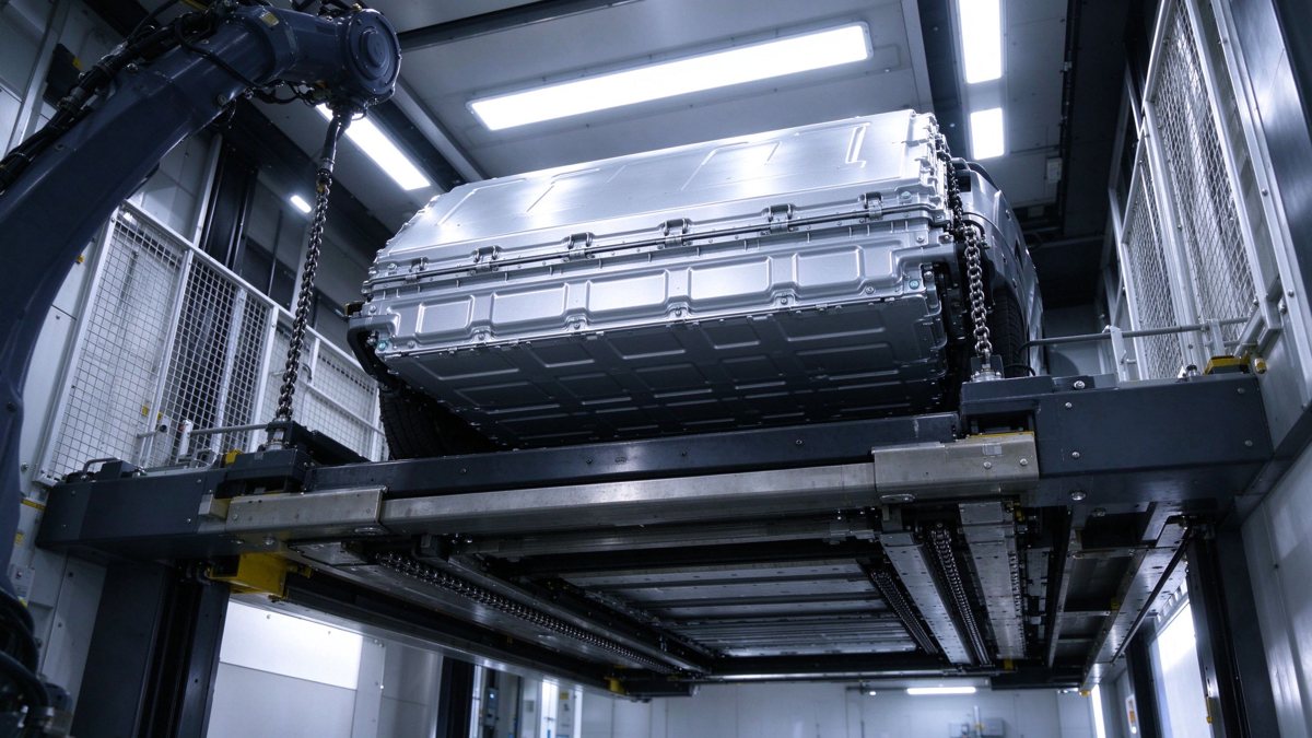
Battery swapping stopped being a niche experiment in China this year. With more than 2,520 stations in 200 cities by late September 2026, the equipment inside those boxes is now bought in series, maintained by field teams, and judged on uptime. The busbar is the part that carries the current nobody photographs: the pack interface, the rack DC bus, the charger link. Its design brief is different from a vehicle busbar because the joint is opened and closed by a machine, several times a day, for a decade.
Battery swapping stopped being a niche experiment in China this year. With more than 2,520 stations in 200 cities by late September 2026, the equipment inside those boxes is now bought in series, maintained by field teams, and judged on uptime. The busbar is the part that carries the current nobody photographs: the pack interface, the rack DC bus, the charger link. Its design brief is different from a vehicle busbar because the joint is opened and closed by a machine, several times a day, for a decade.
First published 6 November 2026 · Last updated 12 November 2026
This page is an annual rolling data page: the 2026 edition, refreshed once a year as new market data is published.
CATL's Choco-Swap network reached 2,520 stations across 200 cities and 31 provincial regions by 29 September 2026, according to company statements reported that month, with a target of roughly 3,000 stations and 4,000 combined charge-and-swap sites by the end of 2026. Independent coverage in October 2026 put nearly 20,000 batteries into circulation through the same network. Those figures matter to a component supplier for one reason: a station that swaps 40 to 80 packs a day accumulates 15,000 to 30,000 mating cycles a year on the same copper interface.
A vehicle busbar sees one assembly event at the factory. A station busbar sees a mechanical event every twenty minutes. Design assumptions built for the first case — a torqued bolted joint, a crimped lug, a soldered flex — do not survive the second without being re-examined.
Four current paths exist in a typical station, and each has a different duty. The pack interface carries the full charge or discharge current for the duration of a session, typically 200–600 A at 400 V or 800 V class. The rack DC bus distributes between parallel charger bays and runs continuously. The charger-to-bus link carries rectified output with switching ripple. The auxiliary and control path is small but must stay clean.
Because the pack interface is the only path that is physically re-made by the machine, it dominates reliability. A 1,000 A continuous rating on paper is irrelevant if the contact pair develops 50 µΩ extra resistance after 8,000 cycles; at 500 A that is 12.5 W of heat in a joint the size of a thumb, sitting inside a cabinet that already has charger losses. Sizing therefore starts from contact resistance growth, not from ampacity tables alone. Our ampacity chart gives the steady-state baseline; the cycling margin has to be added on top.
The summing bus is where a station differs from a charger. A site with four 120 kW bays drawing from a common 400 V bus can pull roughly 1,200 A when every bay is at full output, and the busbar has to carry that sum through a single laminated run before it splits again at the bay terminals. Designers usually split the bus into two or three segments with a bolted joint between them, which keeps each moulding small enough to press and gives the field team a serviceable break point. The catch is that every bolted joint in the DC path adds a resistance element that grows with cycles, so the segment count is a reliability decision as much as a manufacturing one.
Load sharing also decides the thermal profile. Bays rarely peak together, and a station controller that staggers bay output can hold the bus at 60-70% of its sum rating for most of the day. When that controller logic is not yet fixed at the design stage, the bus should be sized for the worst case rather than the average, because the software will be tuned later and the copper cannot be re-sized.
The move from 400 V to 800 V pack architectures doubles the working voltage without doubling clearance. Creepage and clearance distances inside a swap cabinet are constrained by the mechanical envelope of the pack tray, so designers end up trading insulation thickness against air path. Laminated busbars help because the dielectric is bonded to the conductor and the layer-to-layer gap is fixed by the film, not by assembly tolerance.
What does not help is assuming the vehicle-side rules apply. A station cabinet is a low-voltage assembly under IEC 61439-1, and its insulation coordination has to be verified at the assembly level, including the pollution degree of a roadside enclosure that opens to the sky several times an hour. Our design guide covers the clearance arithmetic; the practical addition for swap stations is a dust and humidity allowance that assumes the enclosure is not sealed.
The insulation stack for an 800 V DC link is not simply a thicker film. At that working voltage the field across a thin dielectric is high enough that partial discharge inception becomes the governing limit rather than breakdown voltage, and a void of a few tenths of a millimetre inside a bonded laminate can sustain discharge for years before it fails. That is why 800 V station bars are usually built with 0.2-0.5 mm of dielectric per layer pair, potted edges at the terminals, and a partial discharge acceptance test rather than a hipot-only test.
The second constraint is creepage across the surface of the bar where it passes a metal bracket. A polluted surface, which a roadside cabinet will have, reduces the effective creepage by a third or more compared with a clean laboratory sample. Adding a rib or a coated end section is cheaper than adding air distance inside a fixed enclosure, and it is the measure most often missed when a 400 V design is scaled to 800 V.
Swap stations rarely idle in dense urban networks. A station serving ride-hailing fleets may run 20 hours a day, with charger bays at 60–80% of rated output and cabinets at 45–55 °C internal ambient in summer. Under those conditions a busbar sized to a 30 °C temperature rise at nameplate current will sit well above its design point.
Two practical consequences follow. First, current density for natural convection inside a cabinet should stay near 6–8 A/mm² for copper rather than the 10 A/mm² that looks acceptable on a bench. Second, the thermal path from bar to enclosure matters as much as the bar itself; a laminated bar bolted to a painted panel conducts heat into a poor sink. See thermal management for the interface resistance numbers that decide whether the cabinet or the bar is the bottleneck.
A useful sanity check at the design stage: take the bar current, the copper section, the cabinet internal ambient and the measured rise, and compare the result against the terminal limit in the assembly standard. A 30 K rise on a bar in a 50 C cabinet reaches 80 C at the conductor, which leaves very little margin at the terminal where the contact resistance adds its own few watts. If the numbers do not close, the cheapest fix is usually airflow rather than copper: a filtered fan moving 200 m3/h through the cabinet can drop the internal ambient by 8-10 K, which buys more thermal margin than adding 20% to the bar section.
A spring-loaded or clamped pack interface loses normal force slowly. Tin plating on copper oxidises and frets; each cycle removes a little more of the soft layer and exposes asperities that then cold-weld and tear. The measurable signature is a rising milliohm reading, not a visible defect. Field teams that only check for discoloration will miss the first two-thirds of the degradation curve.
Acceptance criteria should therefore be written as a resistance window at a defined test current, measured at incoming inspection and re-measured at 5,000 and 15,000 cycles. A joint that starts at 20 µΩ and reaches 40 µΩ is still electrically acceptable but has consumed half its thermal margin. Our connection design note explains how to specify that window without forcing the supplier into an unrealistic first-article number.
Fretting is the mechanism behind most of that growth. Every mating cycle allows a microscopic relative motion between the two contact surfaces, driven by thermal expansion and by the mechanical tolerance of the clamp. The oxide that forms in the fretted zone is harder and less conductive than the bulk tin, and it accumulates in the contact patch rather than being wiped away. Silver plating resists fretting better than tin because its oxide is conductive, which is why high-cycle interfaces often specify a silver or silver-alloy finish despite the cost. Wipe distance, the small sliding motion designed into a connector during mating, is the countermeasure: it breaks through the oxide on each cycle instead of letting it build.
The pack tray is lifted, aligned, clamped and released by a mechanism with hydraulic or servo actuation. Shock loads transmit through the tray into the interface hardware, and the busbar sees them as bolt preload variation. A joint that passes a static pull test can still loosen under 20,000 clamp events if the bolt is not preloaded against a spring or a Belleville stack.
For station hardware we recommend specifying a prevailing-torque check at every service interval and a witness mark on the fastener, plus a thread-locking method that survives 120 °C. Where the interface is a connector rather than a bolted joint, the retention force belongs in the drawing, not in a catalogue. The connector selection guide sets out the force and wipe requirements that make a connector reliable under repeated mating.
Preload loss is calculable. A bolted joint with a 12 mm steel bolt at 60 Nm carries roughly 45 kN of clamp load; thermal cycling between the aluminium tray and the copper bar can relax 10-20% of that over a few hundred cycles as the materials creep and the joint beds in. A Belleville washer stack restores 30-50% of the lost preload because it stores elastic energy over a longer travel, and it also gives the inspector a visible gap to check. In stations that run 20 hours a day, the joint is thermally cycled every time a pack is swapped, so the relaxation happens faster than in a static installation.
Three documents frame the design. IEC 61439-1 governs the assembly: temperature rise verification, dielectric verification, short-circuit withstand and clearance rules. IEC 61851-23 covers the DC charging system that sits inside the cabinet. GB/T 40032 addresses battery swap safety for the mechanical and electrical interface. None of them specifies a cycle life for a busbar joint; that has to be written into the purchase specification as a station-level requirement.
This gap is where most supplier disputes start. A fabricator can certify a bar to IEC 61439-1 and still deliver something that fails at 10,000 cycles, because the standard tests the assembly once, not the duty. Write the cycle requirement, the resistance window and the inspection interval into the drawing package. The standards library links the clauses you need to cite.
Copper is the dominant material cost in a station busbar, and station builders are under pressure to reduce bill of materials as networks scale from hundreds to thousands of sites. The temptation is to trim section to the nameplate current. That trade works until the first summer of overload, then returns as warranty claims that cost more than the copper saved.
A more defensible approach is to hold section and reduce cost elsewhere: fewer layer transitions, tighter nesting to cut scrap, standardised widths across charger platforms. Copper content per station is roughly fixed by physics; fabrication yield is where a supplier can genuinely compete. Our copper versus aluminium comparison explains why aluminium is not a straightforward substitute at this current density and enclosure size.
An RFQ for swap-station busbars should state the duty, not just the dimensions. Minimum content: continuous and peak current per path; voltage class and pollution degree; ambient and internal cabinet temperature; expected mating cycles per year and design life; interface type (bolted, connector, welded); plating thickness and underplate; resistance window at test current; torque and retention requirements; dielectric test voltage and PD limit; documentation set.
Suppliers who quote only against a drawing will price the copper and ignore the duty. Suppliers who ask for the cycle count and the ambient profile are the ones who will engineer the joint. The sample-to-series path shows how to stage that conversation so the first article proves the process before volume is committed.
Two fields are routinely missing from station RFQs and both change the answer. The first is the number of mating cycles expected on the pack interface over the design life, not just per year; a station that runs ten years at 60 swaps a day is a 200,000-cycle joint, which is beyond what a standard connector datasheet covers. The second is maintenance access: whether a technician can reach the joint with a torque wrench in under five minutes, or whether the cabinet has to be de-energised and partly dismantled. Access decides whether the design can rely on periodic re-torque or must be maintenance-free.
Three tests belong on every station busbar: a contact resistance measurement at a defined current, a dielectric withstand with a partial discharge check for 800 V hardware, and a thermal cycle that reproduces the cabinet's daily swing. The first catches joint quality, the second catches voids in the laminate, the third catches loosening.
Cycle testing can be accelerated. A 500-cycle chamber run between −20 °C and +85 °C, with current applied during the hot dwell, exposes most plating and preload weaknesses. It is not the same as 20,000 mechanical mates, but it is a cheap filter before field trials. See partial discharge for the measurement setup and the limits that make a PD pass meaningful at 800 V.
Test current matters as much as the limit. A micro-ohmmeter that injects 1 A will read the constriction resistance of a few asperities and can look excellent while the joint is already partly separated. A measurement at 100 A, or at the rated current, heats the contact patch and reads the resistance the joint will actually present in service. Specify the test current, the stabilisation time and the temperature at which the reading is taken, otherwise two suppliers will report numbers that cannot be compared.
Across station designs we have reviewed, the failure ranking is consistent: loose or corroded pack interface first, laminate delamination at a bend second, cracked terminal shoulder third, and open fuse or contactor failures that get misattributed to the busbar fourth. Each has a different countermeasure.
Interface wear is solved with plating and preload, not with thicker copper. Delamination is solved with bend radius and press parameters, not with a different film. Terminal cracks come from over-torquing a shoulder that was machined too thin. The failure mode selection guide maps each signature to the design decision that prevents it, which is useful when a station operator reports a symptom without a teardown.
Bolted laminated bar: lowest cost, best thermal spread, requires torque control and periodic re-check; suited to rack DC bus and charger links. Connectorised bar: fastest field replacement, higher unit cost, needs a defined mating force and wipe; suited to pack interface where service access is constrained. Welded flex section: absorbs alignment error, no fasteners at the joint, but not serviceable in the field; suited to fixed internal links. Solid bar with insulation boot: cheapest for low layer counts, weakest dielectric consistency, acceptable only where the air path is generous.
The matrix is a starting point, not a rule. A station with 60 swaps a day and a 10-year design life should weight serviceability above unit cost, because a truck roll costs more than the hardware. A low-utilisation station can accept the bolted bar and the inspection interval that comes with it.
Two adjacent questions usually come up in the same meeting: how the 800 V insulation stack is verified, which we covered when the SF6-free switchgear transition pushed medium-voltage clearances wider, and how the per-unit cost compares across a multi-year station roll-out, which the MOQ and total cost framework sets out in numbers.
Network growth from 2,500 to 4,000 sites in a year changes procurement from project buying to platform buying. Platforms standardise the interface, which is good for cost and bad for lock-in; the busbar drawing becomes the de facto specification that every station inherits. Getting the duty cycle, resistance window and plating stack right at platform level is cheaper than fixing them site by station.
For suppliers, the differentiator is not copper price. It is the ability to document cycle performance, hold a resistance window over 15,000 mates, and ship consistent laminate quality at volume. Buyers should test that capability before they scale, not after. If you are specifying a station interface now, the engineering contact route gets the duty profile reviewed against our standard stack before a drawing is frozen.
Another consequence of platform standardisation is that the busbar drawing becomes a shared asset between station generations. When a network moves from a 400 V platform to an 800 V one, the mechanical envelope usually stays close to the original because the pack tray and the lift mechanism are expensive to change. The insulation stack has to be re-qualified inside that envelope, which is exactly where a supplier with laminate experience adds value: the fix is often a thinner, higher-performance dielectric and a redesigned edge, not a bigger cabinet.
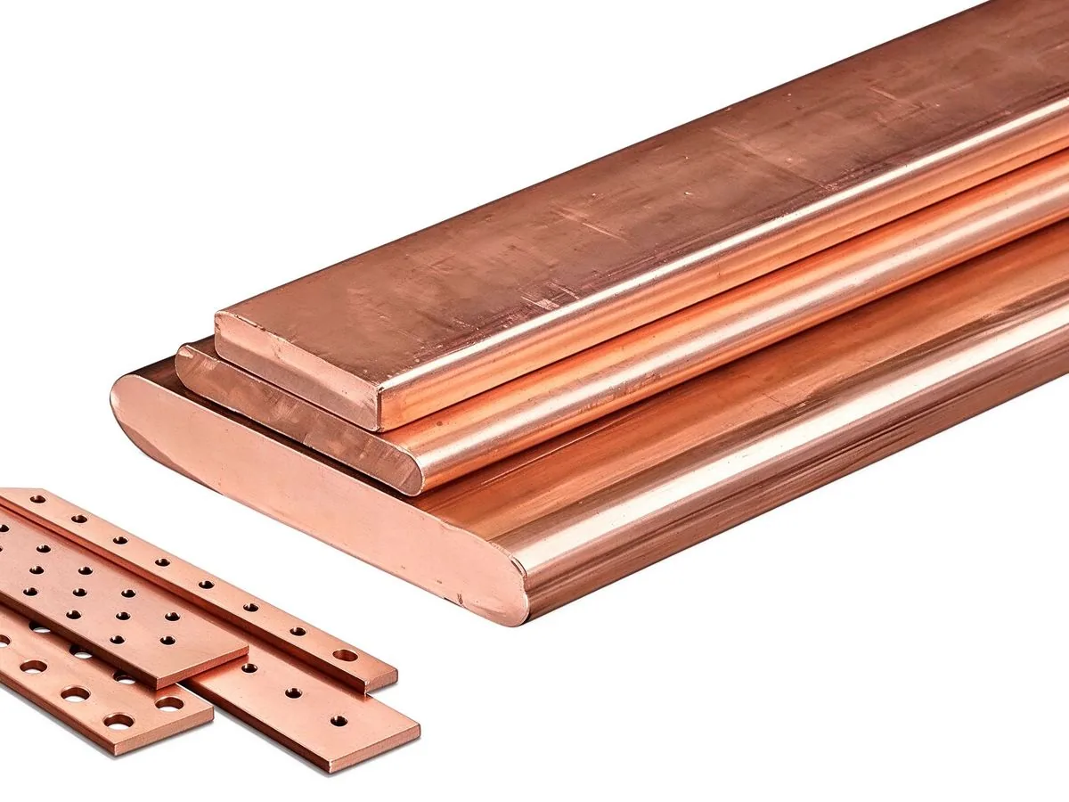
MCS moves from pilot to fleet scale in 2026: 1 MW+ charging at 1250 V and up to 3000 A mak
Read article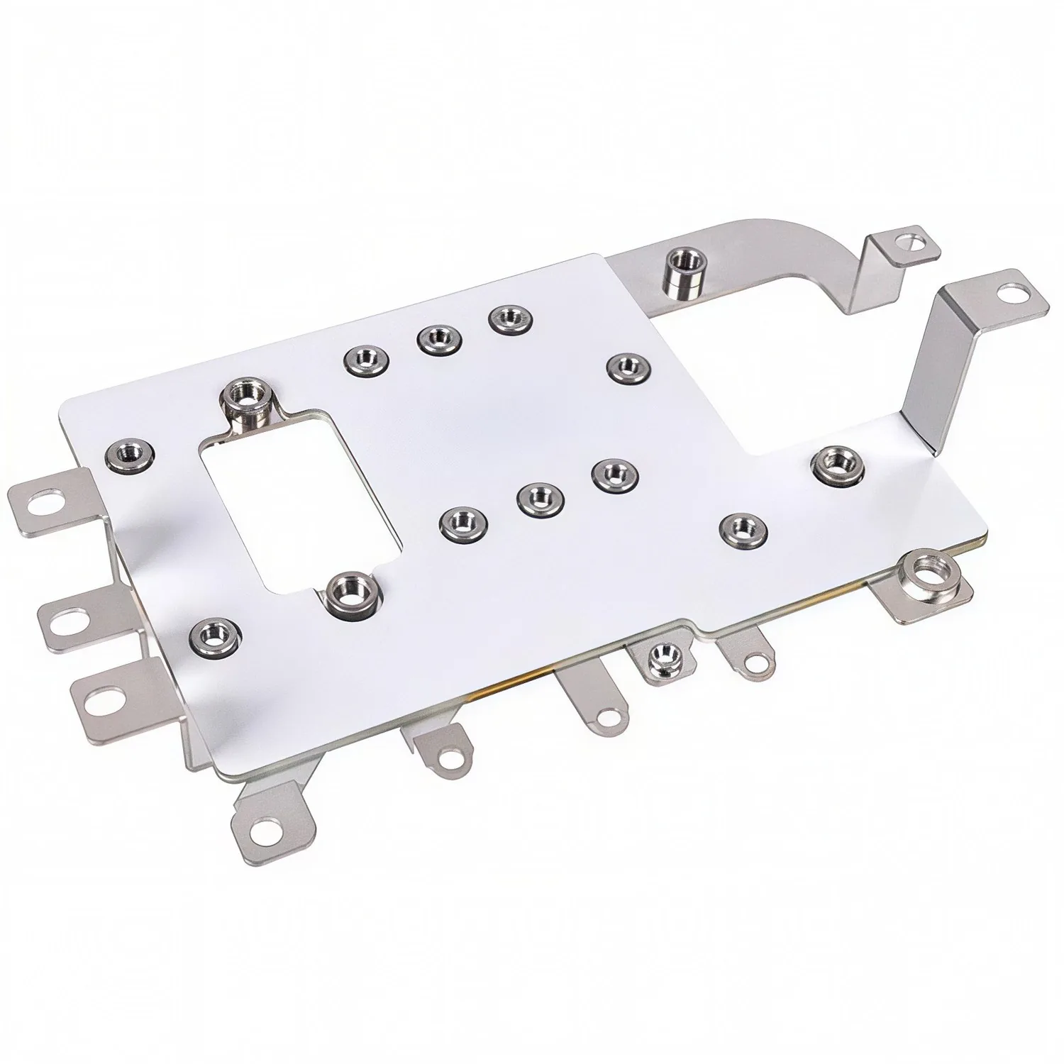
A joint that is tight is not the same as a joint that is correct. Torque windows, pull lim
Read article
Elena Vasquez is a power electronics application engineer with 10 years of experience integrating laminated busbars into EV inverters, charging systems and energy-storage PCS. She specializes in low-inductance DC-link design, EMC behaviour and converter packaging, and holds a B.Sc. in Electrical Eng
Send the current profile, voltage class and terminal types — our engineers reply within one business day.
