Megawatt charging is crossing from demonstration projects into commercial fleet operations. The Megawatt Charging System (MCS) specification - a DC interface for heavy-duty battery electric vehicles rated at up to 1250 V and 3000 A - moves charging from a single-truck afternoon stop to a depot throughput problem, and every megawatt class charger now has to be engineered around thermal density, low inductance and repeatable, high-current interconnection. That is where the laminated busbar stops being a commodity part and becomes a core element of the charging power stage.
Megawatt charging is crossing from demonstration projects into commercial fleet operations. The Megawatt Charging System (MCS) specification - a DC interface for heavy-duty battery electric vehicles rated at up to 1250 V and 3000 A - moves charging from a single-truck afternoon stop to a depot throughput problem, and every megawatt class charger now has to be engineered around thermal density, low inductance and repeatable, high-current interconnection. That is where the laminated busbar stops being a commodity part and becomes a core element of the charging power stage.
In 2026 the Megawatt Charging System is no longer a test-bench concept. Scania, Daimler Truck, Volvo Group and other members of the CharIN-backed MCS initiative have moved from interoperability demonstrations to production charging posts, and heavy-duty OEMs are quoting depot layouts in which a 700 kWh battery can be replenished from 20% to 80% in roughly 45 minutes at around 1 MW. The engineering consequence is blunt: a megawatt-class DC link operates at currents no air-cooled connector family has ever handled in continuous duty. Industry data collected through 2026 put the MCS envelope at 1,250 V DC and up to 3,000 A per coupler, with power classes of 1 MW and above, and early deployments already targeting 1.5-3.75 MW per pedestal.
For component suppliers the shift matters because charging infrastructure is now being designed to the same discipline as traction inverters: power density per litre, junction temperatures, and predictable impedance in the high-current path. The DC link between the grid-side converter and the vehicle inlet - and equally the internal interconnects inside each charging power module - must carry thousands of amps continuously while remaining manufacturable at automotive-grade quality levels.
The MCS interface defined by the CharIN specification family sits at 1,250 V DC (with system voltages trending higher as the standard evolves) and a rated current of 3,000 A at the connector. Combined, these two numbers place every conductor in the path - cable, coupler contacts, fuse bus, contactor bus, and the power module busbars - under simultaneous electrical and thermal stress. At 3,000 A, resistive (I²R) losses in a copper path that might be acceptable at 300 A become kilowatts of heat concentrated in a hand-sized connector zone.
The MCS ecosystem therefore relies on liquid-cooled connectors, liquid-cooled cables, liquid-cooled power modules and dedicated coolant circulation units. In the cable assembly, J3271/3-style designs treat liquid cooling as the mandatory design basis rather than an option. For busbar suppliers the practical implication is that a megawatt-class charging power module no longer has a single cold point: the module DC bus is expected to shed heat through conduction to a cold plate while carrying 600-1,000 A per phase.
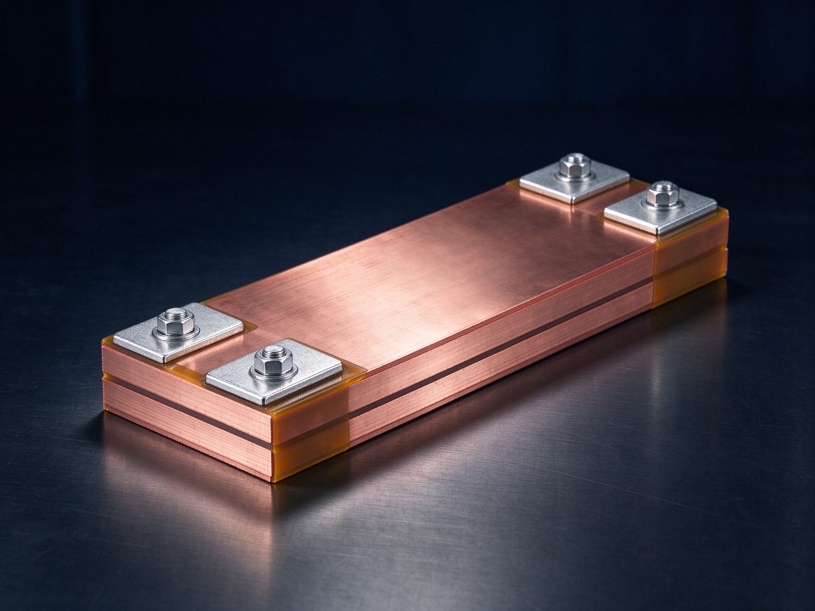
At currents above roughly 1,000 A, the I²R heat generated in cables, connectors and busbars exceeds what passive or forced-air designs can safely dissipate. Industry guidance published across 2026 is consistent: liquid cooling is not optional at megawatt scale. The loss budget works out quickly - a 0.5 mΩ connection at 3,000 A dissipates 4.5 kW, and the busbar itself contributes additional losses proportional to its resistance and skin-effect penalty at DC ripple frequencies.
This drives three busbar design responses. First, cross-sections are sized for both current density and thermal gradient, not just ampacity. Second, the dielectric and stack-up must survive the temperature gradient between a liquid-cooled cold plate and the switching devices. Third, the busbar layout must minimise loop inductance so that high di/dt events in the charger power stage do not create destructive voltage overshoot. Laminated constructions, with their interleaved conductor layers and thin dielectrics, directly address the third point while offering a flat, stackable geometry that conducts heat to a cold plate.
Inside a modern ultra-fast charging module the power flow runs from the AC/DC front end through a DC bus, into isolated DC/DC stages, and out to the vehicle. At 1250 V systems, each stage needs low-inductance DC links to keep switching-node overshoot inside the silicon's safe operating area. A laminated busbar with interleaved positive and negative layers achieves inductance reductions of 5-20x compared with conventional cabling, which is why essentially every high-power charging platform announced in 2025-2026 specifies laminated DC-link busbars for the inverter and DC/DC stages.
The same component carries the module's high-current distribution: input bulk capacitance, output filtering, contactor and fuse positions are bussed on a single laminated assembly instead of a bundle of cables. That consolidation is what lets a 1 MW pedestal fit its electronics into a cabinet the size of a conventional 350 kW station. For EV inverter laminated busbars and inverter DC-link busbar assemblies, charging infrastructure is now a volume application in its own right, not a niche.
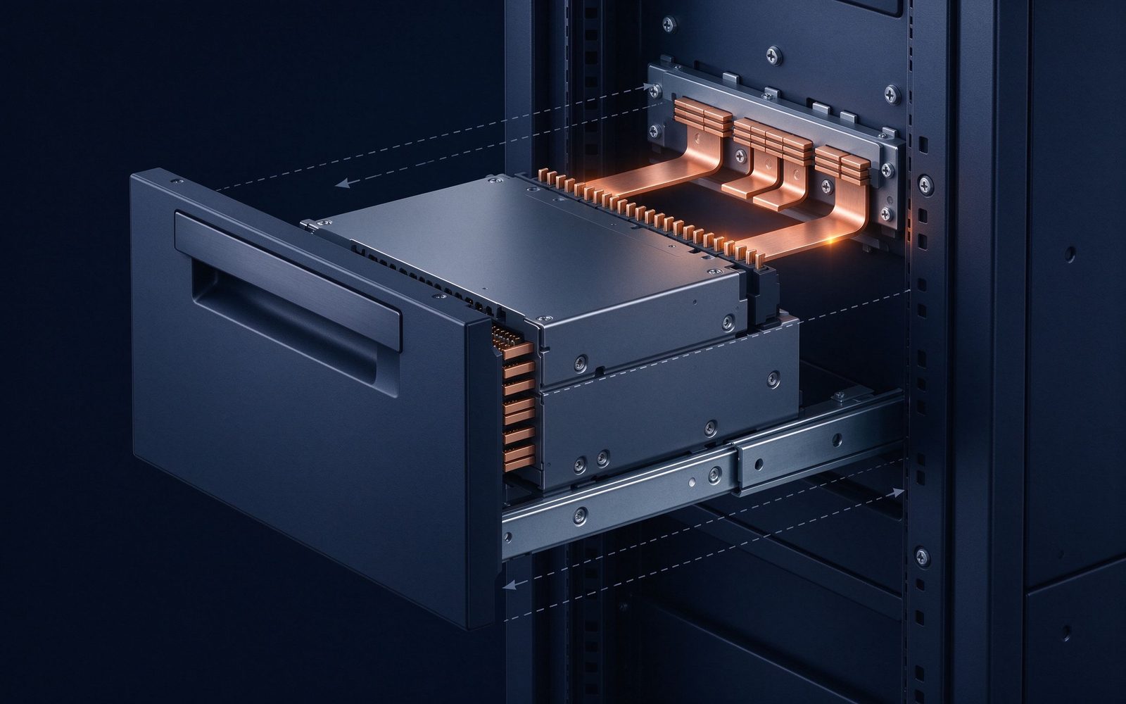
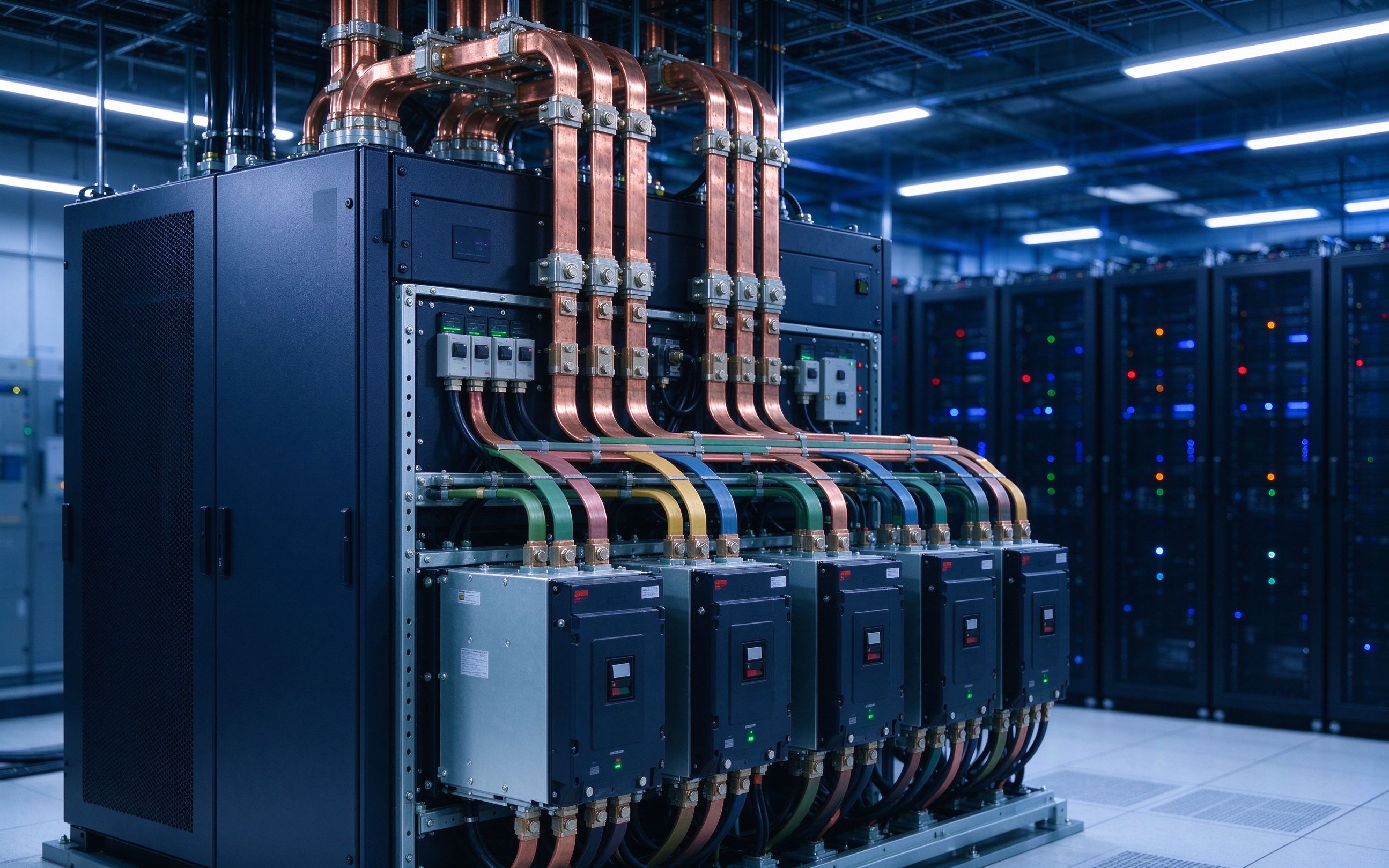
The IEA Global EV Outlook 2026 reports that the total stock of public charging points worldwide exceeded 7 million at the end of 2025, and that around 45% of newly installed chargers in 2025 were fast or ultra-fast (22 kW and above). Europe's public fast-charger share is climbing toward 30% by 2030 under the Stated Policies Scenario, and charging capacity across Europe is projected to reach roughly 115 GW by 2030.
The ratio that matters for component demand is average charging capacity per electric light-duty vehicle, which the IEA tracks as rising across all major markets. Every incremental kilowatt of average charging capacity translates into more high-current power stages - and therefore more laminated busbars, liquid-cooled interconnects and DC-link assemblies per charging point. The busbar content of an ultra-fast charger is small in mass but high in value and engineering content, which is why charging infrastructure has become one of the fastest-growing end-markets for laminated busbar manufacturers.
| Parameter | CCS (light-duty, typical 2025) | MCS (heavy-duty, 2026 spec) |
|---|---|---|
| System voltage | up to 1,000 V DC | up to 1,250 V DC |
| Rated current | 500 A (class) | 3,000 A |
| Power class | 350 kW | 1 MW - 3.75 MW |
| Connector cooling | air or liquid (optional) | liquid, mandatory design basis |
| Communication | ISO 15118 / DIN | ISO 15118-20, Plug & Charge, Ethernet |
| Target vehicles | passenger cars | trucks, buses, port & mine equipment |
The comparison clarifies why busbar suppliers see charging as a power-electronics market rather than a cable market: the thermal and impedance requirements of a 3,000 A path are identical in kind to those of a traction inverter DC link, just scaled up.
At 1 MW scale the charging power module dissipates its losses in a small enclosure, and the busbar is one of the few continuous metal paths available for spreading heat. Designers therefore evaluate busbar stack-ups not only on dielectric strength but on the thermal path: conductor thickness, edge cooling area, and the interface to a cold plate. Busbar thermal management practice for charging modules follows the same rules as traction applications - heat flows best where the copper is thick and the dielectric is thin, and every interface should be machined or plated to minimise contact resistance.
Material choices mirror EV practice: C11000 copper conductors, tin plating as the standard finish for corrosion resistance and stable contact resistance, and PET or Nomex dielectrics selected by voltage class and thermal class. For the 1250 V MCS envelope, insulation coordination follows the same logic as partial discharge requirements in high-voltage platforms: the dielectric must stay discharge-free at operating voltage plus margin, which in practice favours edge-filleted, void-free lamination rather than simple film wraps.
Charging pile and power module OEMs across Europe and Asia are converging on laminated DC-link assemblies for their 800 kW and 1 MW platforms. The pattern mirrors what happened in traction inverters five years earlier: cables and point-to-point wiring are replaced by a single laminated assembly that integrates bus capacitance, fuse positions and gate-driver wiring into one manufactured part. For custom projects, the custom busbar design service is where most charging customers start - defining voltage class, current, terminal map and cooling interface before committing to tooling.
The commercial logic is straightforward. A 1 MW pedestal represents tens of thousands of dollars of electronics per unit; a laminated busbar that removes 15 kW of avoidable loss and cuts assembly time is a design decision that pays for itself immediately. As fleet depots scale from 4 to 40 stalls, the component-level reliability requirement tightens correspondingly.
SHANYUAN builds laminated busbars for EV charging power modules with the same 17,200 m² manufacturing platform used for traction and industrial applications: 1-6+ layer stacks, C11000 copper, tin plating as standard, PET/Nomex/DLF dielectrics, and 30 °C-rise ampacity verified in house. The multi-layer insulated busbar family and high-current battery module busbars share the design rules that charging customers need, and our quality system supports PPAP-style documentation for series production.
Because charging hardware runs outdoors and unattended, we validate terminal torque retention, thermal cycling and insulation integrity as standard - the same disciplines covered in the DFM checklist and terminal connection guide.
The business case for MCS is depot throughput, and depot layouts expose a second set of busbar applications beyond the charging post itself. Fleet operators are installing on-site battery buffers and solar canopies, feeding a common DC bus from which multiple megawatt stalls draw power. That intermediate DC bus - typically 800-1,250 V with tens of metres of distribution - is increasingly realised as laminated or extruded distribution rails rather than bundles of individually routed cables.
Three design details dominate in depots. First, the DC bus must handle sustained near-rated current during simultaneous charging sessions, which drives conductor sizing toward the same 30 °C-rise logic used in power distribution systems. Second, the bus must tolerate repeated thermal cycling without loosening its bolted joints, making terminal torque retention and spring washers critical. Third, fault clearance matters: a bolted bus with a soft spot can arc at 1,000 A+ before a breaker opens, so joint design follows the principles in the terminal connection guide.
Grid connection is the other half of depot engineering. A 10 MW depot connects to the distribution network at medium voltage and typically steps down through transformers sized for charging peaks. Some operators add stationary storage to shave demand charges, which creates a second DC-link application identical in kind to grid-scale energy storage busbar systems. The component-level result is the same everywhere: more laminated DC links, more distribution rails, more low-inductance interconnects.
Unattended, outdoor, high-current charging hardware is a reliability problem by design, and the component qualification burden is shifting onto busbar suppliers. Charging OEMs now request the same evidence as traction customers: thermal cycling test data, insulation resistance at humidity, partial discharge behaviour at the operating voltage, terminal torque retention over temperature, and traceability back to material certificates. This is why SHANYUAN's quality system treats PPAP-style documentation as standard for charging series orders.
The relevant test framework converges on IEC 60664-1 insulation coordination and the high-voltage test suite - impulse, AC power-frequency, partial discharge and DC tests - applied to the module DC link exactly as it would be to a traction inverter busbar. Where charging adds a twist is the coolant loop: busbars mounted on or beside liquid-cooled cold plates must survive condensation, coolant leaks and dielectric surfaces wetted by glycol mixtures, which is where edge sealing and dielectric selection per dielectric selection guidance become safety-critical rather than cosmetic.
For customers, the practical checklist mirrors the DFM checklist: define the voltage class and pollution degree, state the cooling interface, specify terminal torque and maintenance intervals, and ask for test evidence before tooling commitment. The cost of a field failure in a megawatt depot is a stalled truck and a tow, which makes component-level discipline a direct commercial argument for laminated construction over field-assembled cabling.
Consider a concrete example: a 1 MW MCS pedestal serving a fleet depot. The grid connection feeds an AC/DC power stage rated 800 kW continuous with 1.25 MW peaks; the DC output runs at 1,250 V into a liquid-cooled distribution assembly; four independent DC/DC stages each handle 250-300 kW and are bussed on a laminated DC link with integrated bulk capacitance. The DC-link busbar for each stage carries roughly 200-250 A steady state with high switching ripple - an ideal case for a 2-layer laminated stack with interleaved power and return planes, tin-plated, rated for 30 °C rise at 40 °C ambient, and derated for the coolant-assisted enclosure.
The same pedestal contains a second busbar application that is easy to overlook: the fault-protection bus. Between the DC link and the vehicle inlet sit contactors, fuses and current sensing that must interrupt or isolate a megawatt-scale fault. The busbar carrying that path has to maintain low resistance (to avoid fault-let-through heating), clearances that survive the fault transient, and mechanical rigidity that survives repeated contactor operation. Laminated construction satisfies all three; the layout logic is covered in the power distribution guide and the mechanical rules in the DFM checklist.
At charging-class currents, terminals stop being an attachment detail and become a thermal design element. The connection between busbar and contactor, between busbar and the vehicle inlet, and between busbar and the cable lug must each hold its contact resistance stable across thermal cycling - which is why charging busbar terminals are specified with tin plating (or nickel where the coolant loop is involved), machined mating surfaces, and spring-loaded or torque-controlled fasteners. The terminal connection guide explains the stud-versus-blade decision; charging hardware adds two constraints: the connection must tolerate high di/dt without fretting, and it must be serviceable inside a cabinet where the coolant loop runs nearby.
Plating also carries the corrosion argument. Charging cabinets live outdoors, breathe humid air, and now integrate liquid coolant - a combination that attacks unplated copper surfaces. Tin plating provides the standard defence; where the coolant is a water-glycol mix, the busbar edge sealing becomes part of the dielectric system, as described in the insulation testing guide. For engineers specifying charging busbars, the practical list is: specify the plating and its minimum thickness, define torque and re-torque policy, and require the joint resistance measurement as a routine acceptance gate.
Rated connector current is 3,000 A at up to 1,250 V DC, with power classes of 1 MW and above; early systems target 1.5-3.75 MW per pedestal.
Above roughly 1,000 A the I²R heat in cables, connectors and busbars exceeds what forced-air can dissipate, so liquid-cooled cables, couplers and power modules are the design basis.
It provides a low-inductance DC link for the SiC power stages, consolidates capacitance/fuse/contactor distribution, and conducts heat to the cold plate - cutting assembly cost and improving reliability.
Partially - the voltage class and terminal strategy differ, but the same ampacity, dielectric and inductance disciplines apply; most charging customers start with a custom design review.
Continue with the day's companion articles: the PCS and DC-link trends in grid storage, the 2026 laminated busbar market outlook, or dive into engineering with insulation testing, thermal management and welding and joining.
BloombergNEF sees 158-188 GW of new energy storage in 2026. PCS platforms are climbing fro
Read article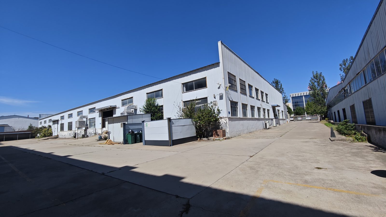
Multiple forecasters put the laminated busbar market near USD 1.0-1.06 billion in 2026, wi
Read article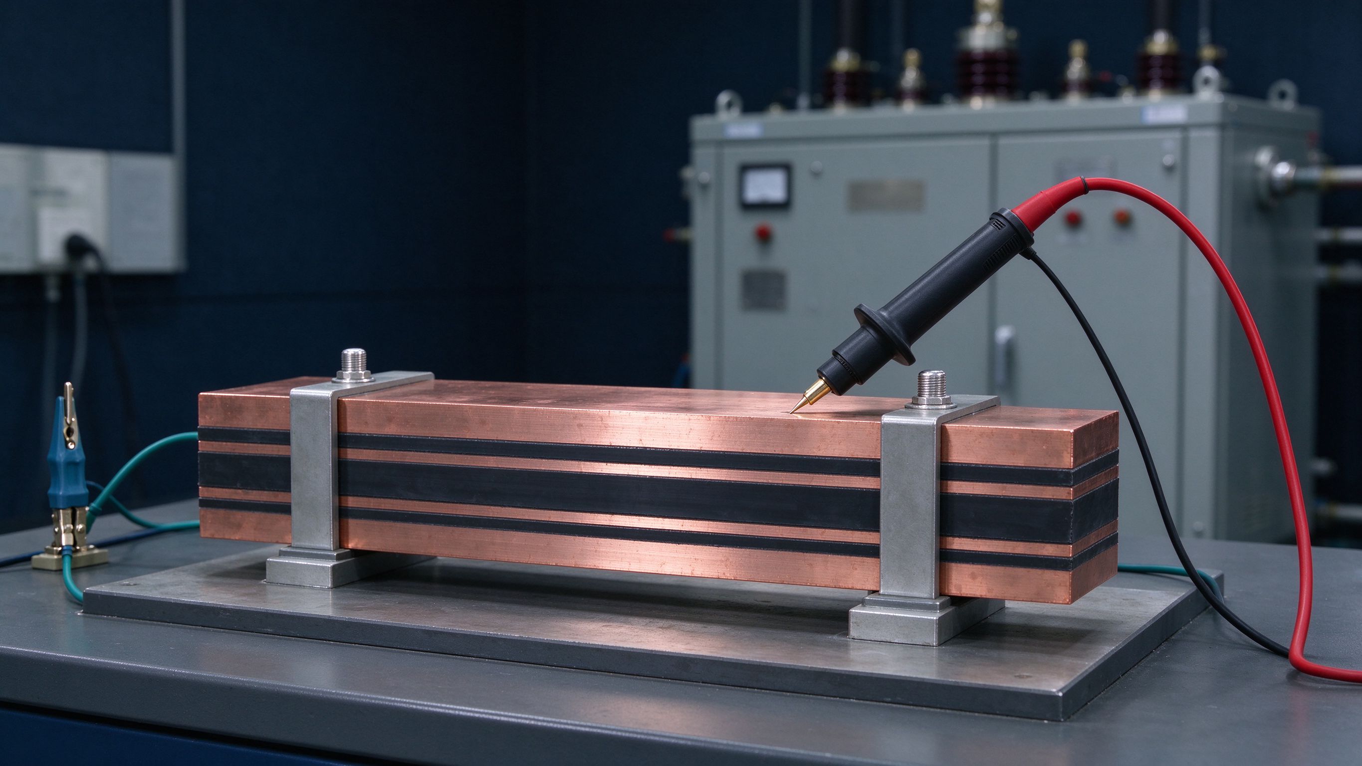
Insulation testing answers four questions: does it withstand rated voltage, does it discha
Read articleSend the current profile, voltage class and terminal types — our engineers reply within one business day.
Send drawings, current ratings and voltage class — DFM feedback and a quotation within one business day.
