On 1 January 2026 the EU stopped allowing SF6 in new medium-voltage switchgear up to 24 kV. The deadline had been visible for years, but it still arrives as a manufacturing problem rather than a policy one: SF6 gave designers roughly three times the dielectric strength of air and a self-healing arc environment. Without it, the copper inside the enclosure has to work harder. Clearances grow, tanks change shape, temperature rise budgets tighten, and the busbar becomes the component where those compromises show up.
On 1 January 2026 the EU stopped allowing SF6 in new medium-voltage switchgear up to 24 kV. The deadline had been visible for years, but it still arrives as a manufacturing problem rather than a policy one: SF6 gave designers roughly three times the dielectric strength of air and a self-healing arc environment. Without it, the copper inside the enclosure has to work harder. Clearances grow, tanks change shape, temperature rise budgets tighten, and the busbar becomes the component where those compromises show up.
First published 6 November 2026 · Last updated 12 November 2026
This page is an annual rolling data page: the 2026 edition, refreshed once a year as new market data is published.
Regulation (EU) 2024/573 replaced the earlier F-gas rules and set two dates that matter to switchgear designers. New medium-voltage equipment up to 24 kV may not be placed on the EU market with fluorinated greenhouse gases from 1 January 2026. Equipment between 24 kV and 52 kV follows on 1 January 2030. High-voltage equipment has a later path but the direction is the same.
The practical effect is that the 12 kV and 24 kV distribution classes — the volume of the market — moved to air, vacuum or g3 this year. ABB, Siemens Energy and Schneider Electric all publish SF6-free ranges for these classes; the engineering differences between them sit largely in how the busbar is arranged and cooled.
The scope matters as much as the date. The restriction applies to placing new equipment on the market, so a panel assembled before 2026 and held in stock can still be sold, but a new project specified after the deadline cannot use SF6 whatever its commissioning date. Service and maintenance of existing SF6 equipment remain permitted, and the recovered gas must be handled under the same regulation. For a switchgear builder that means two parallel product lines for several years, and two different busbar designs that share a factory.
SF6 is an electronegative gas: it captures free electrons and suppresses the avalanche that leads to breakdown. At typical switchgear pressures its dielectric strength is about three times that of air at the same gap. It also absorbs arc energy well and recombines after arcing, which is why the same gas could insulate and interrupt.
Remove it and two problems separate. Interruption moves to vacuum, which is a solved problem for medium voltage. Insulation does not have an equally cheap substitute: dry air needs higher pressure or longer paths, g3 mixtures need different handling, and solid insulation moves the field into a dielectric that cannot self-heal. Every one of those routes changes what the busbar looks like.
The physics explains why the substitute is hard. SF6 molecules capture free electrons to form heavy negative ions, which drift too slowly to start the next ionisation step. That is why the effective dielectric strength rises so sharply with pressure and why a 40 mm gap in SF6 holds what a 120 mm gap holds in air. Vacuum removes the gas entirely and relies on the mean free path being longer than the gap, which works well for interruption but requires the contacts to sit inside a sealed envelope that the busbar cannot easily enter.
In an air-insulated cubicle the busbar is back in open air, behind barriers, at atmospheric pressure. Phase-to-phase and phase-to-earth distances that were 40–60 mm in SF6 become 100–150 mm at 24 kV depending on pollution degree and impulse level. The bar geometry follows: narrower bars spaced further apart, more support insulators, longer creepage paths over insulated sections.
This is where the design work concentrates. A compact bar that fit the old tank now forces a larger enclosure, which changes shipping dimensions and floor space in a substation. When the enclosure cannot grow, designers raise the insulation level of the bar instead: thicker dielectric, more layers, field-grading at the ends. Our design guide sets out the arithmetic for both routes.
The clearance numbers are not the whole story. Air-insulated designs also have to control the field at the conductor surface, because a sharp edge or a burr raises the local field by a factor of two or three and starts corona well below the withstand voltage. That is why air-insulated busbars get rounded profiles, shielded ends and a surface finish free of protrusions, and why a bar that was acceptable in a gas tank often has to be re-machined for an air cubicle.
g3 and dry-air GIS keep the small footprint but change the internal environment. Dry air at 1.3–1.6 bar relative pressure restores much of the dielectric strength, but it also raises convective heat transfer inside the tank and changes the temperature-rise balance. g3 mixtures behave closer to SF6 but need tighter moisture control and different gas handling at the factory.
The busbar consequence is particle sensitivity. A free metallic particle that would sit harmlessly in SF6 can trigger breakdown in dry air at the same field strength, so busbar surfaces must be smoother, shield rings become mandatory at high-field points, and the factory has to prove cleanliness, not just withstand. Partial discharge measurement moves from a type test to a routine test on every tank. See partial discharge testing for the detection methods that work on a sealed unit.
Pressure is a design variable, not a fixed value. Dry air at 1.5 bar relative pressure roughly doubles the dielectric strength compared with atmospheric air, which recovers most of the compactness lost without SF6, but it also raises the dew point requirement: moisture that would be harmless at atmospheric pressure condenses at the higher partial pressure during a cold night. Gas quality monitoring therefore moves from a maintenance task to a routine production check, and the surface cleanliness of the bar becomes part of the insulation system rather than a cosmetic attribute.
Vacuum interrupters are compact and arc-resistant, but they conduct heat through the contacts into the busbar connection rather than dissipating it in gas. In a sealed tank the busbar terminal becomes the hot spot: the interrupter housing runs at 90–110 °C after a fault interruption, and the copper bar bolted to it conducts that pulse into the laminate or the epoxy barrier.
Designers handle this by adding thermal mass at the terminal, by moving the busbar connection away from the interrupter body, or by accepting a higher temperature-rise allowance and verifying it. IEC 61439-1 limits are written for assemblies, not for the transient after a fault, so the specification has to state which condition is being tested. Our thermal management note gives the interface resistance values that decide how much of the pulse reaches the bar.
The transient is short but the damage is cumulative. A fault interruption can push the interrupter body above 100 C for a few seconds; the copper terminal bolted to it conducts that heat into the laminate, and the dielectric strength of the laminate falls as its temperature rises. A joint that passes a cold dielectric test can therefore fail a hot one. Specifying the dielectric verification at the maximum expected conductor temperature, not at ambient, is the measure that catches this.
In an SF6 tank the gas conducts heat away from the bar efficiently and the enclosure stays compact. In air, natural convection inside a closed cubicle is weaker, and the bar runs hotter for the same current. Add the fact that SF6-free designs often pack more functions into the same footprint and the temperature-rise margin disappears.
Two levers exist. Increase copper section, which costs material and space, or improve the path from bar to enclosure. In practice the second lever is cheaper: a bar bonded to an aluminium heat spreader that contacts the cubicle wall can drop 10–15 K at the terminal compared with a bar sitting in still air. The trade is mechanical: the spreader must not compromise clearance or introduce a second insulation interface.
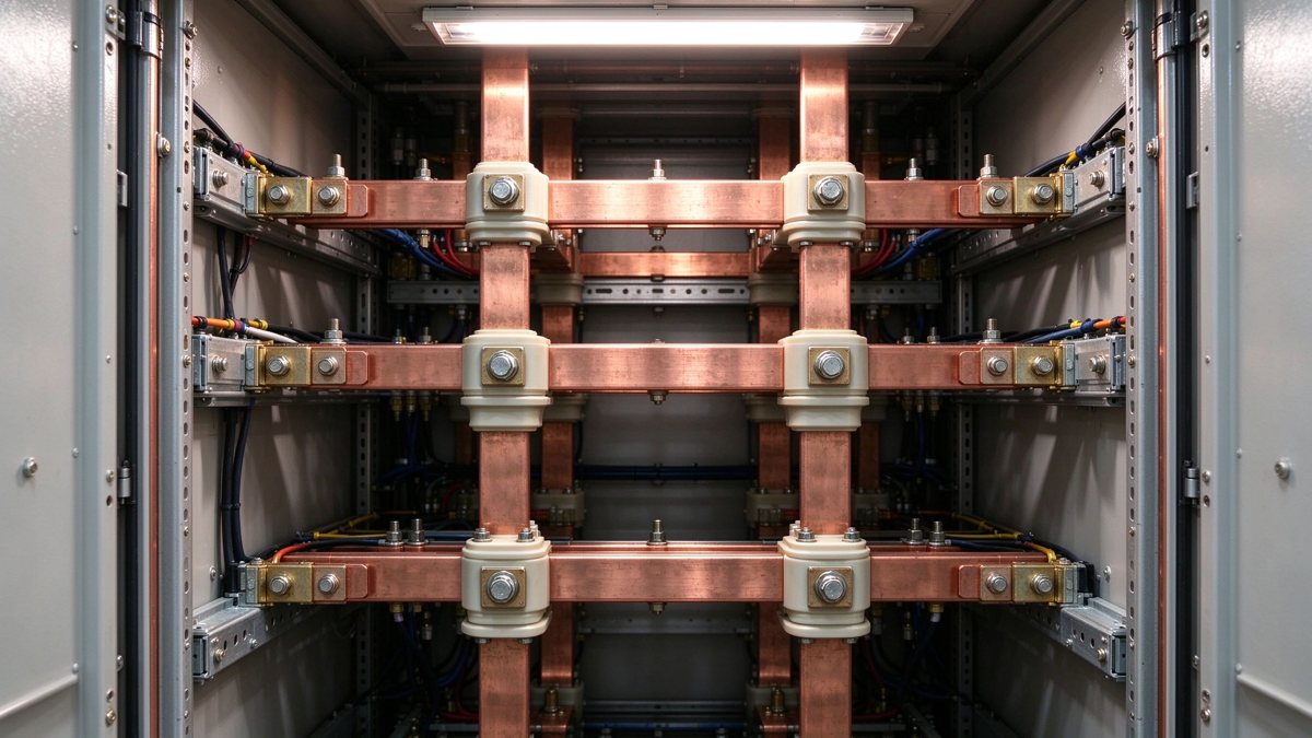
Verification practice differs between a type test and a routine check. The type test establishes the temperature-rise curve for the design in a test enclosure; the routine check only confirms that the production unit behaves like the type-tested one. For SF6-free designs the gap between the two has widened, because the internal airflow is more sensitive to small build variations such as a misplaced baffle or a cable duct left open. A periodic verification on a sample from the line, not only on the first article, is the practical compromise.
Three geometry rules show up in almost every air-insulated retrofit. First, rectangular bars are oriented with the broad face vertical where convection matters, because the boundary layer is thinner on a vertical surface. Second, bends are spaced away from barriers by at least the clearance distance plus a manufacturing tolerance, since a bend concentrates field. Third, phase order is arranged so that the highest-field pair is the one with the largest gap, which usually means interleaving rather than parallel runs.
These rules conflict with compactness, and the resolution is usually a laminated bar with an internal shield layer or a solid-insulated bar with a conductive coating at the ends. Both raise cost. The power distribution section covers how the arrangement interacts with short-circuit forces, which grow as spacing grows.
Electrodynamic force between parallel bars scales with current squared and inversely with spacing. Widening the gap to satisfy air clearance reduces the force on a single pair, which sounds helpful, but the larger enclosure often means longer unsupported spans and heavier bars, and the bending moment at a support can rise even as the force falls.
The design check therefore has to be done on the support arrangement, not on the bar alone. Peak force at 25 kA rms asymmetrical can exceed 2 kN per metre on a 40 mm bar pair at 100 mm spacing; a support at 400 mm spacing sees a moment that a 3 mm laminate will not take without a stiffener. The standards library lists the IEC 61439-1 short-circuit clauses that define the test.
The support spacing is where the calculation usually fails. A bar can carry the current and pass the temperature rise, then bend permanently at a support because the moment arm was taken from the enclosure drawing rather than from the assembled unit. Peak force at 25 kA asymmetrical on a 40 x 10 mm bar pair at 100 mm spacing is on the order of 2 kN per metre, and a 400 mm span converts that into a bending stress that a thin laminate cannot take without a stiffener or a closer support.
Air-insulated switchgear in a distribution substation is exposed to dust, humidity and occasional condensation. Pollution degree 3 is common for outdoor or semi-outdoor installations, and it changes creepage requirements by 25–40% compared with degree 2. SF6-free designs cannot hide behind a sealed gas envelope, so the busbar's insulated sections carry the burden.
Practical measures: hydrophobic coating on the epoxy or laminate surface, creepage-increasing ribs at the ends, and a housing that keeps water off the horizontal surfaces. All of them add process steps, and all of them have to survive the factory's dielectric test without partial discharge above the limit. Our connection design note includes the creepage table for the common pollution degrees.
Pollution degree is usually assigned to the installation, not to the component, but the busbar sees the consequence. An indoor substation in a coastal city can be degree 3 because of salt deposition, even though the room looks clean. The practical response is a hydrophobic coating plus a creepage profile with ribs, and a design review that assumes condensation will occur at least once a year on the coldest surface in the cubicle.
The test menu shifts. In SF6 units, gas tightness and gas quality were routine; in air and g3 units the equivalents are cleanliness, humidity and partial discharge. A practical routine for a 24 kV SF6-free unit: power-frequency withstand at the specified test voltage for one minute, PD measurement at 1.2× operating voltage with a limit in the single-digit pC range for the busbar section, and a temperature-rise run at rated current until stable.
The PD test is the one that most often fails first, because air insulation has no self-healing margin and a 0.1 mm void in a cast barrier will show up. Suppliers who treat PD as a type test only will ship units that pass withstand and fail in service after a year of thermal cycling. Write the routine PD test into the purchase specification.
How the same insulation duty behaves at 800 V DC in a vehicle-charging enclosure is a separate case, covered in the swap station busbar analysis. And once the unit is in service, the field check that catches a joint drifting is thermal, not electrical: see the infrared survey criteria for the delta-T limits that apply inside a sealed cubicle.
The temperature-rise run deserves a note on instrumentation. Thermocouples on the bar surface measure the surface, not the conductor, and a bar with a thick insulation layer can read 10 K cooler than the copper beneath it. Embedding a sensor in the terminal, or using resistance measurement to derive the average conductor temperature, gives a number that can be compared with the limits in the standard. Surface readings are useful for finding the hot spot; they are not the pass criterion.
Three drawing fields change when a platform moves from SF6 to air or g3. The insulation coordinate table gains a pollution degree and a humidity class. The temperature-rise note gains the internal ambient of the new enclosure, which is often 10 K higher than the old tank. The test section gains a routine PD requirement and a cleanliness acceptance criterion.
Suppliers who have only built SF6-era bars will quote against the old fields and miss all three. The sample-to-series process is a useful way to force the conversation: the first article is tested against the new fields before tooling is committed, and the delta is visible early rather than at series ramp.
One more drawing field changes: the gas or air volume and the pressure rating, which determine the mechanical design of the enclosure and its shipping class. A dry-air GIS at 1.5 bar has a pressure-vessel argument that an air cubicle does not, and that argument reaches back into the busbar supports and the sealing of the barrier feedthroughs. Suppliers who have only built open-air bars will miss the sealing requirement entirely.
Air-insulated cubicle: lowest gas cost, largest footprint, easiest service, best fit for 12–24 kV distribution in buildings and light industry. Dry-air GIS: compact, needs pressure monitoring and particle control, fit for constrained urban substations. g3 GIS: closest to legacy behaviour, lowest re-design effort, but gas handling and end-of-life rules still apply. Solid-insulated: smallest clearance, highest dielectric process control, fit for sealed products where the bar is never serviced.
Each route changes a different cost line: floor space, gas handling, or process control. The busbar cost difference between them is smaller than the enclosure and test cost difference, which is why the decision is usually made at platform level and inherited by the component.
The 2026 deadline moved a large installed base of 12 kV and 24 kV products into redesign at once. For busbar makers the work is unglamorous: more creepage, more shielding, tighter PD, better surface finish, documented cleanliness. It is also sticky work, because a qualified SF6-free bar is not interchangeable with a legacy one and the qualification data has a shelf life.
Suppliers who can supply the PD data, the temperature-rise run and the cleanliness records will keep the business after the first tender. Those who quote on copper weight alone will win the first order and lose the second. For a review of a specific 24 kV arrangement, the engineering contact route is faster than a drawing exchange.
Regulatory pressure rarely stops at one class. The 24-52 kV date in 2030 is already driving redesign work at the upper end of medium voltage, and high-voltage equipment is on a longer but similar path. Suppliers who qualify their air and g3 busbar processes now will be asked to repeat the exercise for a larger enclosure in three years, and the process knowledge, from cleanliness to partial discharge to surface finish, transfers even when the geometry does not.
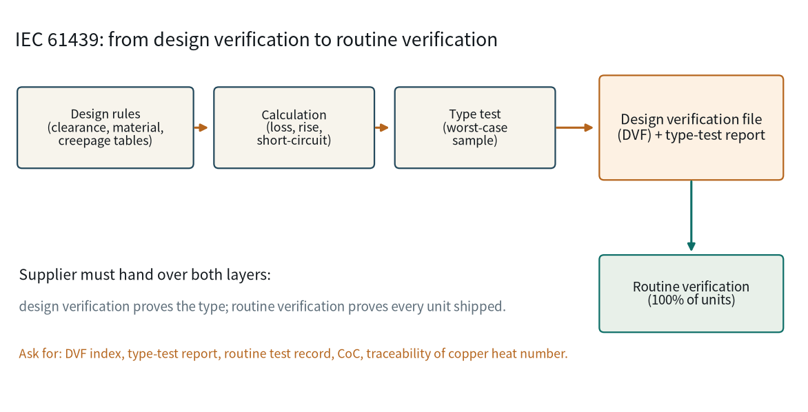
IEC 61439 governs the assembly, not the copper bar. That is exactly why busbar suppliers a
Read article
A hipot test proves the insulation did not break down in the second it was stressed. It do
Read article
Wei Chen is a dielectric and insulation specialist at SHANYUAN, with 12 years in insulation systems for laminated busbars. His work covers PET, Nomex and epoxy powder insulation, creepage and clearance design, and partial-discharge-oriented insulation coordination. He holds a Master's degree in
Send the current profile, voltage class and terminal types — our engineers reply within one business day.
