Choosing the right busbar connector is a procurement decision, not just an engineering one: it sets your first cost, your service intervals and your hot-swap capability. This guide gives buyers and engineers a decision framework — current, access, vibration and total cost — for clip, bolted and blind-mate connections.
Every busbar ends at a connection, and the connection type you choose fixes three things at once: the price you pay per joint, how often a technician must reach that joint, and whether the module behind it can be swapped while the bar stays live. A bolted joint is cheap to buy and expensive to service. A blind-mate frame costs more up front and removes the service visit entirely. For a purchasing manager comparing quotes, the line item price of a connector is rarely the number that decides total cost of ownership.
This guide is written as a selection framework, not an engineering deep-dive: it tells you what to ask, what to measure and how to shortlist, then points to the detailed engineering notes behind each family.
Bus bar connections fall into three families, each with a clear home territory.
Bolted stud-and-lug joints remain the default for fixed, never-serviced points. A correctly torqued M6 or M8 stud joint with tin-plated surfaces carries high current reliably and costs the least to manufacture. Its weakness is torque drift under thermal cycling and vibration, and every service visit means loosening, re-cleaning and re-torquing.
Open-side clip connectors slide onto a bar from outside, so the tap can sit anywhere along the bar, not only at a stud. Integrated lead-in chamfers allow hot- and load-pluggable operation. They are the right choice when tap position is unknown at drawing stage or when modules are serviced under load.
Blind-mate frames engage hidden during a drawer push-in — self-aligning, no visible access required. They suit rack modules, PDU drawers and inverter drawers where the connection is unreachable during insertion. Reference blind-mate frames run 175–265 A at a 30 °C rise, up to 365 A per contact at maximum rating when bus-terminated; clip-class joints reach about 400 A combined single-pole. Above that, parallel poles in one housing are the standard route rather than one oversized contact.
The shortlist reduces to three questions: how much current per joint, how often the joint is accessed, and how much vibration and thermal cycling the environment applies.
| Condition | Bolted stud | Clip connector | Blind-mate |
|---|---|---|---|
| Current up to ~400 A per pole | Yes | Yes | Yes |
| Hot-swap / service under load | No | Yes | Yes |
| Tap anywhere along the bar | No | Yes | No |
| Hidden connection in drawer | No | No | Yes |
| High vibration / thermal cycling | Torque drift risk | Finger contact OK | Finger contact OK |
| First cost per joint | Lowest | Medium | Highest |
| Service cost over life | Highest | Low | Lowest |
When the environment combines high vibration with planned module swaps — traction, marine, data-center racks — the bolted joint is usually eliminated in the first pass.
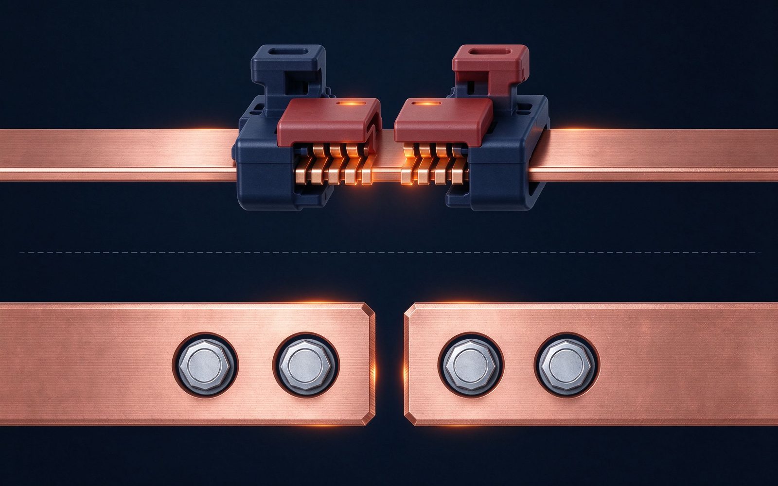
Connector current ratings are quoted at a temperature rise, and the number only means something if the rise is stated. SHANYUAN quotes connections against the same 30 °C rise used for the busbar stack: the joint is sized so that its worst-case temperature rise, measured at the contact interface, stays within the 30 °C window at rated continuous current.
Two effects decide the rise: bulk resistance of the conductor and the interface resistance at the contact points. Multi-point finger contacts spread current over several asperities, which keeps interface resistance low and stable; a single bolted land concentrates everything at one surface. This is why clip and blind-mate joints can be rated higher per pole than their physical size suggests, and why the parallel-pole rule matters above roughly 400 A: more contacts in parallel, not a bigger single contact.
Vibration converts a bolted joint into a slow maintenance problem: micro-motion between the land and lug frets the plating, oxide builds at the interface, resistance creeps up, and the joint runs hotter until someone re-torques it. In traction and off-road applications this is the classic failure sequence.
Clip and blind-mate families avoid it by design: the contact fingers are spring-loaded and independent, so each finger maintains its own normal force without relying on fastener torque. Thermal cycling from load pulses has the same effect — every cycle pushes and pulls the joint. Finger contacts accommodate the movement; a torque joint converts it into plating wear.
Where a bolted joint is unavoidable in a vibrating environment, specify hardened washers, a verified torque spec, and tin or silver plating matched to the operating temperature.
n+1 redundant distribution — the standard for data-center racks and PDU drawers — only works if a failed module can be pulled and replaced while the bar stays live. That requirement selects the connector family before anything else: the drawer side needs a blind-mate frame or clip tap with hot-swap capability, because a bolted joint cannot be opened under load.
See the full treatment in our guide to busbar power distribution architectures and n+1 redundancy; the joint families themselves are detailed in bus bar connections: clips, joins and blind-mate design.
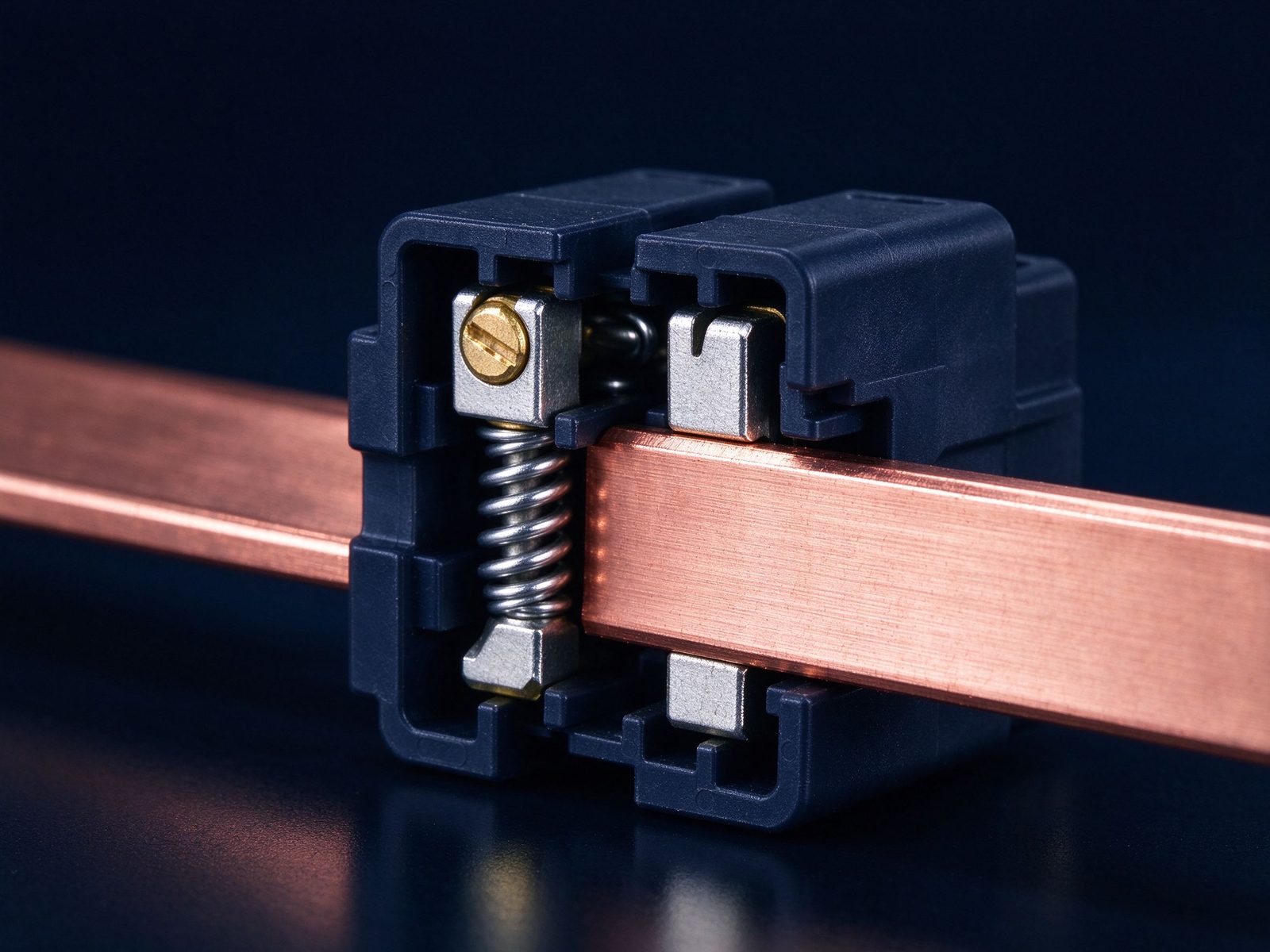
Plating is part of the connector spec, not a cosmetic option. Tin plating is the economical default for copper conductors and matches most operating temperatures; silver plating buys lower contact resistance and better performance where current density or ambient temperature is high. Plating thickness, base material and the absence of whisker-prone processing all matter at the contact interface.
For high-voltage stacks the connection choice interacts with insulation quality. A poorly finished terminal area invites field concentration at the joint; our insulation acceptance uses the IEC 60270 10 pC partial discharge criterion, detailed in the guide to partial discharge in laminated busbars.
To get a meaningful quote, give your connector requirement in six lines: current per pole and rise target; voltage class; access pattern (fixed, serviced, hot-swap); vibration and shock envelope; ambient and enclosure temperature; and the mating interface you already own (stud size, lug pattern or proprietary frame).
SHANYUAN co-designs the bar and the connection together: we size the conductor, select the dielectric by voltage class, and validate the joint against your current profile and vibration spec before tooling. Start with the laminated busbar product range, the power-electronics busbar family, or send your drawing through the contact page — our engineers respond within one business day.
Q: What is the difference between a busbar connector and a bus bar joint? A: In practice the terms overlap. A joint is the electrical and mechanical interface where two bars meet; a connector is the product that makes the joint — a bolted lug, a clip, or a blind-mate frame. Selection is about the joint's service conditions, not the name.
Q: How much current can a clip connector carry? A: Clip-class joints reach about 400 A combined single-pole at a 30 °C rise; above that, parallel poles in one housing are the standard route.
Q: Can I hot-swap a bolted bus bar connection? A: No. Opening a bolted joint under load creates an arc and a safety hazard. Hot-swap requires clip or blind-mate contacts with rated make-and-break capability.
Send the current profile, voltage class and installation conditions — we will size the busbar and document the calculation with your quotation.
Send the current profile, voltage class and installation conditions — we will size the busbar and document the calculation.
