A drawing release is the last gate between concept and manufacturing. This checklist turns the pre-release review into named owners, stated criteria and closed records.
A drawing release is the last gate between concept and manufacturing. This checklist turns the pre-release review into named owners, stated criteria and closed records.
A drawing release is the point where a design stops being a concept and becomes a manufacturing instruction. Up to that point, questions can be answered on a call, on a sketch, or in an email. After release, every dimension, every layer order and every marking on the drawing carries a cost if it is wrong: the blank may need re-cutting, the stack may need re-layering, or a batch may have to be held before it ships.
The release checklist in this guide is the gate between those two states. It does not replace the engineering review that happens at quotation. It sits after that review, after the customer drawing has been interpreted into a manufacturable busbar definition, and before tooling, first article or series order starts. The reader's action is simple: go through each item, mark it pass or open, and do not sign while an open item remains.
Many busbar problems that look like shop-floor defects trace back to a drawing that was released too early: a bend that the blank cannot reach, a stud that the wrench cannot fit around, a layer order that the insulation supplier cannot bond. Each of those is visible on the drawing before production starts, if someone looks for it. The busbar design guide covers the earlier design choices; this checklist covers the last gate before the drawing leaves engineering.
A checklist only works when each row has a named owner. Three roles usually sign the release, each with a defined part to confirm:
On each row, the owner answers three questions: what are we looking at, what does a pass look like, and what do we do if it fails. A row marked "looks fine" without a stated criterion is not a pass. The quality system behind the release is described on the quality process page; this guide focuses on the drawing-level evidence that feeds that system.
This one is easiest to skip when a program is behind schedule. The pressure is to release now and sort out details later. That pressure is exactly what the gate exists to resist: a late release costs days, a wrong release costs weeks and can stop the customer's line.
Start from the flat blank, not the finished shape. A laminated or bent busbar is cut from a copper sheet or strip, then formed; the released drawing must show both the developed blank and the formed geometry, so the shop can check that the blank actually unfolds to the part on the print.
Check the bend radius against the material temper and thickness. A radius that is too tight for the chosen temper cracks the outer fibre during forming; a radius that is larger than the design assumed changes the centerline length and pushes terminal positions off the assembly. The exact radius and its limits are given by the drawing and project specification, not by a generic rule applied to every grade. Cross-check the copper grade, temper and bend severity together; a grade that forms well in one temper may not in another. The bend radius design guide goes deeper into forming limits and springback.
What happens if this row fails: the blank is cut to the wrong development length, bends crack or neck during forming, and the formed part lands outside the interface position. The shop can rework a few pieces by straightening and re-forming, but cracked material cannot be repaired; those pieces are scrapped. In a batch, the error repeats on every blank cut from the released development, which turns a drawing-level miss into a batch-level loss.
Also check that holes, slots and terminal features are placed so the forming operation does not pull them out of position. Features too close to a bend distort when the material moves; features that sit in the bend zone itself may be unusable after forming.
For a laminated or multi-layer bar, the released drawing must state the stack order unambiguously: which copper layer sits on top, which dielectric separates which pair of conductors, and where the insulation wraps, stops or exposes a contact zone. A stack order that can be read two ways will be built the wrong way on the first run.
Check the dielectric material, thickness range and application against the service conditions: voltage class, operating temperature, humidity and any chemical exposure in the enclosure. The material choice is not a cosmetic detail; it decides bonding, edge margin and how the insulation survives thermal cycling. The dielectric selection guide covers material families and their trade-offs. Confirm that exposed edges, cut faces and weld zones are protected the way the drawing describes, and that the insulation overhang matches the lamination process the factory will run.
What happens if this row fails: layers are stacked in the wrong order, conductive faces touch where insulation was assumed, or the dielectric delaminates after assembly. The first two usually show up at first article as an insulation failure or a short between layers. Delamination can surface later, after parts have reached the customer, which is a more expensive return than a caught first-article rejection.
Mark the stack on the drawing itself, layer by layer, rather than leaving it in a meeting note. Notes do not travel with the job; the released drawing does.
Terminals, studs, threaded inserts and mounting holes are the points where the bar meets the rest of the system. On the released drawing, check each one against three things: position relative to the mating part, the hardware it will carry, and the space the installer needs to tighten and check it.
Position means the terminal or stud lands where the mating connector, bolted joint or module expects it, with orientation clear from the view. Hardware means the hole or stud matches the fastener class and the load path the design assumed. Tool access is the part that drawing reviews miss most often: a wrench, socket or torque tool has to fit around the terminal, reach the joint face, and turn without hitting an adjacent layer, the enclosure wall or another bar. A terminal that looks reachable on a flat drawing can be trapped between layers in the assembled stack.
What happens if this row fails: the installer cannot get a tool onto the joint, the fastener cannot reach clamp load, or the terminal interferes with the mating part on the production line. Interference shows up as an assembly stoppage: parts come in, fit does not happen, and the line waits while engineering sorts out whether the bar or the interface moved. A joint that cannot be checked with the specified tool also leaves torque unverifiable, which is a quality hold even if the fastener turns.
Check access from the actual installation side, not the most comfortable drawing side. If the joint is reached from below, or through a narrow opening, simulate that direction on the released geometry before sign-off.
No feature lives on its own. A terminal position, a stud height and a mounting hole each carry their own tolerance, and those tolerances stack through the assembly: bar to bar, bar to module, module to enclosure. The release review follows the chain rather than judging each feature in isolation.
Check which features matter for fit and function, and trace their variation through the mating parts. Critical interfaces get tighter control; non-critical features do not need the same treatment. All tolerance values and fit classes are given by the drawing and project specification; this guide does not assign generic numbers. The fabrication tolerances guide explains how tolerances are allocated across blanking, forming and assembly operations. Look for places where several loose features meet at one joint: that is where the chain accumulates, and where first article surprises come from.
What happens if this row fails: parts fit individually but do not assemble together. The bar goes in crooked, the stud does not line up with the mating hole, or a clamp load cannot be reached because the faces do not meet. Some mismatches can be compensated on the bench during a prototype build; on series production, the compensation does not scale, and assemblies start failing the fit check at the customer's line.
Verify that the released drawing shows datum references consistent with the inspection plan. A part measured from the wrong datum passes the shop check and still misses the assembly interface.
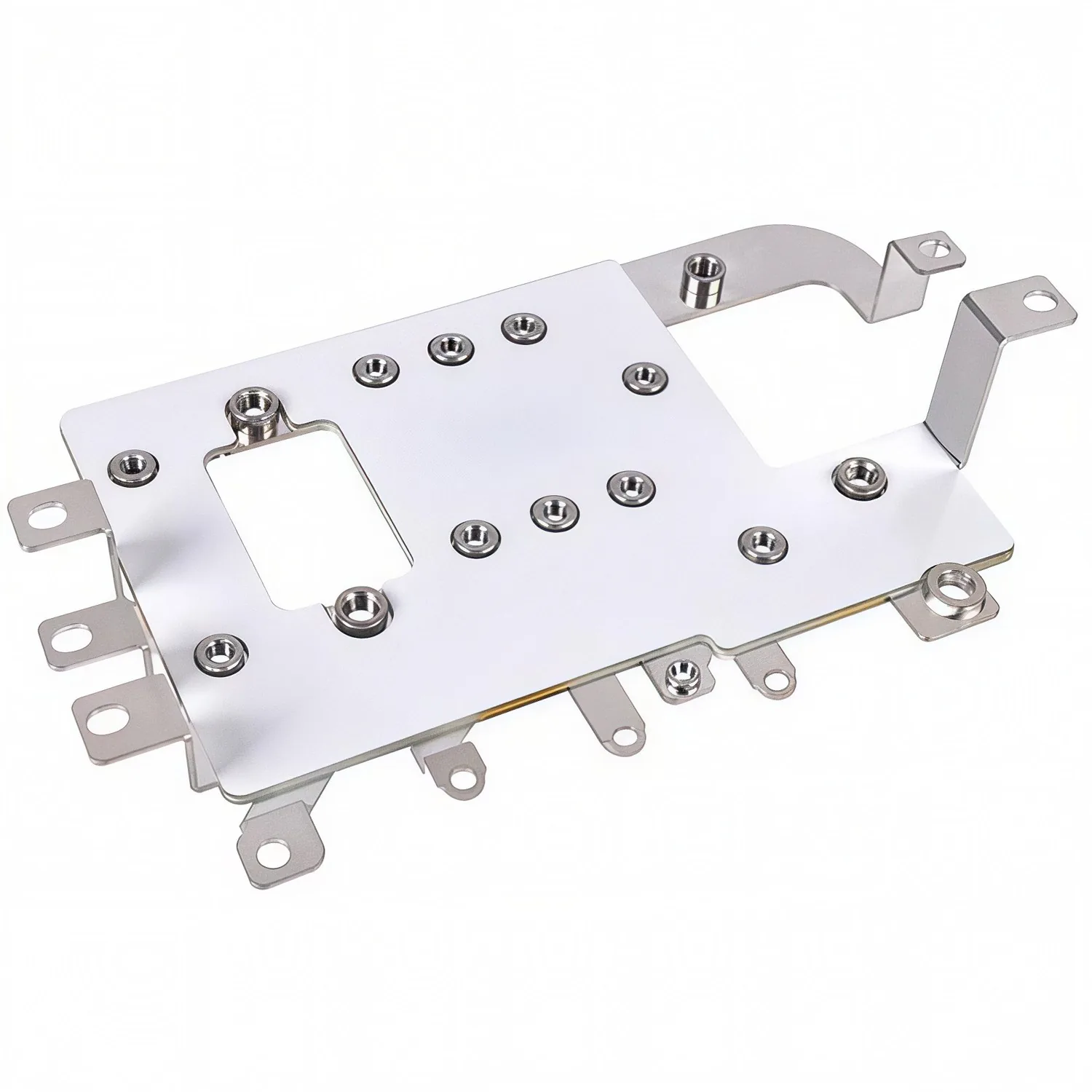
Plating defines both corrosion protection and joint performance. On the released drawing, the plating spec states the finish, the thickness range, where plating applies and where it must be masked off: weld zones, bond faces and insulation contact areas are common masks.
Check that the mask lines on the drawing match the process: plating cannot be stripped from a zone that was dipped, and a plated weld face changes the weld. The electroplating process guide walks through finish families and masking practice. Marking comes next: the part identity, revision and any traceability mark must sit on a face that stays visible after assembly, away from contact zones, bend radii and insulation overlap. A mark buried under a layer or hidden against the enclosure defeats traceability.
What happens if this row fails: a weld zone arrives plated and the weld is rejected; a bond face is plated where insulation needs to grip; or the mark wears off or is unreadable on the finished part. Plating errors on a batch mean the whole batch goes back for stripping and re-plating, or gets scrapped if the substrate is affected. A missing or unreadable mark means the parts cannot be traced to their revision, which holds shipment until the records reconcile.
Electrical separation is checked on the released drawing against the project's voltage class and environment. The review confirms conductor spacing, insulation coverage, edge protection and the paths current could track across a surface or through a gap.
Check creepage and clearance along the actual surface route: across edges, around exposed terminals, over insulation ends and through any slot or cutout. Surface paths are longer than a straight-line drawing distance, and pollution, moisture or altitude in the service environment can tighten the requirement. The final values and test voltages are set by the type-test report and project specification, not by a generic table. The creepage and clearance design guide describes how paths are read on a busbar drawing. Confirm the withstand test listed in the inspection plan matches the insulation construction on the released part.
What happens if this row fails: the part passes a visual check but fails the withstand or creepage test, or worse, survives internal validation and tracks in service. A test failure at first article holds the lot; a separation defect that reaches the field is a safety and warranty issue, not just a rework item. Where spacing was underestimated in the release, there is often no bench fix: the insulation or layer layout has to change, which means a drawing revision and a new first-article check.
A released drawing defines how the part leaves the factory as well as how it is made. Packaging and oxidation protection belong in the release review because they protect the surface the plating and machining produced.
Check whether the finish needs anti-tarnish protection, separator sheets or moisture control for the planned transit and storage conditions; whether bent or laminated faces are supported so they do not rub against each other in the box; and whether terminals and exposed contact zones are covered against dents and fingerprints. Parts that will sit in storage before assembly should have a documented protection method, not a generic bag.
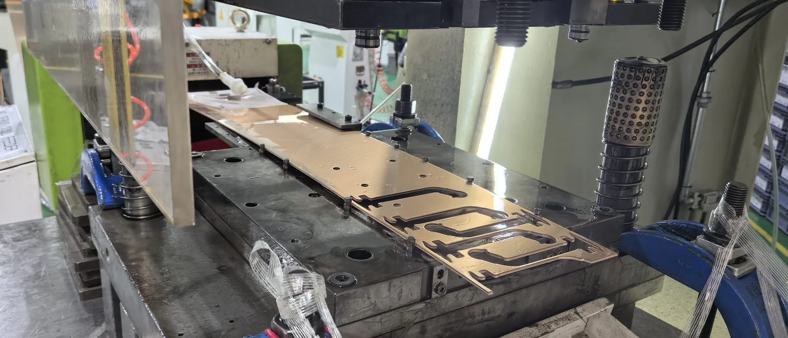
Credit: SHANYUAN factory library.
What happens if this row fails: copper tarnishes or oxidizes in transit, plated faces tarnish, or parts scuff against one another and arrive with damaged contact surfaces. Tarnish can be cleaned on a few prototype pieces; on a series batch it means re-processing before assembly, and deep oxidation on contact faces can make the parts unusable. A dent to a terminal or a bent layer from poor packing is a mechanical defect the customer rejects on arrival.
Every released drawing carries a revision state, and that state has to agree across the drawing file, the inspection plan, the bill of materials and any customer correspondence. The release review checks the record, not just the paper.
Confirm the revision letter or number matches the latest change, that prior revisions are marked superseded, and that each change is described well enough to tell what moved: dimension, layer order, plating, marking or material. Open change requests should sit in a visible open-issues list, not be silently folded into the release. Where the customer approved a deviation, that approval is part of the record, with its scope and expiry noted.
What happens if this row fails: the shop builds from an old revision while quality inspects against a new one, or vice versa. Parts that match one document fail the other. A traced-back batch then has to be sorted by revision, which holds shipment; if the wrong revision has already shipped, recall and field reconciliation follow. This one is easy to underestimate because the physical part looks the same between revisions — only the record shows the difference.
The release should define the anchors that keep the first accepted part and the series parts the same. First article is not a one-off approval; it is the reference against which later runs are compared.
Check that the drawing identifies the dimensions, positions, plating, insulation and marking that first article will be inspected against, and that those anchors stay the same in series. The first accepted sample should be recorded with its measurements and any approved deviation, so a later run can be compared to a documented baseline rather than to a memory. If the program expects a second source or a changed production route later, the release should note which characteristics must be re-qualified and which carry over; the second-source requalification guide lists what has to be re-verified when the manufacturing route changes.
What happens if this row fails: first article passes, series drifts, and nobody has a documented baseline to notice the drift against. Small shifts in blank, layer order or plating accumulate until fit or insulation fails in production. A later requalification then has to reconstruct what the original part was, which costs more than recording the baseline at release.
Keep the first-article record attached to the released drawing. It is part of the release package, not a separate file someone can lose.
Run through the following items before anyone signs the release. Each row should carry a pass result, an open status with an owner, or a hold note. Do not move an open row to pass without evidence.
The table below pairs each release area with its release criterion and the consequence that follows when the row is signed off without a pass. The consequences range from isolated rework to batch scrap and a customer line stop; the further downstream the miss surfaces, the more it costs.
| Check item | Release criterion | What a miss costs |
|---|---|---|
| Unfolded blank and bend radius | Development length and radius match grade, temper and thickness; features clear of bend zones. | Cracked or necked bends, wrong terminal positions; cracked parts scrapped, repeat loss across the batch. |
| Stack order and dielectric | Layer order readable one way only; material and thickness match service conditions. | Wrong layer order, short or insulation failure at first article; delamination risk later in the field. |
| Terminal and stud access | Position, orientation and hardware match the interface; tool reaches the joint from the installation side. | Assembly interference, unreachable joint, unverifiable torque; line stoppage while fit is sorted out. |
| Tolerance chain and fit | Critical interfaces traced through mating parts; datums match the inspection plan. | Parts fit alone but do not assemble; series fit failures at the customer's line. |
| Plating and masks | Finish, range and mask zones stated; weld and bond faces protected as drawn. | Rejected welds, poor bond grip, batch stripping and re-plating or scrap. |
| Marking location | Identity and revision visible after assembly, away from contact and bend areas. | Untraceable parts, shipment hold until records reconcile. |
| Insulation, creepage, clearance | Surface routes checked against voltage class and environment; test plan matches construction. | Withstand or tracking failure; safety and warranty exposure, layout revision and new first article. |
| Packaging and oxidation | Protection method defined for transit and storage; faces supported and separated. | Tarnish, scuffed contact faces, dented terminals; rejected arrivals or batch re-processing. |
| Revision and change record | Drawing, plan, BOM and deviations share one revision state; changes described. | Wrong-revision build and inspection, shipment hold, possible recall and reconciliation. |
| First-article baseline | Inspection anchors documented and retained for series comparison. | Undetected series drift; costly reconstruction when fit or insulation fails later. |
Signing the release is a commitment, not a formality. When an open item cannot be closed with evidence, the correct action is to hold release and list the open issue with its owner and due date. A provisional sign-off, a verbal agreement or a note to "fix it in production" does not close the row.
Common hold triggers: a mating interface still awaiting the customer's final drawing; plating or insulation material not yet confirmed against the environment; a tool-access question that needs a mock-up; a deviation without documented approval; or an inspection plan that does not yet match the drawing. Each of these can be resolved, but resolution belongs before the parts are cut, not after.
If a released part later shows that a release item was missed, treat it as a release-process lesson, not just a shop defect: check whether the same gap exists on other programs, and update the checklist. Defects found after release often require rework or rejection of the affected batch; the rework and repair acceptance guide defines which defects can be reworked, which must be scrapped, and what re-inspection a repaired part needs.
Once the checklist is closed and the drawing is released, the next step is the first-article build against the recorded anchors. Samples can be ordered against the released definition on the custom copper busbar product page; sample pricing starts from US$52 for large laminated assemblies on the product page, and series pricing is quoted against the released drawing. Order quantities and lead time are agreed per project.
If the program is still choosing a construction rather than releasing one, the busbar selection decision matrix maps current, layer count, environment and batch to a recommended layout before this release gate applies. For questions on a drawing in progress, send the geometry and interface requirements through the contact page; engineering reviews the blank, stack and access points before the quote is finalized.
A joint that is tight is not the same as a joint that is correct. Torque windows, pull lim
Read article
A second source is supposed to reduce risk, and it usually adds some instead: the drawing
Read article
Thomas O'Brien is a manufacturing process engineer with 14 years in stamping, lamination and terminal machining for laminated busbars. He manages production lines for precision-cut profiles, insulation layering and CNC terminal processing, and focuses on dimensional control and repeatability at
Send the current profile, voltage class and terminal types — our engineers reply within one business day.
