A busbar that fits the cabinet perfectly on the drawing often fails on the press brake: copper work-hardens, springback moves the angle, and a tight inner radius cracks the surface and the insulation. The rules in this guide — radius-to-thickness ratios, grain direction, plating order and tolerance strategy — turn bending from a manufacturing surprise into a designed feature.
A busbar that fits the cabinet perfectly on the drawing often fails on the press brake: copper work-hardens, springback moves the angle, and a tight inner radius cracks the surface and the insulation. The rules in this guide — radius-to-thickness ratios, grain direction, plating order and tolerance strategy — turn bending from a manufacturing surprise into a designed feature.
Bending stretches the outer surface and compresses the inner surface of the copper. Below a critical inner radius, the outer surface strain exceeds the material's ductility and micro-cracks appear.
For copper, that critical radius is expressed as a multiple of the material thickness: tighter than about 1× thickness, cracking risk climbs quickly.
Soft (annealed) C11000 copper bends easily but work-hardens — the bend zone becomes harder and less ductile than the parent material, which matters for any subsequent bending or forming in the same area.
Order the operations so that critical bends happen before hardening, or specify half-hard temper where the final strength needs to be higher than soft copper provides.
As a practical rule for C11000: minimum inner radius ≈ 1× material thickness for soft copper, 1.5-2× for half-hard, and 2-3× where plating or insulation must survive the bend. Thick bars (10 mm and above) generally need larger ratios because surface strain concentrates.
When in doubt, specify the larger radius: the cost is a few millimetres of envelope, the benefit is no cracks and no scrap.
There is also a practical thickness effect: thin bars bend with generous radii relative to their thickness, while thick bars approach the ductility limit quickly. A 3 mm bar can usually take a 3-4 mm inner radius; a 12 mm bar needs 15-25 mm, and the bend zone will show some ovality even at the correct radius.
Copper is rolled, and rolling gives the material a grain direction. Bending parallel to the grain (the bend line running along the rolling direction) is more crack-prone than bending across it.
On stamped blanks, align the bend line across the rolling direction where possible. The drawing should state the bend direction if the blank is grain-oriented.
A sharp (near-zero radius) bend concentrates all strain at one line and cracks copper and plating. Radius bends spread the strain over the arc and are the only sensible choice for plated or insulated parts.
If a sharp bend is unavoidable, expect reduced fatigue life and additional inspection — and flag it in the DFM review.
For grain-oriented blanks, the drawing should mark the rolling direction with an arrow and the bend lines relative to it. If the part has two bends in different orientations, the blank layout decides which direction each bend sees — a conversation worth having with the fabricator before the die is cut.
Plating is applied to the flat blank or after bending, and the order changes the risk. Tin plated before bending can crack or flake at the outer surface of the bend.
Best practice for visible terminations: bend first, then plate, or plate and re-flow. Where pre-plated stock is required, use the larger bend radius and confirm adhesion with a bend test on the first article.
For laminated (insulated) busbars, bending is done on the bare copper before lamination, or the lamination is designed to accommodate the bend. PET and Nomex do not stretch like copper; bending a laminated stack cracks or delaminates the dielectric.
If the final part must be bent and insulated, two options exist: bend the bare copper with the radius rules above and then apply conformal edge-sealed insulation, or design the lamination as flat segments joined by the bend geometry.
Copper springs back after bending: the part opens up from the tool angle. The amount depends on temper, thickness and radius — typically 1-3° for soft copper, more for harder tempers.
Production compensates with over-bending (tool angle slightly tighter than target). The drawing should specify the finished angle and tolerance, not the tool angle; the shop handles compensation.
Bent dimensions accumulate error from the bend itself: angular tolerance, bend-line position and springback. ISO 2768-mk gives a starting point; tighter angular tolerances (±0.5° or better) are achievable but cost more in setup and inspection.
Only tighten what the assembly actually needs. A tolerance on an unconstrained flange adds cost and inspection time without protecting any fit.
Springback compensation is part of the tooling design: the punch angle is set tighter than the target, and the die radius is held at the finished inner radius. Because copper's springback varies with batch hardness, a fabricator with hardness measurement on incoming copper holds angle tolerance more reliably than one who compensates once and hopes.
A bend does not change the cross-section, so the DC ampacity of a bent busbar is the same as the straight bar — but the local strain at a tight bend raises resistance slightly and can create a hot spot in high-current service.
For high-duty links, use radius bends and keep the current density at the bend below the straight-bar limit.
An L-shaped busbar (90° bend) for a 5 mm thick bar needs an inner radius of at least 5-10 mm. A U-shaped busbar (two bends) needs consistent radii and a bend allowance that keeps the two legs parallel within the angular tolerance.
In both cases the neutral axis (roughly at mid-thickness for small radii) defines the developed length; ask the supplier to confirm the blank length from the neutral axis, not the outer dimension.
The developed length deserves the same care as the radius. For small radii the neutral axis sits close to mid-thickness; for larger radii it shifts. A blank that is cut 5 mm short at the bend line produces a flange that misses its position by more than most drawings allow, and the fix is to calculate the blank from the neutral axis, not from the outer envelope.
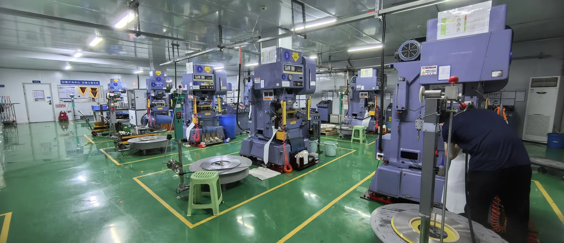
Small series and large bars are typically formed on CNC press brakes with programmable backstops; high-volume small parts are stamped with progressive dies that bend in-sequence.
SHANYUAN performs CNC bending and stamping in-house, with first-article inspection of bend radius, angle and plating integrity on every setup.
Before sending the drawing: (1) inner radius ≥ 1× thickness for soft copper, more for plated or insulated; (2) bend line across grain where possible; (3) plating order defined (bend-then-plate preferred); (4) angular tolerance realistic; (5) developed length from neutral axis; (6) clearance for tooling (minimum flange length); (7) bent section current density checked.
Items 1 and 3 prevent the two most common field failures: cracked copper and lifted plating.
Bend radius is a design parameter, not a shop-floor afterthought. The rules are simple — radius at least 1× thickness, bend across the grain, plate after bending, compensate springback — and they turn bending into the cheapest routing tool in the cabinet.
SHANYUAN reviews bend geometry in every DFM pass and quotes from drawings within one working day, including bent and laminated combinations.
In short: the bend is the cheapest routing tool and the most common source of scrap. Apply the radius rule, bend across the grain, plate after bending, compensate springback, and let the DFM review be the gate — bent busbars then go from manufacturing risk to competitive advantage.
A bend is a one-piece connection: it needs no fastener, no weld bead and no contact interface, so it adds no contact resistance and no joint to maintain. That makes bent transitions attractive for high-current paths inside cabinets.
The trade-off is geometry: a bent part consumes envelope and must respect the radius rules above, while a bolted or welded joint can route at right angles in a smaller footprint.
Design guidance: use bends for routing and for one-piece current paths; use bolted joints where disassembly, plating flexibility or flat stacking matter more than the extra contact resistance.
Bent busbars fail in characteristic ways, and each has a visual signature: cracked copper at the outer surface of a tight bend (too-small radius or wrong grain direction), lifted or flaking plating (bending after plating), dielectric delamination at the bend (bending a laminated stack), and angular error from uncompensated springback.
First-article inspection should cover bend radius (profile gauge), angle (protractor or CMM), plating integrity (bend-test coupon) and, for insulated parts, a hipot check across the bend zone.
Sampling frequency depends on the process: CNC press brakes with programmable backstops hold angle well, so per-lot first-article plus periodic checks are usually sufficient.
Consider three common cabinet layouts. First, a vertical main bus that must reach a breaker at 90°: a 6 mm thick bar needs an inner radius of 6-12 mm, and the bend consumes roughly 15-25 mm of height per leg. Second, a U-shaped transfer bar between two breaker rows: both bends use the same radius, and the leg-to-leg tolerance is held by the backstop position. Third, a shallow S-bend for a low-profile DC link: two bends in opposite directions, each needing clearance from the other's tooling.
In all three cases the design sequence is the same: decide the radii first, calculate the developed length from the neutral axis, mark the grain direction, and leave the angular tolerance realistic.
A fourth case worth naming: a bent bar that doubles as a mounting bracket. Combined electrical-mechanical parts save parts count but couple the bend tolerance to the mounting hole pattern — one DFM conversation saves the whole assembly.
When in doubt, send the bend layout to the supplier for review before the die is cut; the review costs days, the rework costs weeks.
A busbar's reliability is decided in the first 2 mm of the drawing: hole position, bend an
Read article
Every hour spent on DFM before a custom busbar quote saves a week of rework. This is the c
Read article
The terminal is where a laminated busbar meets the outside world. This guide covers M6/M8
Read article
Thomas O'Brien is a manufacturing process engineer with 14 years in stamping, lamination and terminal machining for laminated busbars. He manages production lines for precision-cut profiles, insulation layering and CNC terminal processing, and focuses on dimensional control and repeatability at
Send the current profile, voltage class and terminal types — our engineers reply within one business day.