Most busbar inquiries start from a part number or a current rating, not from the conditions that should drive the construction. This guide turns those conditions into a repeatable selection matrix, if-then rules and an RFQ checklist engineers and procurement can use in the same meeting.
Most busbar inquiries start from a part number or a current rating, not from the conditions that should drive the construction. This guide turns those conditions into a repeatable selection matrix, if-then rules and an RFQ checklist engineers and procurement can use in the same meeting.
This guide answers one question: given the conditions of a project, which busbar construction and which supply route should you commit to before the inquiry goes out. It is a decision framework, not a primer on how copper carries current. If you need a geometry recommendation in a design review, a checklist to put inside an RFQ, or a way to catch an over-specified or under-specified part early, the matrix and rules below are built to be used in a meeting room.
The framework speaks to two readers at once. The engineer chooses the conductor family, layer count, insulation and joint style. The procurement specialist turns those conditions into a complete inquiry so the supplier can quote a buildable part rather than a placeholder estimate. The seven dimensions, the decision matrix, the if-then rules and the RFQ checklist are written to be copied straight into a project file.
Scope boundary, stated plainly. This guide covers construction type and supply route selection only. It does not tell you how to screen a manufacturer: factory audit, quality evidence, capacity and commercial fit are handled in the busbar manufacturer due-diligence guide. It does not explain how to normalise competing quotes: copper basis, tooling, plating, test scope and delivery terms are covered in the quote comparison framework. It does not argue in-house manufacture versus outsourcing; that break-even question is the make-vs-buy framework. Layer-count trade-offs within a laminated stack are detailed in the layer-count selection guide, and order-level total cost of ownership is a separate TCO framework.
One more boundary before the matrix: every current, voltage, creepage, temperature and vibration limit below is an engineering category, not a certified threshold. The final numbers come from your project specification and the type-test report for the chosen assembly. This guide tells you which condition to ask about, not what the approved limit is for your application.
A busbar choice goes wrong most often when one condition carries the whole decision. A buyer sees a high current and asks for the heaviest laminated stack on offer, or sees a tight budget and strips plating off a part that will sit outside. The matrix below starts from seven conditions, because the right construction is where all seven line up.
Work through the seven in order. The current and voltage dimensions narrow the conductor and insulation range. The environment dimension selects surface treatment and sealing. The batch and lead-time dimensions decide whether bespoke tooling can be justified. The documentation dimension then checks that the chosen route can actually produce the evidence your audit chain requires.
Continuous current sets the cross-section and the thermal path. A bar that carries steady current heats by resistive loss; the copper area, the cross-sectional shape, the airflow around the bar and the neighbouring heat sources together decide the temperature rise. Skin effect and proximity effect push current toward conductor surfaces at high frequency, and harmonic content in an inverter or rectifier waveform raises losses above the DC equivalent. The ampacity calculation guide walks through those derating steps in detail.
Peak current matters for a different reason. Short-time fault current and switch-on peaks produce electrodynamic forces that scale with the square of the peak value, and joints must survive that duty without loosening or yielding. A part sized only for continuous heating can look thermally fine and still fail mechanically during a fault event. Record both numbers in the inquiry: the steady ampere, the peak ampere, how long the peak lasts, and how often it repeats.
Current alone does not pick a construction family. A 400 A run may be a single rigid bar in a clean cabinet, a 2-layer laminated link inside a converter, or a flexible foil section between two vibrating modules, depending on the other six dimensions. Treat current as the sizing input, not the route decision.
Voltage class decides what the insulation between conductors must do, not how much copper it holds. Clearance is the air distance between live parts; creepage follows the surface of the insulation between them. Both widen with voltage, pollution degree and altitude, and both depend on the material group of the dielectric you choose. The insulation-coordination tables in IEC 60664-1 are the reference for how these distances scale; your project specification sets the actual values.
Inside a laminated stack, adjacent planes are separated by a thin dielectric film rather than air. That changes the failure mode. Sharp copper edges, pinholes and voids in the film can concentrate the electric field and start partial discharge, which erodes insulation over thousands of operating hours. PD-sensitive installations therefore need a qualified dielectric, edge relief at cut-outs and an acceptance measurement on the finished stack. Generic film bought on price rarely clears that check on its own.
When you read the busbar design guide, note where clearance and creepage are measured along surfaces versus through air. A layout that looks acceptable on the drawing can fail once a connector, a screw head or a label sits across the creepage path. Flag those interfaces early; moving a hole or adding a slot is cheap before tooling, expensive after the stack is laminated.
Four construction families cover most busbar programs. Know what each one buys and what it costs before matching it to the conditions.
Single rigid bar — one copper or aluminum conductor, punched, bent or machined to shape, with insulated faces where required. It is the simplest and cheapest family to produce, and bolted joints are easy to inspect. It carries one current path; it does not cancel loop inductance between closely spaced conductors.
Multi-layer laminated stack — two or more copper planes interleaved with dielectric and bonded into one assembly. Interleaved positive and negative planes cancel loop inductance, and multiple zones can route DC, AC or three-phase paths in a single footprint. The layer-count selection guide covers the current-sharing and thermal trade-offs behind 2-, 4- and 6-layer builds; the low-inductance layout notes explain why plane pairing matters at the switching loop.
Flexible laminated link — a foil or thin-layer stack that stays soft in the plane, used between two interfaces that move, misalign or expand at different rates. It relaxes joint stress and absorbs tolerance stack-up. It is not a fault-duty structure by itself. The rigid-versus-flexible comparison in the flexible busbar selection guide spells out where each family belongs.
Standard module variant — an existing terminal or busbar platform modified locally for your hole pattern or length. It reuses released tooling and a qualified layup, which keeps NRE and first-article cycle time down. The trade-off is that the envelope follows the existing platform; a bespoke geometry cannot be forced into it.
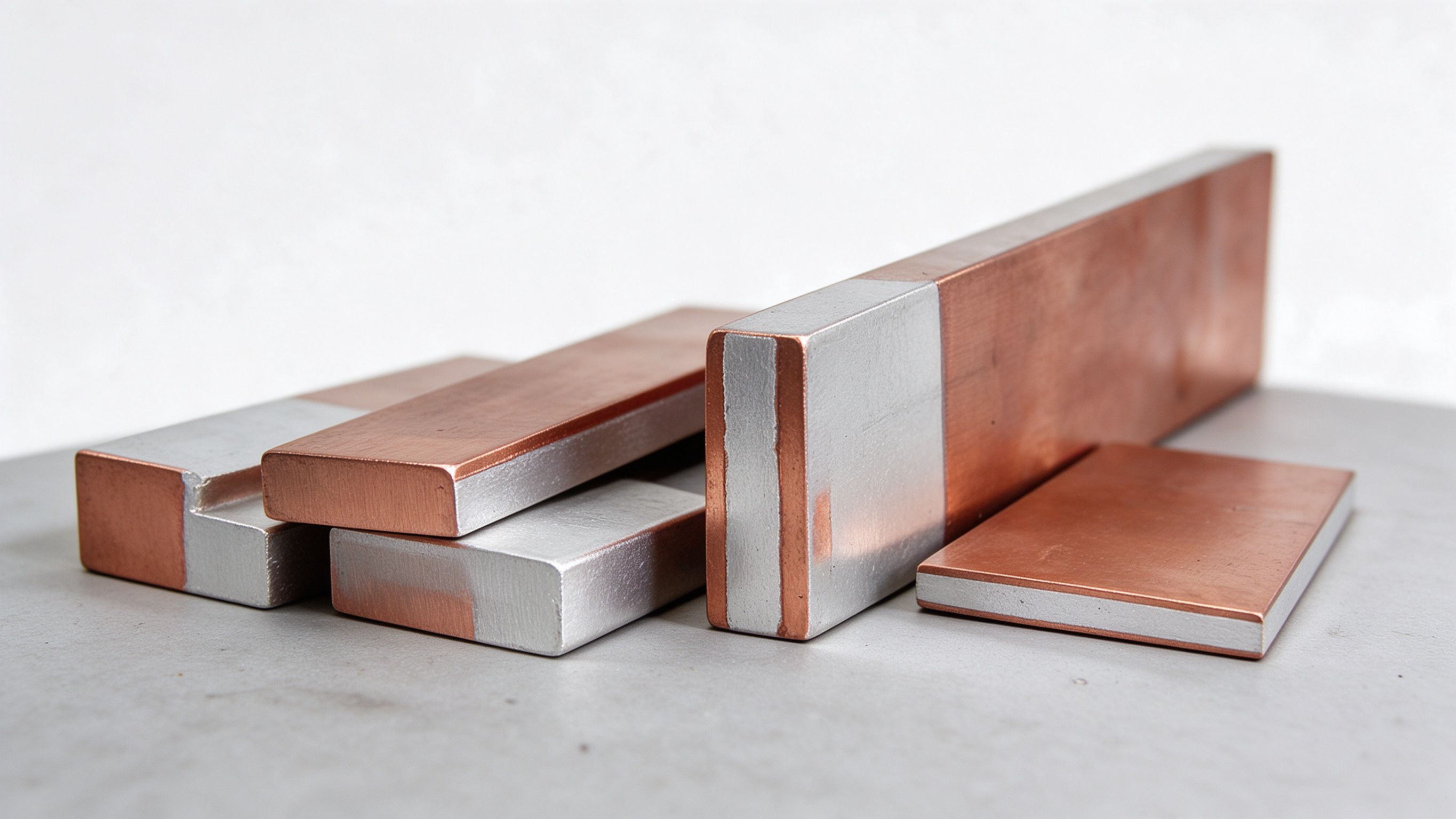
Environment decides the surface treatment, the insulation system and how the bar is supported. Indoor clean-air cabinets are the easy case: bare or lightly tinned copper faces, standard film insulation, fixed supports. Exposed or partially exposed locations add requirements that a catalogue part may not meet.
Humidity and airborne pollution drive surface degradation. Copper oxidizes when moisture and contaminants sit on an exposed face; oxide layers raise contact resistance at bolted joints, and the joint heats, which accelerates further oxidation. Plating — tin, nickel or silver per the contact requirement — protects the exposed copper, and sealed insulation keeps moisture off faces that do not need to be touched. Coastal or wash-down environments add salt spray, which is a harsher corrosion regime than plain humidity; plating thickness, edge sealing and creepage should all be reviewed against the corrosion guidance in the plating and corrosion selection guide.
Temperature drives two choices. The conductor temper and cross-section must hold the continuous heating margin, and the insulation system must be rated below its upper thermal endurance limit with cycling in mind. Dielectric film ages faster near its rated ceiling; a part that sits near the limit in a hot cabinet loses insulation life well before the copper wears out. Vibration and shock push the other way: rigid bars need support spacing that keeps resonance away from operating frequencies, and interfaces between two modules that move relative to each other usually call for a flexible section rather than a rigid bolted bridge.
Volume changes the route more than it changes the geometry. A low-current part made once for a prototype rack does not justify a stamping die or a laminated layup; the same geometry repeated every month for three years can pay for tooling many times over. Match the fabrication route to the expected release rhythm, not to the one-off sample you hold in your hand today.
At very low volume, laser-cut or machined rigid bars, and standard terminal modules with local modification, carry the part without dedicated NRE. Small parts carry a sample price from US$12–20 on the product page; production pricing is quoted per drawing, because copper basis, plating and test scope vary by design. At mid volume, punched and bent rigid parts start to make sense, and a simple 2-layer laminate becomes defensible once the inductance or consolidation benefit is real. At high steady volume, laminated tooling and repeated layups amortize against repeatability, joint consistency and the number of separate parts eliminated from the assembly.
Rhythm matters as much as total count. A program that releases 200 pieces once and then never returns behaves like low volume even if the number looks large on paper. A program that releases 300 pieces every quarter for four years behaves like high volume, and tolerances, tooling and supplier planning should be quoted that way. State the forecast horizon in the inquiry; a route chosen for a one-off run will not protect a five-year program.
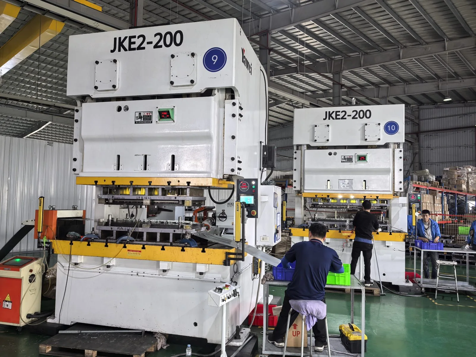
Credit: SHANYUAN factory library.
Some programs gate release on evidence, not on the part alone. An automotive, rail, utility or storage customer may ask for first-article inspection, material traceability down to the copper lot, plating thickness records, insulation material certificates, dielectric and PD test results, and a certificate of conformity per shipment. The construction choice has to leave room to produce that evidence: test coupons on the panel, marked lots, inspection access at each joint.
Match the documentation route to the audit chain your market expects. A supplier that routinely issues the dossier your customer audits can hand over certificates and test reports with the shipment; a supplier that builds good parts informally may struggle to reconstruct the record after the fact, even when the parts themselves are fine. Ask early which standards the assembly must support — the switchgear assembly standard, the insulation-coordination practice, the component or enclosure rules for your sector — so the chosen construction can be tested against them.
Do not treat documentation as paperwork added after the build. It feeds back into construction: test coupon placement, insulation identification marking, joint access for later inspection, and the record trail for any rework. If your program expects PPAP-style submission, FAI on first lot, or incoming inspection records retained for years, say so in the RFQ rather than discovering the gap at approval.
Lead time is the dimension buyers underestimate most often, because it is easy to read as a calendar promise rather than a sequence of engineering steps. A bespoke laminated stack needs the drawing released, the layup agreed, the dielectric qualified, the first stack built and inspected, and any dielectric or PD check completed before production can start. Compressing those steps below their engineering time risks cutting a corner on insulation quality or joint reliability.
Change risk compounds lead time. Programs that are still moving their requirements — cell layout, connector choice, enclosure size — should keep the construction modular and reversible where possible. A laminated stack with a fixed layer order and bonded dielectric is harder to revise than a rigid bar or a flexible link; an engineering change after lamination often means a new layup and re-qualification. If the design may move in the next six months, pick a route that absorbs a revision without restarting the whole program.
Before release, run the drawing through a manufacturability pass: bend radii, layer order, terminal access, tolerance chain, plating faces and marking. The drawing release DFM checklist in the sibling busbar DFM checklist guide lists the items to tick before the drawing leaves your desk. Change risk also covers second sourcing: if a second manufacturer may be qualified later, the inquiry should say so early, because material and process choices affect how easily the design can be transferred.
The matrix below maps condition ranges to a recommended construction, lists what not to choose in that condition, and gives the engineering mechanism behind the recommendation. Read each row as a starting point; when two rows pull in different directions, resolve the conflict on the current and fault-duty dimensions first, then environment, then volume and lead time.
| Condition range | Recommended construction | Do not choose | Engineering reason |
|---|---|---|---|
| ≤200 A, low voltage, clean indoor air, annual batch under 500 | Single rigid stamped or laser-cut bar with standard terminal module | Do not open a laminated die for this part | One plane carries the current; lamination adds dielectric and NRE the electrical duty does not require. |
| 200–600 A converter DC link, tight loop-inductance target, recurring volume | 2-layer laminated stack, positive and negative interleaved | Do not use two loose bars or a separated cable pair | Interleaved planes cancel loop inductance and keep the commutation path short. |
| 600–1,500 A, multiple zones (DC and AC, three-phase), rack-level consolidation | 4–6 layer laminated busbar with shared mounting interface | Do not force every zone onto one rigid bar | Separate planes route independent circuits in one footprint, with supports and terminals on a single interface. |
| High vibration, relative movement between modules, thermal expansion mismatch | Flexible laminated section or foil-stack joint at the moving interface | Do not bolt a rigid bar directly across the gap | The flexible layer absorbs relative motion and relaxes stress at the joint. |
| Humid, polluted or coastal salt atmosphere | Plated copper per spec, sealed insulation, widened creepage | Do not ship bare copper to an exposed outdoor location | Bare copper oxidizes into high-resistance joints; plating and barrier insulation stop the corrosion path. |
| Higher voltage class, partial-discharge-sensitive installation | Qualified dielectric stack, edge relief, PD acceptance per project spec | Do not stack generic film near sharp cut-out edges | PD erodes insulation over time; qualified film and edge relief keep discharge below the project limit. |
| Small batch, roughly three-week need, geometry close to an existing standard part | Standard module variant with local modification | Do not launch a full bespoke laminated program | Released tooling and layup skip NRE and first-article cycle time. |
| High peak short-circuit current, large electrodynamic forces | Rigid section with reinforced supports and rated bolted joints | Do not rely on thin flexible foil alone for fault duty | Fault forces scale with current squared; flexible foil yields under peak forces. |
| Electrolyzer or rectifier-to-stack DC distribution with parallel strings | Low-inductance laminated distribution bar with equal-length branches | Do not route each string as an independent cable bundle | Matched plane branches share current evenly; cable bundles spread inductance and imbalance the strings. |
| Outdoor temperature extremes, repeated thermal cycling | Material and insulation rated to the project thermal range, plated contact faces | Do not pick insulation near its upper thermal endurance limit | Cycling accelerates dielectric aging and plating creep at the joint. |
These rules distil the matrix into statements you can read aloud in a selection meeting. Each rule states the trigger, the recommended route, and the option to avoid. A rule can fail in a specific case — when two conditions conflict, the matrix row and the engineering mechanism should override the shortcut.
| # | If the condition is… | Then choose… | Do not… |
|---|---|---|---|
| 1 | Continuous current ≤200 A and annual batch under 500 | Single stamped bar with a standard terminal module | Open a lamination die for a low-duty part |
| 2 | DC-link loop inductance target is tight and switching speed is high | 2-layer laminated stack with paired planes | Split positive and negative onto distant loose bars |
| 3 | One assembly must carry DC and AC zones in a converter rack | 4–6 layer laminated busbar | Consolidate the zones with taped cable bundles |
| 4 | Two housings move relative to each other: vibration, tolerance stack, thermal expansion | Flexible laminated link across the interface | Rigid-bolt across the gap and rely on the joint to absorb motion |
| 5 | Location is humid, polluted or salt-laden | Plated and insulated construction with extended creepage | Specify bare copper to save the plating cost |
| 6 | Voltage class requires partial-discharge control | Qualified dielectric with edge relief and a PD acceptance per spec | Assume generic film will hold after lamination |
| 7 | First delivery in about three weeks and geometry matches an existing platform | Standard module variant, locally modified | Commission new tooling for a prototype run |
| 8 | Annual volume is high and the design is effectively frozen | Stamped or laminated tooling amortized over the program | Hand-make every piece when repeatability and joint consistency matter |
| 9 | Audit evidence is a hard gate: automotive, rail, utility or storage program | Construction that leaves test coupons and traceable material lots | Pick a route that cannot produce the dossier after the fact |
| 10 | Peak fault current dominates the rating | Size for short-time withstand first, then check continuous heating | Size the bar by continuous current alone |
| 11 | Electrolyzer DC distribution with parallel stacks or rectifier strings | Laminated equal-length branch bars; see the electrolyzer DC busbar article for the application-specific detail | Treat each string as a separate cable run |
| 12 | Engineering changes are still likely in the next six months | Modular construction with documented layer order and revision trail | Freeze an irreversible bonded composite stack before requirements stabilize |
A supplier cannot pick the right construction from a current rating and a part number. The checklist below lists the information the inquiry needs, with the consequence of leaving each item out. Items 1–6 define what the part must do; 7–10 define how it mounts and how it repeats; 11–16 define acceptance, evidence and risk. Copy the list into your RFQ template and fill each row before sending drawings.
| # | Item to specify in the inquiry | What happens if it is missing |
|---|---|---|
| 1 | Outline drawing or 3D model: overall dimensions, hole positions, bend lines, interfaces | Supplier estimates envelope and terminals from guesswork; the first sample rarely matches the assembly, and rework delays the program. |
| 2 | Current profile: continuous A, peak A, peak duration, duty cycle, harmonic content | Conductor size is guessed from steady current alone; heating margin and fault withstand are neither verified nor quoted. |
| 3 | Voltage: nominal and peak, AC or DC, system grounding, installation altitude | Clearance and creepage are sized conservatively or wrongly; altitude derating may be ignored entirely. |
| 4 | Insulation requirements: pollution degree, target clearance and creepage, PD limit if applicable | Dielectric choice defaults to a generic film; PD or creepage failure surfaces at type test, after tooling is released. |
| 5 | Construction preference or constraints: layer count, space envelope, allowed materials | Supplier optimizes for its own easiest route; the resulting part may not fit the cabinet or the converter layout. |
| 6 | Environment: humidity range, pollution, salt spray, ambient temperature range, enclosure IP context, vibration and shock | Surface treatment and insulation are under-specified for exposure; corrosion and thermal aging risks appear in service, not at quotation. |
| 7 | Connection interface: terminal type, mating hardware, target torque, mating surface, stack-up sequence | Joint design does not match the mating device; contact resistance and torque retention are unverified, and the joint may need redesign. |
| 8 | Surface treatment: plating type and thickness, marking, which faces stay exposed, which stay insulated | Plating scope differs between quotes and samples; exposed oxidizable faces or over-plated joint surfaces show up at incoming inspection. |
| 9 | Volume and release rhythm: prototype quantity, ramp plan, steady annual volume, forecast horizon | Fabrication route is picked for one-off or mass production in the wrong proportion; NRE and unit price cannot be judged fairly. |
| 10 | Lead time expectations and milestone dates: sample date, first production date, ramp gates | Supplier quotes a standard cycle without knowing the deadline; expedite fees or missed gates surface after order release. |
| 11 | Acceptance criteria: visual, dimensional, dielectric withstand, PD, torque, contact resistance, sample test plan | Each supplier applies its own internal acceptance level; quotes are not comparable and failures are argued over after delivery. |
| 12 | Documentation deliverables: FAI, material certificates, plating certs, insulation certs, RoHS/REACH, certificate of conformity | The dossier is promised verbally; audit requests late in the program cannot be reconstructed from production records. |
| 13 | Compliance and certification targets: customer or industry standard the assembly must support | Test scope misses the required standard; certification work repeats after the part is built. |
| 14 | Change and second-source expectations: ECO cadence, whether a second source may be required later | Design choices lock into one supplier's process; transfer and requalification later cost more than planning for it early. |
| 15 | Packaging, handling and preservation: anti-oxidation protection, labels, shipment orientation, storage limits | Plated faces and insulation arrive scratched or oxidized; incoming inspection rejects parts that shipped correctly on paper. |
| 16 | Special constraints: coolant interfaces, clearance to neighbouring live parts, service access, serviceable fasteners | The part builds to the drawing but blocks maintenance, cooling or adjacent components; redesign happens at prototype stage. |
When the checklist is complete, the inquiry can distinguish a real engineering quote from a placeholder. For how to compare the quotes that come back — copper basis, tooling, plating, test scope and delivery terms — use the quote comparison framework rather than ranking by unit price alone.
Most selection errors are not missing knowledge; they are matching one condition to a construction that ignores the others. The four pairings below recur across inquiries and programs. Recognize them early, because the cost shows up in service or in rework, not in the quotation.
A fifth pairing worth watching: a rigid bar bolted across two interfaces that vibrate or misalign. The rigid joint carries the stress instead of a flexible section, and loosening or fatigue cracking follows at the nearest fastener. If relative motion is in the system, put the compliant layer where the motion occurs.
The construction decision is the first gate in the procurement sequence, not the whole process. Once the family and route are chosen, the drawing moves through manufacturability review — the DFM checklist covers what to verify before release — then into supplier qualification, where the due-diligence guide applies its own six-dimension audit. When quotes return, normalize them with the comparison framework instead of reading totals side by side, and revisit the make-vs-buy decision only after volume and route are clear.
Some applications have their own construction rules inside this framework. The electrolyzer example in rule 11 links to the hydrogen electrolyzer DC busbar article, which covers low-voltage high-current distribution, parallel strings and corrosive atmosphere in that specific market. For a standard custom copper busbar program, the matrix above is the starting point; if your conditions do not fit a clean row, bring the current profile, environment and volume forecast to the engineering review.
The contact page reaches the engineering team for a condition review before the RFQ is assembled. Sending the seven dimensions early — current profile, voltage class, construction envelope, environment, volume, documentation needs and lead time — lets a construction recommendation be made against the actual layout rather than a catalogue assumption.
If the team needs the decision in five lines:
The matrix holds as a default. Where your project sits outside its rows — unusual fault duty, mixed conductor materials, custom cooling or a special certification scheme — treat that as a reason to open an engineering review, not to pick the nearest familiar construction.
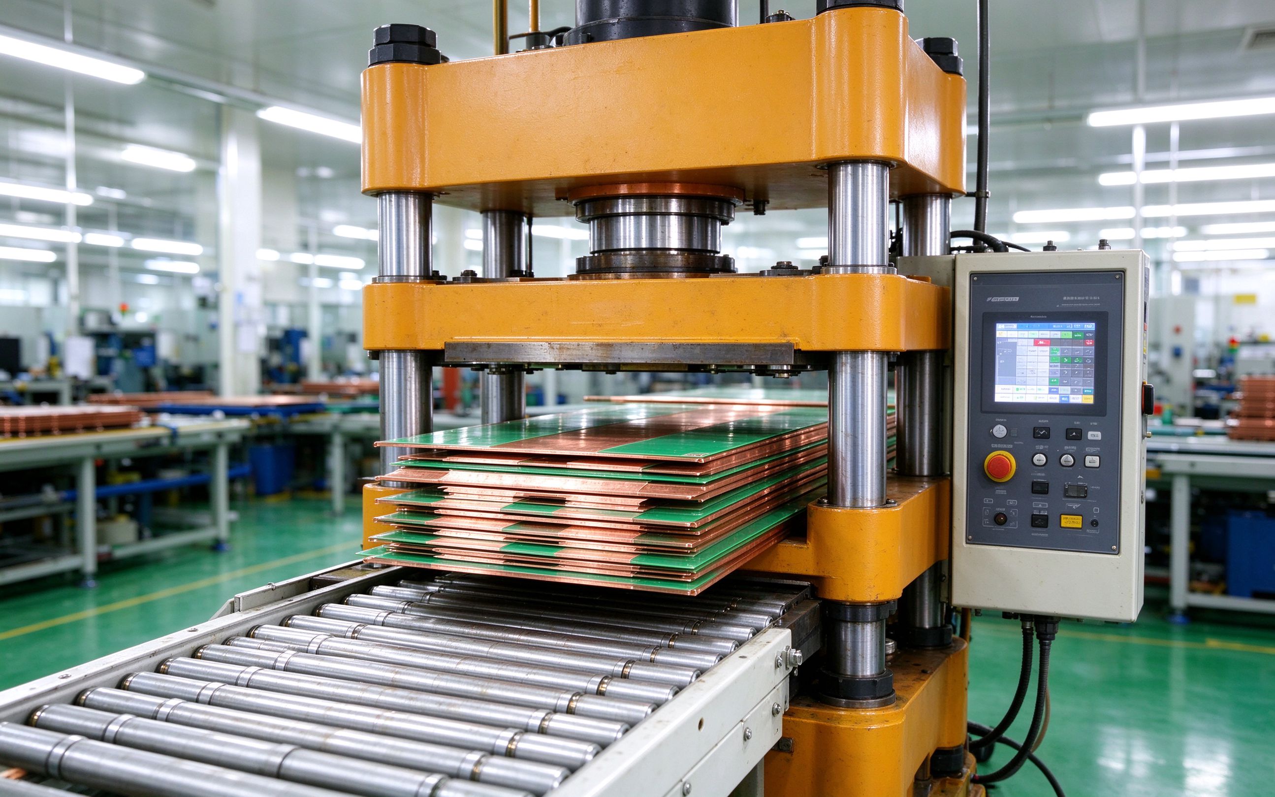
Most power-electronics teams eventually face the laminated-busbar make-vs-buy call: build
Read article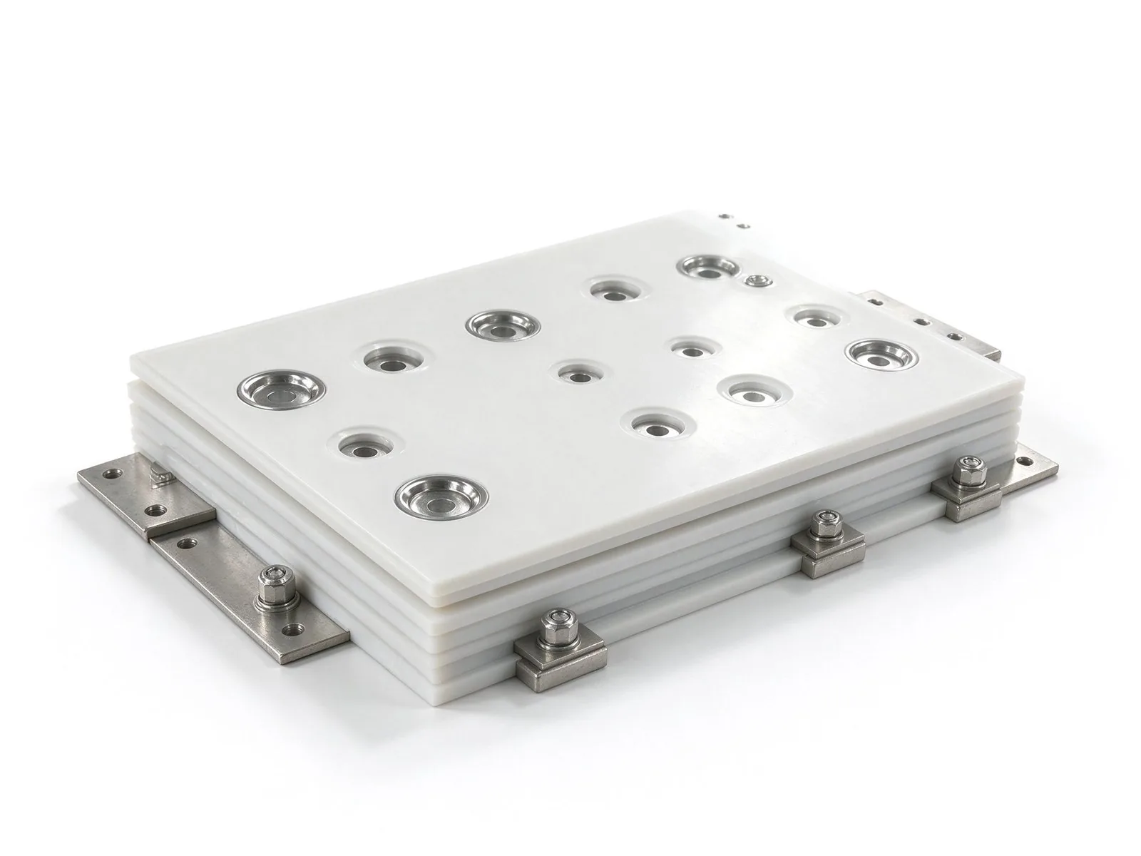
A 2-layer busbar is not automatically better than a 1-layer bar, and a 6-layer stack is no
Read article
David Osei is a product marketing engineer covering SHANYUAN's laminated busbar product lines. With 9 years in technical marketing for electrical components, he translates application requirements into product definitions, selection guides and technical content. He holds a B.Eng. in Electrical
Send the current profile, voltage class and terminal types — our engineers reply within one business day.
