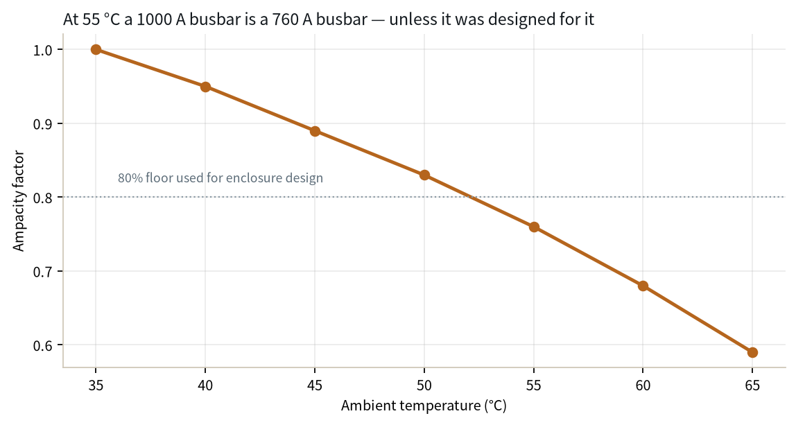
A 1000 A DC busbar sized at a 30 K rise over a 30 C reference does not carry 1000 A inside a 40 C BESS cabinet. It carries about 816 A once the rise budget is held. That single number is why the 2020-2022 two-hour BESS cohort now entering augmentation cannot just bolt on extra clusters: the copper, the tin plate, the bolted terminals and the fire-envelope have all aged five to seven years, and the original nameplate ampacity was never re-issued for the new duty cycle.
A 1000 A DC busbar sized at a 30 K rise over a 30 C reference does not carry 1000 A inside a 40 C BESS cabinet. It carries about 816 A once the rise budget is held. That single number is why the 2020-2022 two-hour BESS cohort now entering augmentation cannot just bolt on extra clusters: the copper, the tin plate, the bolted terminals and the fire-envelope have all aged five to seven years, and the original nameplate ampacity was never re-issued for the new duty cycle.
This page is an annual rolling data page: the 2026 edition, refreshed once a year as new market data is published.
BloombergNEF's October 2026 outlook puts global storage additions at 188 GW / 535 GWh in 2026, a record, with China, the US and Australia taking 62% of that volume (BloombergNEF, 2026). The American Clean Power Association / Wood Mackenzie Energy Storage Monitor, meanwhile, recorded a US Q2 2026 of 18.9 GWh, raising the national average duration from 2.8 to 3.5 hours as resource-adequacy contracts push systems longer (Wood Mackenzie, 2026). IEA counts global battery storage additions at 108 GW in 2025, up roughly 40% year on year (IEA, 2026).
None of those headline numbers is about new build alone. The cohort commissioned in 2020-2022 — the first wave of two-hour, 1P/2P LFP racks at 1500 V — is now four to six years into a 20-year financial life. Calendar aging, cycling fade, and the cheap-but-conservative PCS control of that era leave 15-25% headroom on the table. Operators are adding clusters, swapping to higher-capacity cells (280 Ah to 314 Ah and beyond), re-flashing PCS control to use the full 200-1000 V window, and in some projects replacing the PCS outright. That is augmentation, and it is the work order of 2026.
The DC busbar inside those containers was sized once, in 2021, for a 125 kW rack that now pulses 160 kW. The bars were never audited because the cells were the visible problem. They are about to become the visible problem.
Owners describe augmentation as adding cabinets. Electrically it is a different device. Three changes land on the bus:
None of these changes is subtle. Each one raises I²R heating in the bars, raises the peak short-time current the joints must survive, and raises the dielectric stress on the insulating film between positive and negative layers. If the original build used stationary-battery busbar interconnects rated for a 125 kW rack, the re-rated 160 kW rack has to be re-signed, not just re-torqued. We cover the cell-level connector side in large-cell ESS connection busbar design.
A fourth change, often missed, is the duration shift. The original 2-hour system was designed for 200-300 full-power cycles a year. Re-contracted for resource adequacy in California or Texas, the same rack now holds at 1C for 3.5 hours at a stretch, per Wood Mackenzie’s Q2 2026 observation that US average duration moved from 2.8 to 3.5 hours. Continuous load at 1C is not the same thermal duty as a 2-hour pulse: the bar sits at elevated temperature for six hours instead of 45 minutes, and the tin creep budget is spent far faster.
This is the calculation owners skip and then pay for in summer derate. SHANYUAN bars are rated at a 30 K temperature rise over a 30 C reference ambient, which puts the copper itself at 60 C under rated current. A BESS cabinet is not 30 C inside. Summer afternoon, after the HVAC has run at 70% for two hours, measured cabin air at the busbar is routinely 40-45 C.
Two choices, both documented in IEC 61439-1 busbar requirements and the ampacity chart:
| Strategy | Conductor cap | Allowed rise at 40 C cabin | Derating factor vs 1000 A |
|---|---|---|---|
| Hold conductor at 60 C (safe, conservative) | 60 C | 20 K | 1000 A x sqrt(20/30) ≈ 816 A |
| Allow conductor to 70 C (accelerated aging) | 70 C | 30 K | 1000 A (no derate, but film ages faster) |
The first row is the engineering answer. For a 1000 A-rated bar in a 40 C cabin, augmentation current above ~816 A is no longer within the original rise basis. Adding clusters without re-sizing the bar means the bar quietly runs at 65-70 C all summer, which is the exact condition that accelerates tin creep and dielectric aging in parallel.
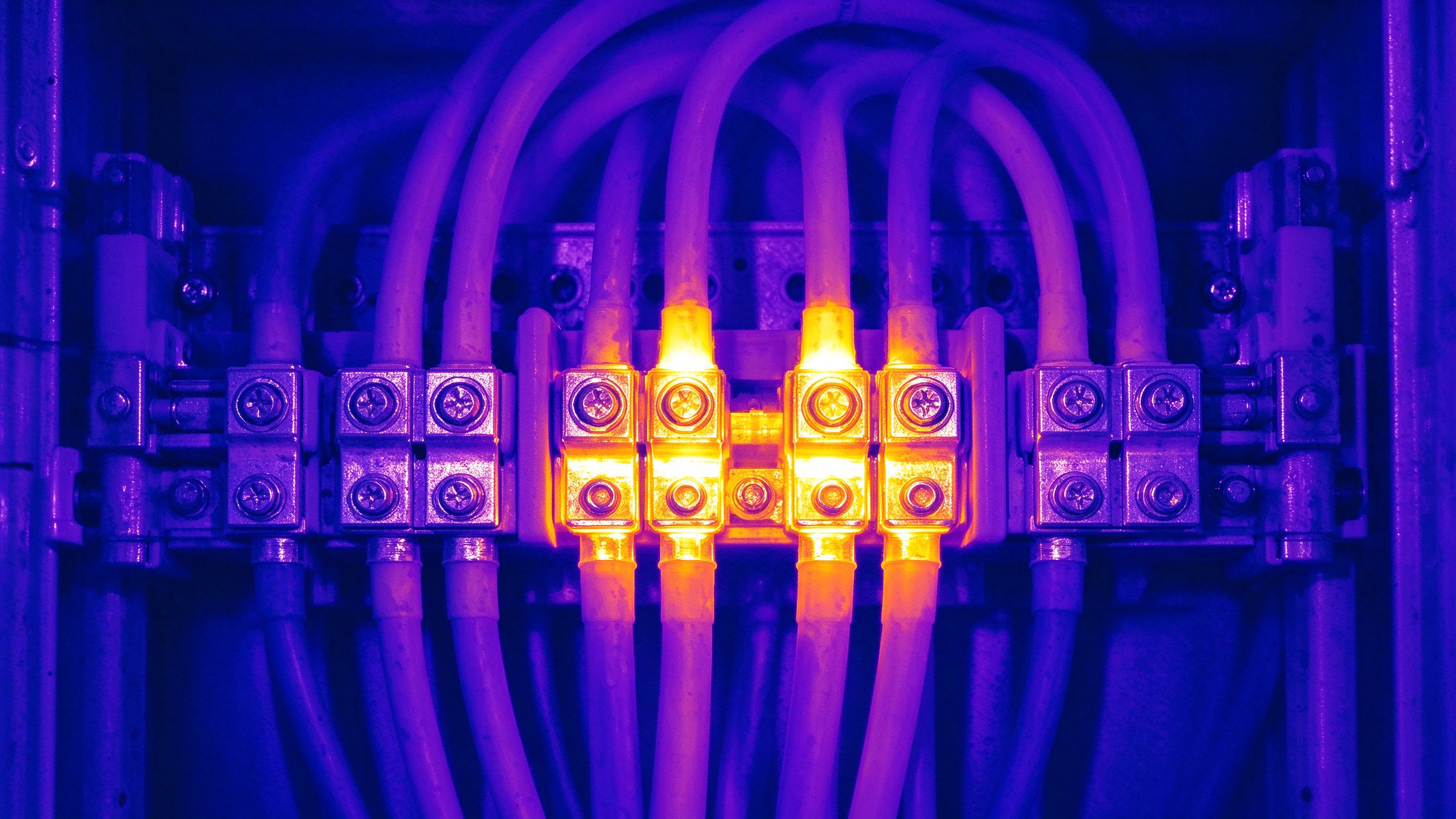
Bolted joints do not stay where they were torqued. Copper creeps under clamping pressure, Belleville washers relax, and daily thermal cycling (rack heats in the afternoon, cools overnight) pumps the joint through a few micrometres of slip. After five to seven years, measured contact resistance at a torqued M8 stud is typically 15-40% above commissioning values. Above 50% drift, the joint becomes a thermal runaway hotspot waiting for a summer peak.
The augmentation outage is the first controlled window in years to fix this. Sequence it in this order:
Do not retorque live. Do not trust a visual inspection. The IR thermography joint inspection article explains why the hottest joint in a rack is usually 30 cm from the broken washer.
Tin is soft. At 60-70 C conductor temperature, under the contact pressure of an M8 stud, a 5-12 micrometre tin layer thins at the asperities within the first two to three years, then keeps thinning. The joint still conducts because tin prevents copper oxide from forming — but the interface pressure shifts as the plating extrudes sideways. Fretting across the same few micrometres of daily slip oxidises the exposed copper at the edges of the contact patch.
What this means for a repower:
The interface physics — why contact resistance stays stable with tin even though tin itself is resistive — is laid out in our busbar contact resistance design guide. It is a three-minute read and it will save you from the common mistake of specifying silver plate on every joint.
Adding clusters often means running a new DC run from the PCS breaker to the new cabinet row. The engineering question is laminated busbar or copper cable in tray.
| Factor | Laminated busbar | DC cable in tray |
|---|---|---|
| Loop inductance | Low (interleaved Cu layers), good for PCS switching | 3-5x higher per metre |
| Space in cabinet | Dense, uses backplane volume | Flexible, uses tray space |
| Modification on site | Requires prefab section, outage window | Pull in a day, splice in field |
| Short-circuit withstand | High, braced for the new fault level | Needs checked against new fault current |
| Cost per kA-metre | Higher at small batch, lower at series | Lower at one-off |
The default after augmentation should be: keep the existing bar where it was sized with margin, and use cable for the new run to the added cluster row. Mixing the two means the inductance of the cable dominates the dv/dt seen by the PCS. We cover the trade in busbar versus cable selection and the low-inductance design implications in low-inductance design.
The hardest commercial constraint on an augmentation is not engineering; it is hours. A BESS site under contract may only take 48-72 hours of outage per quarter. On-site fabrication of a replacement laminated bar — CNC cutting, bending, tin plating, dielectric lay-up, hipot — cannot fit that window. Prefabricated, drop-in sections do.
The workflow that fits a 72-hour outage:
We build to this cadence on custom copper busbar projects and on blade-terminal busbar assemblies for ESS racks. The custom enquiry page walks through the drawing-to-ship cycle.
Sequencing on site matters as much as the part itself. Isolate the rack, lockout/tagout the DC breaker, verify zero volts at the busbar before breaking any stud, and keep the PCS auxiliary supply live so the BMS can log the re-energisation transient. Most busbar swap failures we hear about are not mechanical: they are rush jobs that skipped the 24-hour settling run, then blamed the bar for a joint that simply had not re-saturated its contact asperities yet.
The dielectric between positive and negative layers is the part of the bar that ages. PET film rated class B (130 C) loses tensile strength and dielectric strength roughly in step with Arrhenius acceleration — every 10 C rise halves service life. A bar designed to run at 60 C conductor that now runs at 70 C because of a 40 C cabin and no derating is, in insulation terms, halfway to the end of its life.
For a repower this matters in two ways. First, when you re-derate the bar to 816 A you are also bringing the film back to its design temperature — that is why derating, not upsizing the PCS, is the conservative choice. Second, when you add new layers to the bar (for a higher voltage window, say 1000 V to 1500 V class), the creepage and clearance distances must be re-checked against the new voltage — see creepage and clearance design. We also cover the Arrhenius aging math itself in today's companion article busbar thermal aging and Arrhenius life guide.
More parallel strings means more fault current. The original DC fuse size, the PCS interruption rating, and the bar's short-time current rating (Icw in IEC 61439-1) were sized for 2021 cell counts. Adding clusters raises the available DC short-circuit current by 30-80% depending on how many strings are paralleled.
Re-run three numbers:
The short-circuit withstand guide lists the calculation sequence; the standards resource page indexes the IEC and UL clauses owners cite in the engineering report.
The DC contactor inside the PCS is also on the list. Original 2021 contactors were rated for a certain breaking current and a certain number of operations. Augmentation raises both. If the contactor is not replaced in the same outage, its contact erosion accelerates and the next failure is a welded contactor on a high-current DC bus, which is a far more expensive outage than the busbar swap you just finished. Budget the contactor in the same work order.
UL 9540 lists the BESS as a system. UL 9540A is the test method that demonstrates cell-to-module-to-rack-to-enclosure thermal-runaway propagation control. Both are tied to a specific configuration. Augmentation — new cell chemistry, new cluster count, new DC bus cross-section, possibly a new PCS — is a configuration change. The listed system is no longer the system you have.
The fifth edition of UL 9540A, published 12 March 2025, tightened cell-to-cell propagation criteria, required at least one additional cell to enter thermal runaway during module testing, and added high-temperature protocols for new chemistries (UL Solutions, 2025). For a 2021 project certified to the 2019 edition, augmentation is the natural moment to re-evaluate against the current edition rather than grandfather the old report.
Owners should expect the AHJ (authority having jurisdiction) to ask for: an updated 9540A analysis covering the new cell chemistry, a re-run of the venting / gas spread analysis across the added cabinet row, and confirmation that the DC busbar insulation does not propagate flame. We walked through the regulatory side in ESS fire safety regulation and the busbar; the UL 9540A fifth-edition summary on the UL Solutions site is the citation to put in the report.
Gas detection and suppression interact with the augmented layout as well. Adding a cabinet row changes the vent path between the existing rack and the new one, and the 9540A vent-temperature measurement points from the original report no longer sit where the new gas plume will travel. Re-running the gas-spread analysis is not optional if the new row is within the enclosure footprint; it is the cheapest single line in the engineering report.
The 2020-2021 fleet was built through integrators who sourced bars from three or four shops. When the integrator is gone and the original bar drawing is on a dead engineer's email, the augmentation engineer faces a reverse-engineered part. That is the second-source problem in real life.
Two rules:
We support the drawing-to-ship cycle on quality documentation and specifications. If the augmentation project is at the RFQ stage, the contact page is the fastest route to an engineering review rather than a sales quote.
Augmentation work orders that skip this step tend to resurface three years later as mysterious joint failures on bars nobody remembers installing. The five hours spent sealing as-builts on outage day is the cheapest insurance in the project.
Pulled together for the engineer holding the outage work order. Run through this in order; do not skip steps because the site is behind schedule.
Augmentation pays for itself because it extracts 15-25% more revenue from an asset that already has grid connection. It stops paying the day a bar hot-spots a cabinet. The engineering above is the cheap part of that equation.
UL 9540A Ed.6 (published March 2026, effective January 2027) adds a large-scale fire test
Read article
The 500 Ah cell changes everything downstream: higher current per busbar segment, fewer bu
Read article
Aiko Tanaka is application engineering manager at SHANYUAN, with 11 years in applying laminated busbars to data centres, energy storage and new-energy systems. She leads application selection, custom-profile development and project delivery, and holds a B.Eng. in Electrical Engineering from the Univ
Send the current profile, voltage class and terminal types — our engineers reply within one business day.
