Most busbar quotations fail not on price but on paperwork. The assembly standard does not test the copper bar in isolation - it tests the bar inside a verified assembly. Understanding that distinction tells you which evidence to ask for, which claims to distrust, and why two suppliers quoting the same cross-section can be quoting two different risk levels.
Most busbar quotations fail not on price but on paperwork. The assembly standard does not test the copper bar in isolation - it tests the bar inside a verified assembly. Understanding that distinction tells you which evidence to ask for, which claims to distrust, and why two suppliers quoting the same cross-section can be quoting two different risk levels.
IEC 61439 is written for low-voltage switchgear and controlgear assemblies. It sets out how an assembly is designed, verified, tested and documented - not how an individual copper bar is manufactured. A busbar supplier therefore cannot be "IEC 61439 certified" in any meaningful sense. It can only supply components whose behaviour has been demonstrated inside an assembly that was verified under the standard.
This matters because procurement teams routinely ask for a certificate that cannot exist, and suppliers routinely issue one anyway. A genuine evidence pack looks different: it references the assembly type, the verification route used, the declared short-circuit and temperature-rise values, and the test house that witnessed them.
The practical consequence is that a busbar is only compliant in context. The same 3 mm copper profile can be perfectly adequate in a 630 A distribution panel and unacceptable in a 1600 A inverter cabinet, because the governing variables - airflow, enclosure volume, adjacent heat sources and joint quality - are properties of the assembly.
The standard separates design verification from routine verification, and the difference is not administrative. Design verification proves that a design type meets the requirements - once, on a representative sample or by calculation or by design rules. Routine verification proves that every unit leaving the factory matches that verified design.
A supplier that only offers a routine test report - continuity, hipot, a dimensional check - has proved nothing about temperature rise or short-circuit withstand. Those are design-level properties. Conversely, a supplier that offers only a type-test report and no routine records has proved the design but not the consistency of production.
Buyers should ask for both layers and check that they refer to the same design revision. A common audit finding is a type-test report dated before a material change - a thinner plating, a different insulation film, a new terminal supplier - with no re-verification note attached.
Design verification can be satisfied by testing, by calculation, or by design rules taken from the standard. Each route has a different cost and a different persuasive weight, and the choice is normally made by the assembly builder rather than the component supplier.
Testing is the strongest evidence: a worst-case sample is subjected to temperature rise and short-circuit tests in a laboratory. It is also the slowest and most expensive, which is why it is usually reserved for a new family or a significant change.
Calculation is accepted for many parameters when the method is documented and the inputs are traceable - conductor resistance, loss estimation, temperature rise by thermal model. It is fast, but it is only as good as the assumptions feeding it, and auditors will ask for those assumptions.
Design rules are the cheapest route: tables of clearances, creepage distances and minimum thicknesses that the standard permits you to apply without testing. They are also the route most often over-claimed. A supplier citing "design rules" for a 1250 A laminated bar with forced air cooling is usually citing something that does not apply.
Practical guidance: for a first article or a safety-critical assembly, ask for test data. For a repeat order inside an unchanged design, calculation plus routine records is defensible. For a custom profile that has never been type tested, ask which rule set was used and who signed it off - see the verification logic in our busbar design guide.
Temperature rise is the parameter that ties electrical design to mechanical design. The assembly is loaded at its rated current, and the rise above ambient is measured until it stabilises; the declared limit depends on the part of the standard being applied, the material of the conductor and the class of insulation in contact with it.
Two engineering consequences follow. First, the limit is not a single number: bare copper, tin-plated copper and insulated laminations behave differently, and the insulation class - not the copper - often sets the ceiling. Second, the measurement is of the assembly, so enclosure ventilation and the position of the bar inside the cabinet change the result.
This is why a supplier quoting "30 K rise" without stating the test arrangement should be treated cautiously. A 30 K figure measured on a single bar in open air is not comparable with a 30 K figure measured inside a closed cabinet with three neighbouring heat sources. Ask for the arrangement, the ambient, the stabilisation criterion and the instrument class.
Our own test sequence and the stabilisation rules we apply are described in the temperature-rise test guide; the design-side calculation is covered in the thermal management resource.
Two numbers describe short-circuit behaviour: the rated short-time withstand current, usually written Icw and expressed in kA for a defined duration, and the peak withstand current, Ipk, which captures the electromagnetic forces of the first asymmetric peak.
The busbar is not a passive participant here. The electromagnetic force between parallel bars scales with the square of the current and inversely with spacing, so a design that passes at 50 kA can fail mechanically at 80 kA without any change in cross-section. Support spacing, clamping, insulation thickness and terminal geometry all enter the calculation.
For laminated bars the failure mode is often delamination or insulation puncture rather than melting: the dielectric is compressed, the joint is stressed, and the weakest point is frequently the terminal block rather than the bar run.
When evaluating a supplier, ask for the declared Icw and Ipk values, the duration, the support spacing assumed, and whether the values were type tested or calculated. A declaration without those qualifiers is a catalogue number, not evidence. The mechanics are worked through in our short-circuit withstand guide.
Clearance is the shortest distance through air; creepage is the shortest path across an insulating surface. Both are functions of voltage, pollution degree and material group, and both are verified at assembly level because neighbouring components change the field.
The chain is only as strong as its weakest link. A laminated bar with excellent internal insulation can still fail verification because the distance from its terminal to the enclosure wall, or between two phases at the entry gland, was set by a panel builder working from a different table.
In practice, most clearance non-conformities appear at interfaces: where the busbar meets a fuse holder, where a phase crosses a neutral, where a temperature sensor cable runs across a live terminal. Component suppliers and panel builders each believe the other owns that gap.
Defining the interface explicitly - in the drawing, not in an email - is the cheapest fix. Our creepage and clearance design note gives the working method, and the partial-discharge resource explains why clearance alone does not guarantee a quiet dielectric at higher voltages.
Three material decisions dominate verification outcomes: conductor grade, plating, and insulation system. Copper grade affects conductivity and therefore loss and rise; plating affects contact resistance and corrosion behaviour at joints; the insulation system sets the temperature class and the dielectric margin.
Thickness is usually chosen for current, but it also sets mechanical stiffness and short-circuit behaviour. A profile that is 0.2 mm thinner may pass a current calculation and fail a force calculation - or pass both and fail a creepage check because the insulation layer was compressed.
The subtle risk is substitution. A supplier switching from C11000 to a lower-conductivity grade, or from tin to a thinner tin flash, changes the verified assumptions without changing the drawing number. Auditors call this an unapproved change, and it is one of the few things that can invalidate a type test retroactively.
Specify grade, temper, plating thickness in microns and insulation material by name, not by description. The copper versus aluminum comparison covers the conductivity trade-off, and laminated busbar construction shows how the layers are actually built.
A complete pack is short enough to fit in one folder and specific enough that a third-party inspector can follow it. In our experience it contains seven items: a drawing with revision and material callouts; a design verification index that names the route used for each parameter; type-test reports with laboratory identity and dates; routine test records for the shipped batch; a declaration of conformity referencing the assembly standard; a material traceability sheet linking copper heat numbers to the batch; and a change log.
Two of those items are routinely missing - the verification index and the change log - and they are the two that matter most in a dispute. The index tells an auditor where to look; the change log tells them whether the evidence is still valid.
Package them with the shipment rather than promising to send them later. Our quality documents page lists the standard set we issue, and the quality system overview explains how inspection points map to those documents.
Across supplier audits and incoming inspections, the same five findings recur. They are rarely catastrophic and almost always documentary or interfacial.
One: a type-test report that predates a material change, with no re-verification note. Two: a temperature-rise declaration without the test arrangement or ambient. Three: a clearance drawing that stops at the component boundary, leaving the interface undefined. Four: plating thickness specified as "standard" rather than in microns, making incoming verification impossible. Five: no link between the copper heat number and the shipped assembly, which breaks traceability exactly when a customer needs it.
Each has a cheap corrective action: a change-log discipline, a declaration template with mandatory fields, an interface drawing shared with the panel builder, a plating callout in microns, and a marking rule that survives encapsulation.
None of these require new equipment. They require someone to own the document, which is why they persist. Our related note on factory audits turns these five into interview questions.
Take the next quotation you receive and apply four questions. Which parameters were verified by test, which by calculation, and which by design rules? What are the declared temperature-rise and short-circuit values, and against which arrangement were they measured? Where does the component drawing hand over responsibility to the assembly drawing? And what happens to the verification if a material or process changes?
If the answers arrive as a document rather than an assurance, the quotation is comparable. If they arrive as a promise, treat the price as provisional.
SHANYUAN supplies laminated and bare copper busbars into assemblies verified by OEMs and panel builders, and supports that process with type-test reports, routine records and traceability on request. If you are preparing a verification file and need the component-side inputs, send the drawing and the assembly context through our contact form.
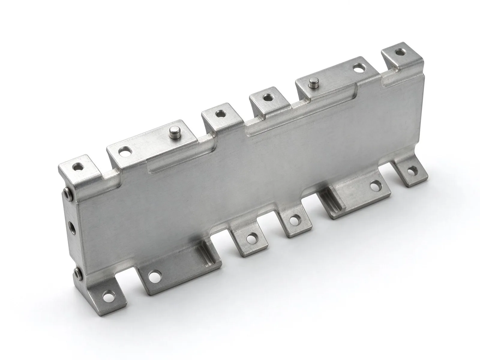
A practical guide to busbar continuous-current temperature-rise testing: applicable IEC li
Read article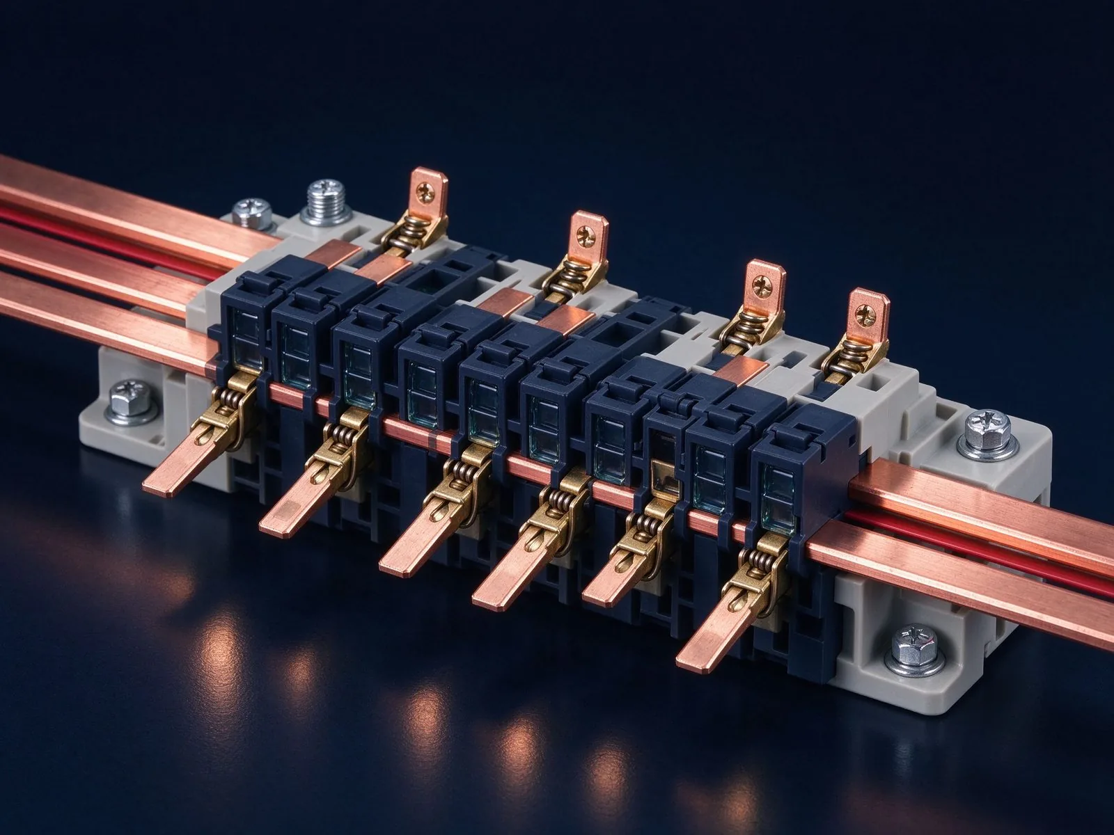
A short circuit is the busbar's worst moment: tens of kiloamps peak, forces in kilonewtons
Read article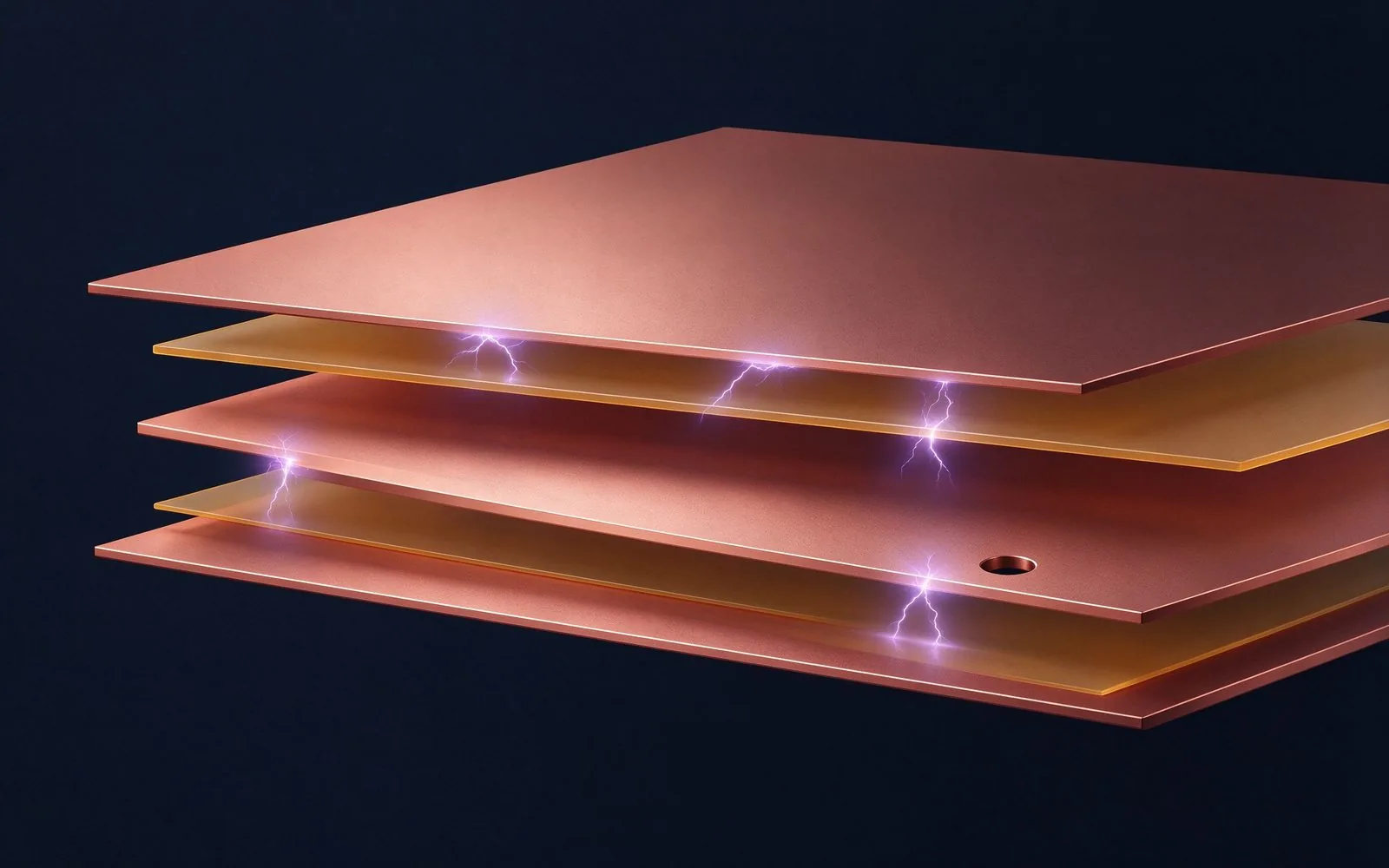
A busbar fails across a surface long before it fails through its insulation if the creepag
Read article
Sofia Lindqvist is a high-voltage test and partial discharge engineer with 8 years in dielectric qualification of laminated busbars. She runs IEC 60270 partial-discharge measurement, withstand-voltage and insulation diagnostics, and helped build SHANYUAN's in-house HV test lab. She holds an M.S
Send the current profile, voltage class and terminal types — our engineers reply within one business day.
