Custom stationary battery busbar and intercell links for flooded, VRLA, AGM and gel banks, plated to the cell chemistry. Request a sample.
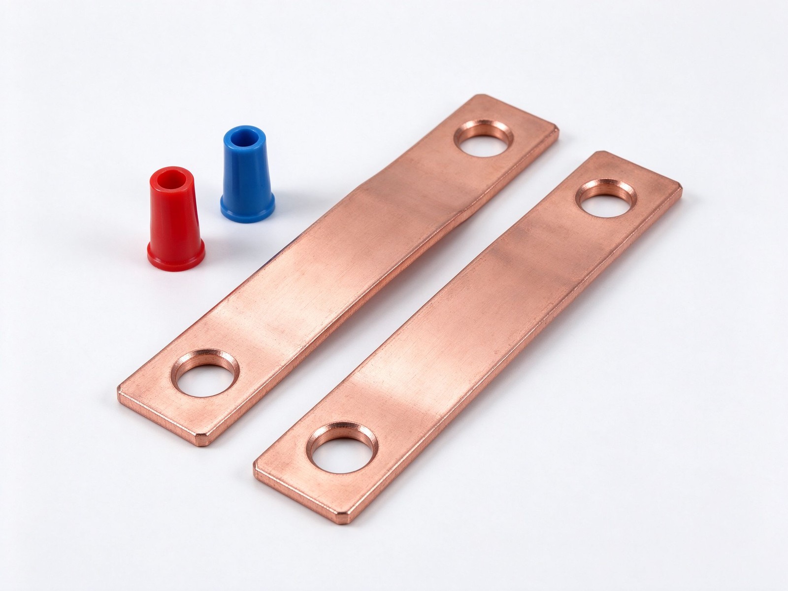
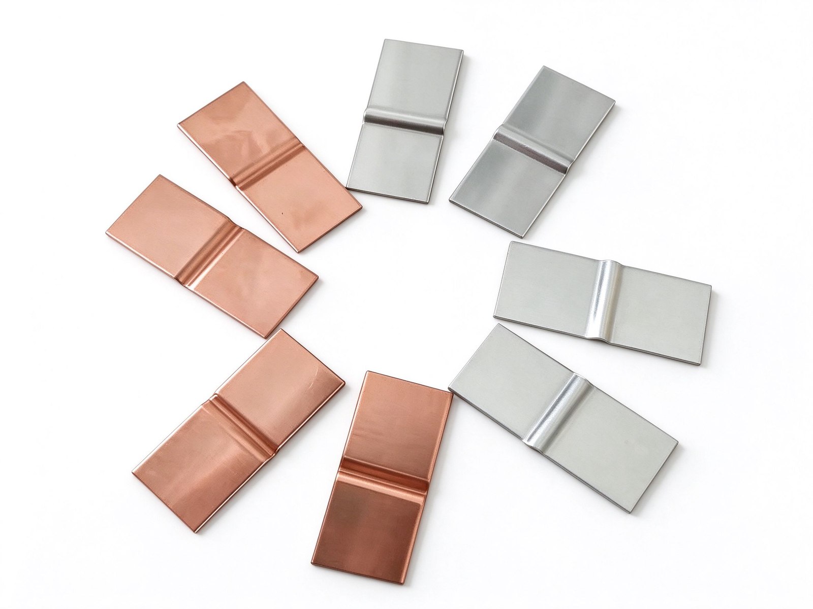
Product imagery: factory photo plus studio renders. The exact geometry, layers and terminals of your part follow your drawing.
Final values follow your drawing — this is the standard configuration of the family.
| Parameter | Value |
|---|---|
| Conductor | C11000 copper or aluminium flat intercell link bar |
| Cell chemistries | Flooded lead-calcium/lead-antimony; VRLA; AGM; gel |
| Plating | Tin, tin-lead alloy or pure lead, in-house, no setup fee |
| Joint style | Through-bolted or compression-mounted post links |
| Post fit | Red positive / blue negative insulating post caps available |
| Process | CNC punch, bend, mill, drill from start to finish |
| Order range | Prototype runs through high-volume production |
| SKU | SY-BB-111 |
Key characteristics of this product family.
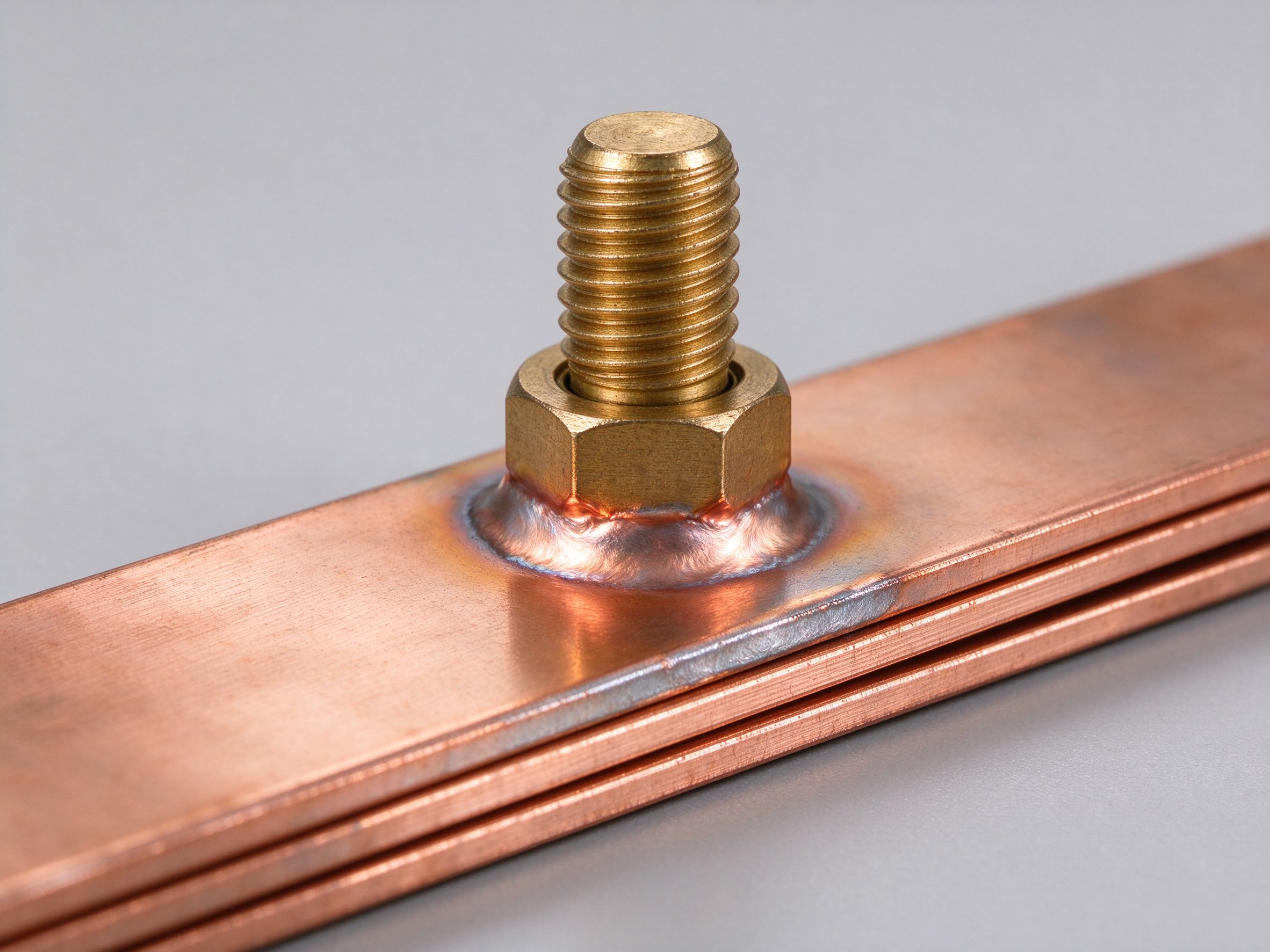
A stationary battery busbar is the flat rectangular link that joins one cell post to the next, stringing individual batteries into a bank of the required voltage and amp-hour rating. These links live inside battery rooms, UPS systems and central-office plants, and their reliability is measured in decades: a corroded or overheated link is the most common single point of failure in a battery string.
The connector is built for the cell chemistry it touches. Flooded wet cells use lead-calcium or lead-antimony plates and ask for lead or tin-lead plating on the link; sealed VRLA cells - lead-calcium and lead-antimony-selenium - run absorbent-glass-mat or gel electrolytes and pair well with tin-plated copper or aluminium links. Matching the plating to the chemistry is what keeps post interfaces free of oxide buildup under long float charge.
Plating options are tin, tin-lead alloy and pure lead, all applied in-house with no setup fee on plating - which means a small prototype run and a high-volume production run cost the same to plate. Production is CNC-based from start to finish, with several fabrication routes chosen by connector design and order volume, and every drawing passes a DFM review before any tooling is committed.
The applications span every installation where a battery bank is the last line of power: hybrid and electric vehicle interconnects, telephone central-office strings, emergency lighting, uninterruptible power supplies, continuous-process DC systems, operating controls, switchgear components and protective relay tripping supplies. Send the post pattern, float current and bank voltage, and our engineers will return a quote within one business day.
Flooded wet cells - lead-calcium or lead-antimony - sit in a liquid electrolyte atmosphere, so links use lead or tin-lead plating that resists the wet-cell vapours. Sealed VRLA, absorbent-glass-mat and gel cells float dry and pair well with tin-plated copper or aluminium links. The plating change between chemistries costs nothing extra: plating carries no setup fee, so prototyping in one finish and production in another is economical. Compare the related battery post straps and copper battery link pairs.
Send the post spacing, cell jar outline, float current and bank voltage; we map the link geometry, bend radius and hole pattern, then run the part through CNC punch, bend, mill and drill routes chosen for your volume. A DFM review before tooling catches interference with post caps and rack edges early. Production spans ten-piece prototypes to high-volume runs through the custom battery busbar service - and for high-current module-level builds, see high-current battery module busbars.
Stationary banks carry the loads that must not stop: UPS in datacentres, telephone central offices, emergency lighting, continuous-process DC systems, operating controls, switchgear and protective relay tripping supplies. A corroded link fails the whole string, so plating fit, contact torque and predictable voltage drop are specified up front. Explore the application context in energy storage systems and datacenter power.
A stationary battery busbar lives most of its life at float current, which means its heating table is dominated by the short discharge events rather than the standby state. The table lists typical link rises for a battery bank interconnect busbar UPS string, quoted against the battery-room air.
| Bank Mode | Link Current | Link Section | Typical Rise Above Room Air | Note |
|---|---|---|---|---|
| Continuous float standby | 15 A | 2 × 2 mm × 25 mm (100 mm²) | ≈ 4 K | Links run near ambient |
| UPS discharge, 15 min | 400 A | 2 × 2 mm × 25 mm | ≈ 22 K | Short event, no steady heating |
| Annual 30-min load test | 320 A for 30 min | 2 × 2 mm × 25 mm | ≈ 26 K | Inside plating limit |
| Rectifier ripple component | 30 A RMS | 2 × 2 mm × 25 mm | ≈ 5 K additional | Sits on top of the float rise |
| Cold room at 10 °C | 400 A | 2 × 2 mm × 25 mm | ≈ 19 K peak | Room cold, headroom large |
These estimates hold for either a tin-plated VRLA AGM gel battery connector or a tin lead plated battery strap: the plating changes the corrosion behaviour, not the rise. The ripple row matters because rectifiers leave an AC component on the DC link, and that component heats the link a little even while the bank floats. Room temperature, discharge minutes and bank voltage are what we size from; datacenter UPS battery rooms and their link layout are described under datacenter power applications, and finish choice for wet-cell vapours is covered in lead and tin-lead plating notes.
Stationary banks are specified for decades, so the cycle-life table here runs on years rather than on fast-charge counts. The typical expectations below follow the room environment, because room climate — not discharge minutes — decides how fast the link and its plating age.
| Service Environment | Swing per Year | Typical Service Life | Inspection Cadence |
|---|---|---|---|
| Air-conditioned telecom hall | 3–6 K daily | 20+ years | Torque check at 5 years, then per policy |
| Warehouse-class plant room | 8–12 K seasonal | 15–20 years | Link corrosion walk-down yearly |
| Outdoor cabinet site | 15–25 K seasonal | 10–15 years | Tin-lead face inspection every 3 years |
| Coastal high humidity | 10–18 K | 12–16 years | IR drop trend per intercell link |
Long service life comes from keeping the contact face stable: torque, plating and voltage drop are the three numbers walked down on site. Rising IR drop, a dull tin-lead face, or a post cap that has started to swell are the three signals that retire a link before its years run out. Indoor banks age on room climate; outdoor cabinets age on sun, rain and swing, which is why the inspection cadence shortens outside. The 20-year figure assumes the room stays within its rated band and the torque policy is followed; a bank that drifts outside its room band ages faster, regardless of plating. Drier telecom halls age links slower; damper coastal rooms age the plating faster, which is why the inspection cadence tightens by environment. Each environment row narrows the inspection cadence, not the expected life itself, so the 20-year target holds across all four rows. Stationary backup builds of this kind are grouped under stationary backup power systems, and the measurement practice for torque and IR drop is laid out in intercell connection guidance.
Where this busbar configuration earns its place.
Where this busbar configuration earns its place.
Where this busbar configuration earns its place.
Where this busbar configuration earns its place.
Where this busbar configuration earns its place.
Where this busbar configuration earns its place.
Your drawings reach the engineers who build the part.
Design risks flagged when changes are cheap.
Test records per lot, CoC and PPAP on request.
Drawing to delivered production parts, one supplier.
From spec review to shipped, tested parts — one accountable supplier.
Straight answers from the engineering team.
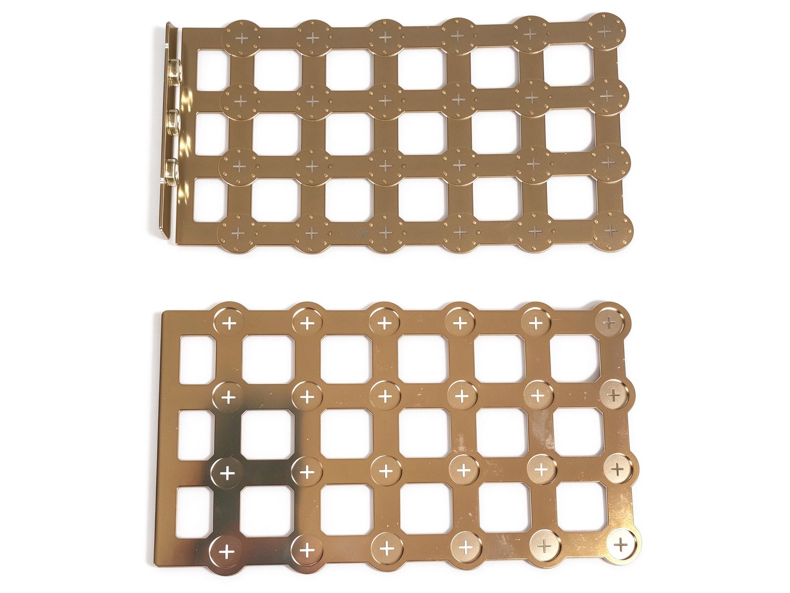
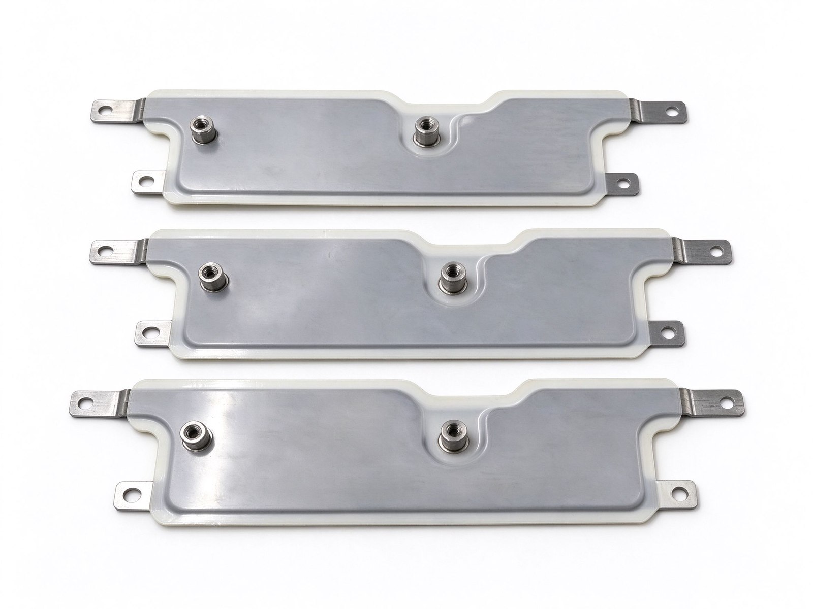
Every SHANYUAN busbar is custom, but the power circuits they connect recur across markets. Three typical ones — send us yours and we will point to the right stack-up.
Tight, low-inductance links between the battery source and traction inverters, fully edge-sealed for 400–800 V platforms.
Commutation-loop connections from DC-link capacitors to IGBT bridges, designed against switching overshoot V = L × di/dt.
Converter DC links built for rising bus voltages toward 1500 VDC, with creepage and partial-discharge margins included.
Construction, dielectric selection and current capacity basics.
Read the busbar design guideLayers, terminals, dielectrics and mounting are all configurable. Send us your spec for DFM review and a quotation within one business day.
