Every bolted busbar joint is a small resistor in series with a large conductor. At full current that resistor produces heat, and when it grows — through oxidation, fretting or torque relaxation — the heat grows with the square of the current. Specifying contact resistance explicitly, measuring it correctly and controlling the plating and torque levers is the difference between a joint that lasts decades and one that fails in the field.
Every bolted busbar joint is a small resistor in series with a large conductor. At full current that resistor produces heat, and when it grows — through oxidation, fretting or torque relaxation — the heat grows with the square of the current. Specifying contact resistance explicitly, measuring it correctly and controlling the plating and torque levers is the difference between a joint that lasts decades and one that fails in the field.
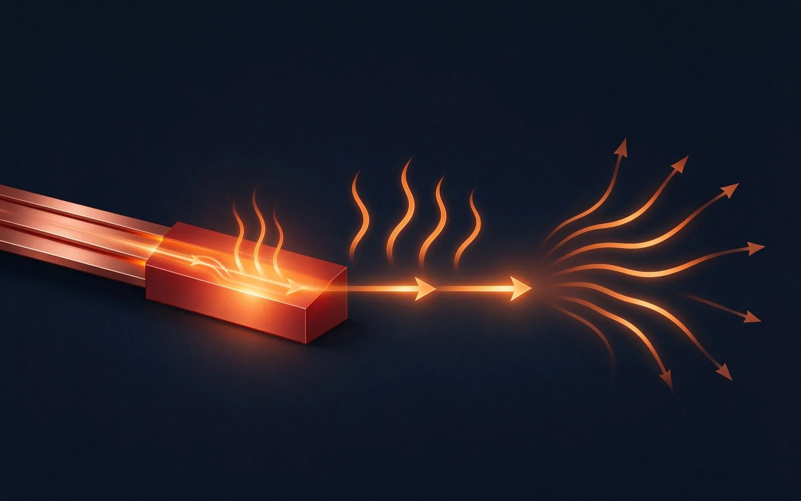
A bolted joint carries current through microscopic contact spots, not the full face area. Those spots — the a-spots — constrict the current, and the constriction plus the surface film resistance is the contact resistance. At 1000 A, even 0.1 mΩ produces 100 W of heat; at 2000 A the same joint produces 400 W. Temperature rise follows the square of the current.
That is why voltage drop and power loss analysis starts at the joints, and why the 30 °C temperature-rise anchor used at SHANYUAN includes the joint, not just the conductor.
Two terms make up contact resistance. Constriction resistance comes from current funneling through the a-spots — smaller, fewer or oxidized spots raise it. Film resistance comes from the surface layer between the metals: tin oxide, copper oxide, grease or plating wear products. Both grow with time; both shrink with plating quality and contact pressure.
The engineering lever is to maximize the effective contact area: flat, clean, well-plated surfaces, adequate clamp force, and a plating that stays conductive under load. The ampacity and temperature-rise chart assumes a controlled joint — the assumption has to be manufactured, not assumed.
Plating decides the film resistance term. Tin is the workhorse: soft, oxidation-tolerant in the operating range, and forgiving of micromotion. Nickel adds a hard barrier against copper migration and base-metal oxidation but has higher intrinsic resistivity. Silver gives the lowest resistance and best high-frequency behavior but costs more and tarnishes in sulfur environments.
Thickness is a specification decision, not a default: plating corrosion guide covers the mechanism; the RFQ should state the minimum thickness on contact surfaces and the plating standard, with certificates per lot.

Roughness determines how much of the face actually touches. Two mirror-smooth, flat faces can have nearly full-face contact; rough or bowed faces reduce the a-spot area and concentrate current. Flatness of the busbar face at the joint, burr removal from stamped edges and clean assembly conditions all feed the contact budget.
Stamped busbar edges need deburring before plating — a process step that shows up in field reliability long before it shows up in the quote. The fabrication tolerances guide states what to hold and measure.
Clamp force converts roughness into contact. Too little force: small a-spot area, high resistance. Too much force: plating squeeze-out, thread yield, base-metal exposure. The M6 and M8 stud terminals standard on SHANYUAN busbars are torque-specified, with washers and lock features where vibration is present.
Torque alone is an imperfect proxy for clamp force (friction varies), which is why critical joints get torque-plus-angle control or direct force verification. Vibration design and bolt relaxation are covered in the bolted joint guide.
Contact resistance and temperature form a feedback loop: resistance heats the joint, heat accelerates oxidation and relaxation, oxidation raises resistance further. The 30 °C rise anchor keeps the loop benign; pushing a joint to 60–70 °C rise accelerates the ageing curve and moves the failure point years earlier.
Design for the joint, not just the copper: thermal simulation and thermal management design should include the bolted interface as a heat source with its own resistance value.
Contact resistance is measured with a micro-ohmmeter using a four-wire (Kelvin) connection, at a defined current, with the voltage sense leads placed across the joint — not across the whole busbar. The measured value must be normalized to the joint area or stated per joint, and compared against a documented acceptance limit.
Field measurement adds a second challenge: where to place the probes. The maintenance and troubleshooting guide covers probe placement and the acceptance criteria for in-service joints.
Three ageing mechanisms attack the joint. Oxidation adds film resistance at the exposed interface. Fretting — micromotion between the faces under thermal cycling or vibration — grinds the plating and generates wear debris that insulates. Torque relaxation reduces clamp force and shrinks the a-spot area. All three raise resistance over time; the rate depends on plating, force and duty.
Accelerated testing — thermal cycling, vibration and current-cycling with periodic resistance measurement — turns ageing from a surprise into a curve. The thermal cycling reliability guide shows the test method and the pass/fail logic.
Good bolted joints land in the tens-of-micro-ohm range per joint for typical busbar sizes — values that depend on area, plating and clamp force, so targets must be geometry-specific rather than absolute. The practical rule: specify a resistance ratio or maximum rise at rated current, and verify it on every lot sample.
Instead of chasing an absolute number, specify: measured joint resistance at rated current, the resulting temperature rise, and the drift allowed after thermal cycling. That trio is auditable and comparable across suppliers.
Demand per-lot evidence: plating thickness certificates on contact surfaces, torque or clamp-force verification records, four-wire joint resistance measurements at rated current, temperature-rise data, and thermal-cycling or vibration test summaries for the connection method. Batch traceability ties each joint back to its process record.
SHANYUAN's quality system maintains these records per lot and ships them with the product — the documentation is part of the deliverable.
Discolored or charred insulation near a joint: resistance runaway. Loose fasteners after thermal cycling: torque relaxation or CTE-driven loosening. Black or worn contact surfaces: fretting or oxidation. Intermittent faults under load: contact pressure loss with temperature. Each signature maps to a design or process cause that the manufacturing side can close.
Failure analysis is a loop back to design: the failure modes guide catalogs the patterns and the fixes.
Specify plating material, thickness and standard on contact faces; define surface finish and deburr requirements; set torque or clamp force with lock features; confirm flatness and edge condition; define the four-wire resistance test, acceptance value and sample plan; and require drift limits after thermal cycling. Each line belongs in the RFQ, not discovered at first failure.
For a joint designed rather than guessed, start with the terminal connection guide and send the full context to the contact page for a documented proposal.
SHANYUAN manufactures bolted-joint busbars with controlled processes: C11000 copper, tin-plated contacts with thickness certification, M6/M8 stud terminals, torque-controlled assembly where supplied, and per-lot four-wire resistance and temperature-rise records — on 1–6+ layer laminated builds up to the ~1000 A class.
Engineering review and quotation respond within one business day; custom designs start from your drawing and duty profile.
The plating on a busbar contact is a corrosion strategy as much as a conductivity play. Ti
Read article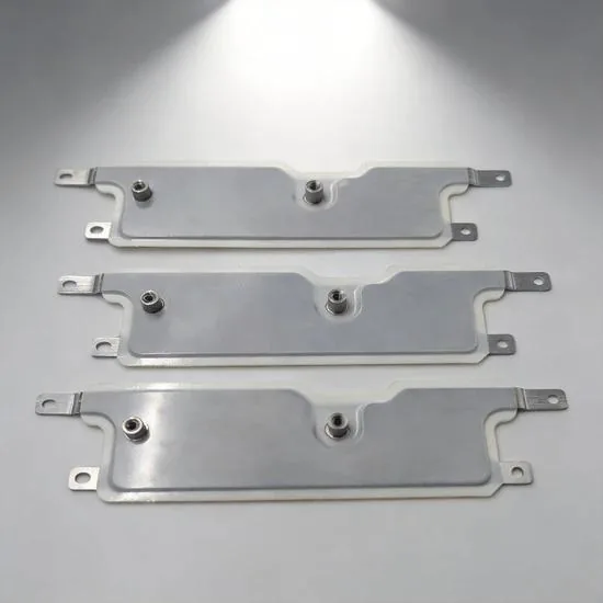
Voltage drop in a busbar decides whether the far end of a distribution system sees enough
Read article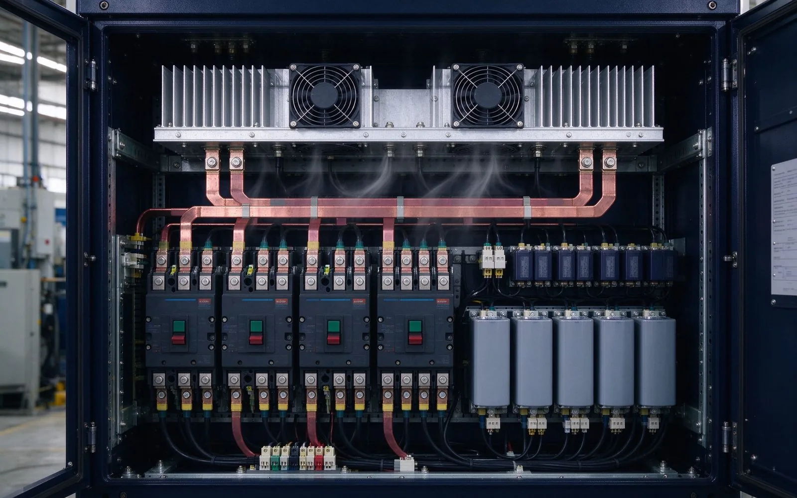
A busbar's thermal design decides its real current rating. Natural convection sheds ~50 W/
Read article
Daniel Richter is the chief electrical engineer at SHANYUAN Laminated Busbars, with 15 years in laminated busbar design and current-carrying systems. He leads electrical dimensioning, DC-link layout and thermal simulation for power converters, EV platforms and HVDC stations, and holds an M.Sc. in El
Send the current profile, voltage class and terminal types — our engineers reply within one business day.