A laminated busbar can pass every hipot test at shipment and still fail eight years later — not from a short circuit, but from a dielectric film that has slowly oxidised until its breakdown voltage falls to half of new. That degradation follows Arrhenius: every 10 °C rise roughly halves polymer life, yet the rule is only an engineering approximation. This guide translates IEC 60216 temperature index, UL 746B RTI and accelerated-aging regression into a 20-year life claim, with the test matrix, the 50%-retention end-points, PD coupling and the ambient derating practice engineering teams need.
A laminated busbar can pass every hipot test at shipment and still fail eight years later — not from a short circuit, but from a dielectric film that has slowly oxidised until its breakdown voltage falls to half of new. That degradation follows Arrhenius: every 10 °C rise roughly halves polymer life, yet the rule is only an engineering approximation. This guide translates IEC 60216 temperature index, UL 746B RTI and accelerated-aging regression into a 20-year life claim, with the test matrix, the 50%-retention end-points, PD coupling and the ambient derating practice engineering teams need.
A laminated busbar is a stack of copper foils separated by a thin dielectric film — PET, Nomex or a B-stage DLF — bonded under heat and pressure. The copper ages negligibly over 20 years; the adhesive and the film do not. Every hour the laminate sits above 90 °C, the polymer chain slowly oxidises, the glass-transition edge creeps downward, and the bond between copper and film weakens. Most field failures of laminated busbars are not short circuits at turn-on. They are slow, predictable insulation degradations: a creepage path that forms after eight summers in a sealed cabinet, a partial-discharge (PD) level that climbs from 5 pC to 200 pC by year twelve, or a bond-line peel strength that falls below the assembly's clamping threshold.
This article turns that degradation into numbers. It follows the IEC 60216 method — temperature index (TI), relative thermal endurance graph (RTE), Arrhenius regression — and shows how to translate a material data sheet into a 20-year service claim for a multi-layer laminated busbar. It is the companion to the thermal-cycling article: that one covers reversible, cycle-driven fatigue; this one covers steady-state, temperature-driven chemical aging.
IEC 60216 (parts 1, 2, 5 and 6; current editions 2018–2023) is the international method for ageing electrical insulating materials. Its output is two numbers. The Temperature Index (TI) is the temperature — in °C — at which the material reaches a defined end-point in 20,000 hours (about 2.3 years). The Relative Temperature Index (RTI), used in North America under UL 746B, is the equivalent continuous-use temperature for the same 20,000-hour end-point, derived against a reference material rather than an absolute clock.
The Relative Thermal Endurance Graph (RTE) is the straight-line regression of log(life) against 1/T (Kelvin), drawn through at least three ageing temperatures. Extrapolating that line to 20,000 h gives TI; extrapolating to the customer's service temperature gives predicted life. The method deliberately uses an Arrhenius plot because polymer oxidation is thermally activated.
| IEC 60085 class | Max. °C | Typical role in laminated busbars |
|---|---|---|
| Y / A | 90 / 105 | Not used for laminated dielectric |
| E | 120 | Ordinary PET, low-voltage signal busbars |
| B | 130 | Heat-stabilised PET, general industrial |
| F | 155 | DLF / epoxy-glass, inverter dc-link |
| H | 180 | High-grade DLF, traction converters |
| C | ≥180 (commonly 220) | Nomex aramid, polyimide film |
Note that a material's class is not the laminate's class. A dielectric film rated Class B can be the weakest link in a Class F assembly if the adhesive or the edge seal ages faster than the film itself.
The Arrhenius model for polymer life is L(T) = A · exp(Ea / (k·T)), where L is time to end-point, Ea is the activation energy of the dominant degradation reaction (in eV), k is Boltzmann's constant (8.617 × 10⁻⁵ eV/K) and T is absolute temperature. Take a worked example. For a filled PET laminate, published Ea values cluster near 1.0 eV. At 100 °C (373.15 K) the predicted life is L₁₀₀. At 120 °C (393.15 K):
L₁₀₀ / L₁₂₀ = exp[(1.0 / 8.617e-5) × (1/373.15 − 1/393.15)] ≈ exp(1.58) ≈ 4.9.
In words: a 20 °C rise cuts predicted life by roughly five-fold. If the same laminate is specified for 20 years at 100 °C, it survives only about 4 years at 120 °C, and roughly 1.8 years at 130 °C. That is why a hotspot 15 °C above the design average is a 5-to-1 life penalty, not a modest margin issue.
The same calculation from 120 °C to 155 °C (Class F ceiling) gives L₁₂₀ / L₁₅₅ ≈ 11.2 — a Class B film pressed into Class F service is essentially a consumable. Copper conductor losses and skin effect do not change this; they only set the temperature that feeds the Arrhenius equation.
To use the model on a real project, pull Ea from the supplier's IEC 60216 report rather than assuming 1.0 eV. PET laminates typically report Ea between 0.8 and 1.2 eV; Nomex systems cluster near 1.1–1.4 eV; DLF epoxy adhesives can run 0.7–1.0 eV because hydrolysis — not oxidation — is the dominant reaction at moderate temperatures. Feed the measured Ea, the measured hotspot T and the 20,000-hour TI into the same log-linear regression. The 20-year service temperature then falls out directly: solve L(T)=20 years for T. For a 1.0 eV system with a TI of 130 °C at 20,000 h, that service temperature lands near 92–95 °C — a useful rule check against the derating numbers in Section 10.
The “10 K half-life rule” — every 10 °C rise halves insulation life — is the field engineer's shorthand. It is not a law of nature. Rearranging the Arrhenius equation, the rule implies an activation energy of about 0.85 eV at 100 °C, rising to roughly 1.0 eV at 130 °C. In other words, the rule is calibrated for class B polymers in the 80–120 °C band, and it drifts outside that band.
Use the 10 K rule for rough planning, but require a measured Ea from the supplier's IEC 60216 test report for any contract that promises 20 years. The temperature-rise test guide shows how the steady-state hotspot temperature is measured; this article shows what that temperature costs in life.
Three dielectric films dominate laminated busbar construction. The table below compiles typical IEC 60085 classes and UL 746B RTI values from current material data sheets and supplier literature.
| Film | Chemistry | IEC class | Typ. TI / RTI | Busbar use |
|---|---|---|---|---|
| PET (Mylar-type) | Polyester | E (120) / B (130) heat-stabilised | TI 105–130 °C; RTI 105–130 °C | Signal and low-voltage dc-link busbars |
| Nomex 410 | Meta-aramid paper | C (220 °C class) | RTI ~180–200 °C | Traction, furnace, high-temp converter |
| DLF (B-stage dielectric laminate film) | Epoxy / glass-reinforced | F (155) / H (180) | RTI 150–180 °C | Power-electronics dc-link, high-ampacity stack |
These are typical ranges, not guarantees for a specific lot. The RTI on a DuPont Nomex 410 sheet, a polyester PET sheet and a DLF sheet differ by 10–20 °C depending on thickness, filler and cure. Always pull the actual UL yellow card or the supplier's IEC 60216 test report — filed in your quality document package — before naming a class on the drawing. The dielectric selection guide covers the voltage, thickness and cost trade-offs that sit on top of thermal class.
IEC 60216 and UL 746B both define end-point as the moment a measured property drops to 50% of its initial value. Three properties are tracked in parallel for a laminated busbar.
Short-time step-up breakdown (per IEC 60247 / ASTM D149 style) across the film. A 50% drop means the insulation can no longer withstand the system's impulse and ac over-voltage margins. For a 1.5 kV dc-link busbar, a fresh film may break at 40–60 kV/mm; end-point near 20–25 kV/mm is the trigger.
Dog-bone tensile on aged specimens. Brittleness shows as elongation at break collapsing from 70% to below 20%. This predicts edge cracking in service.
90-degree peel of copper from film. A fresh DLF laminate reads 4–8 N/cm; end-point near 2–3 N/cm means the bond can no longer survive bolt torque and thermal cycling. This is often the first property to hit 50% and is therefore the controlling one for laminated busbars.
Track all three; report the worst. The insulation testing guide covers the bench methods, sample conditioning and acceptance numbers.
To derive a TI or verify a 20-year claim, run a multi-point hot-air oven ageing study. The protocol below follows IEC 60216-2 and IEC 60216-6 (fixed-time-frame method).
| Parameter | Minimum per IEC 60216 | Recommended for laminated busbar |
|---|---|---|
| Ageing temperatures | 3 points | 4 points: e.g. 155, 175, 195, 215 °C |
| Lowest-point life | ~2,000 h | ~3,000 h (stable regression) |
| Highest-point life | ~100 h | ~200 h (avoid charring and mechanism change) |
| Sampling per pull | ≥5 specimens | 5–8 specimens, 3–4 pulls per temperature |
| Properties measured | 1 | breakdown, tensile, peel, PD |
| End-point | 50% retention | 50% on all three; report the controlling curve |
Plot log-time-to-endpoint against 1/T for each property. The slope gives Ea; the intercept at 20,000 h gives TI. A valid regression needs at least three points on a straight line — if the low-temperature point bends off the line, a new degradation mechanism has appeared and the Arrhenius model cannot be extrapolated through it. The quality system at the busbar shop should hold the raw data, the oven calibration certificates and the regression spreadsheet for every qualified dielectric lot.
Run the specimens in forced-air ovens held to ±2 K, with the rack load balanced so no laminate touches the wall. Use the same copper thickness, film lot and cure cycle as production — coupons made from lab prep material over-estimate life by a factor of two or more. Condition specimens at 23 °C and 50% RH for 24 h before every pull, and run a control batch measured at t=0. The regression spreadsheet should show log-life versus 1/T in Kelvin, with R² above 0.95 for each property. If R² drops below 0.9, the temperature points straddle a mechanism change — add a point between them rather than forcing the line.
Steady thermal ageing does not reduce breakdown voltage uniformly. It creates voids at the copper–film interface, releases volatile cure by-products, and raises the dielectric loss factor. Above ~4 kV/mm ac, those voids become partial-discharge sites. IEC 60270 defines the PD measurement (pC) and the test setup; a laminated busbar that starts at <5 pC at 1.2× rated voltage can drift to 100–500 pC after 1,000 h at 180 °C even before the breakdown voltage hits 50%.
The coupling matters because PD itself accelerates ageing: each discharge erodes the film chemically (corona by-products, ozone) and thermally (micro-sparks). A laminate that ages slowly at 120 °C with no PD can age 3–5× faster if a void forms at 140 °C under 6 kV. This is why the partial-discharge-free design article requires edge clearance, corona grading and void-free lamination — design choices that add years more than any film upgrade. After aging, always re-measure PD before declaring end-point; a clean breakdown number with rising pC is a failed laminate.
The copper in a laminated busbar is usually within 5 °C of uniform temperature. The hotspot is not mid-span. It is at the terminal stud or bolted joint, where contact resistance adds I²R heating and heat sinking is poorest; at the laminate edge, where the film overhangs the copper and cannot conduct heat into the bar; and behind a mounting bracket or a plastic cover that traps hot air.
Thermography under rated current — the method in the IR thermography joint inspection guide — typically shows terminal temperatures 10–25 K above the copper mid-span. That 15 K delta is exactly the life-killing gap from Section 3. Use the hotspot temperature, not the average copper temperature, for the Arrhenius calculation. If the hotspot runs 115 °C while the mid-span averages 95 °C, the laminate life is set by 115 °C, not 95 °C.
SHANYUAN rates its laminated busbars by a 30 K temperature rise over a 40 °C ambient reference. IEC 61439-1 (edition 3.0, 2021) sets terminal rise limits of 70 K for copper terminals and 65 K for aluminium, referenced to a 35 °C mean ambient. Both references break down in real enclosures: a sealed drive cabinet in Shandong or Arizona runs a 45–55 °C summer mean.
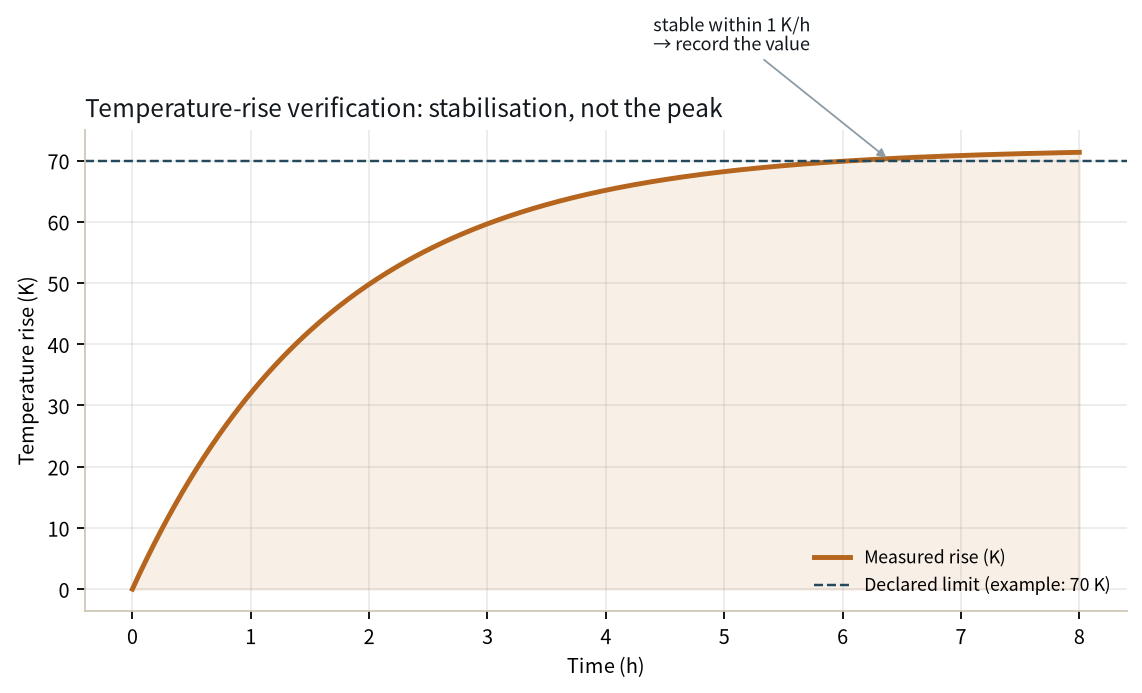
Practical rule: at 55 °C ambient, cap the terminal rise at 25 K (not 30 K) so the film hotspot stays below 95 °C for a PET Class B laminate, or below 125 °C for a DLF Class F laminate. Current must be derated by roughly 15–25% versus the nameplate. The thermal management resource page walks through the calculation; ventilated enclosures and forced air recover about half that margin. Long-run upper temperatures are typically 15–20 °C below the material's TI, with the largest margin reserved for the terminal hotspot.
Two practical checks close the derating loop. First, measure the enclosure's summer steady-state ambient with a datalogger for one week — do not rely on the nameplate 40 °C assumption. Second, compare the measured hotspot against the dielectric's continuous-use ceiling: for PET Class B, keep the hotspot below 110 °C; for DLF Class F, below 140 °C; for Nomex-based stacks, below 170 °C. If the measured hotspot sits 10 °C above those ceilings, derate current by 25% for PET or upgrade to DLF rather than accepting the margin. The long-run upper temperature limit is deliberately set 15–20 °C below TI to absorb ambient spikes, measurement error and contact-resistance drift over 20 years.
A customer asking for “20-year life on a 1500 V dc-link busbar” is asking for a defensible evidence pack, not a warranty letter. The pack should contain:
That pack is what engineering contact engineers should request on a 20-year contract; it is also what a second-source qualification reviewer wants to see, as the second-source requalification guide explains. Without the regression, a temperature class on a drawing is a marketing label, not a life claim.
Three actions close the loop on steady-state thermal aging:
For a new laminated stack, start the conversation with the multi-layer laminated busbar team and attach the expected ambient, hotspot and 20-year duty cycle. The ageing model is only as good as the temperature you feed it — and that temperature is the one you measured in the enclosure, not the one you assumed on the spreadsheet.
For buyers, the RFQ line to add reads: “Provide IEC 60216-2 ageing data (four temperatures, regression, TI and Ea), UL 746B RTI certificate for the dielectric, and a 20-year life calculation at the declared hotspot temperature.” For design engineers, the drawing note reads: “Maximum steady-state hotspot at terminal: 110 °C for PET, 140 °C for DLF.” For production, the incoming-inspection step is: “Record film lot number and UL yellow-card revision on every build traveler.” These three lines convert a vague “20-year life” sales claim into auditable, testable numbers.
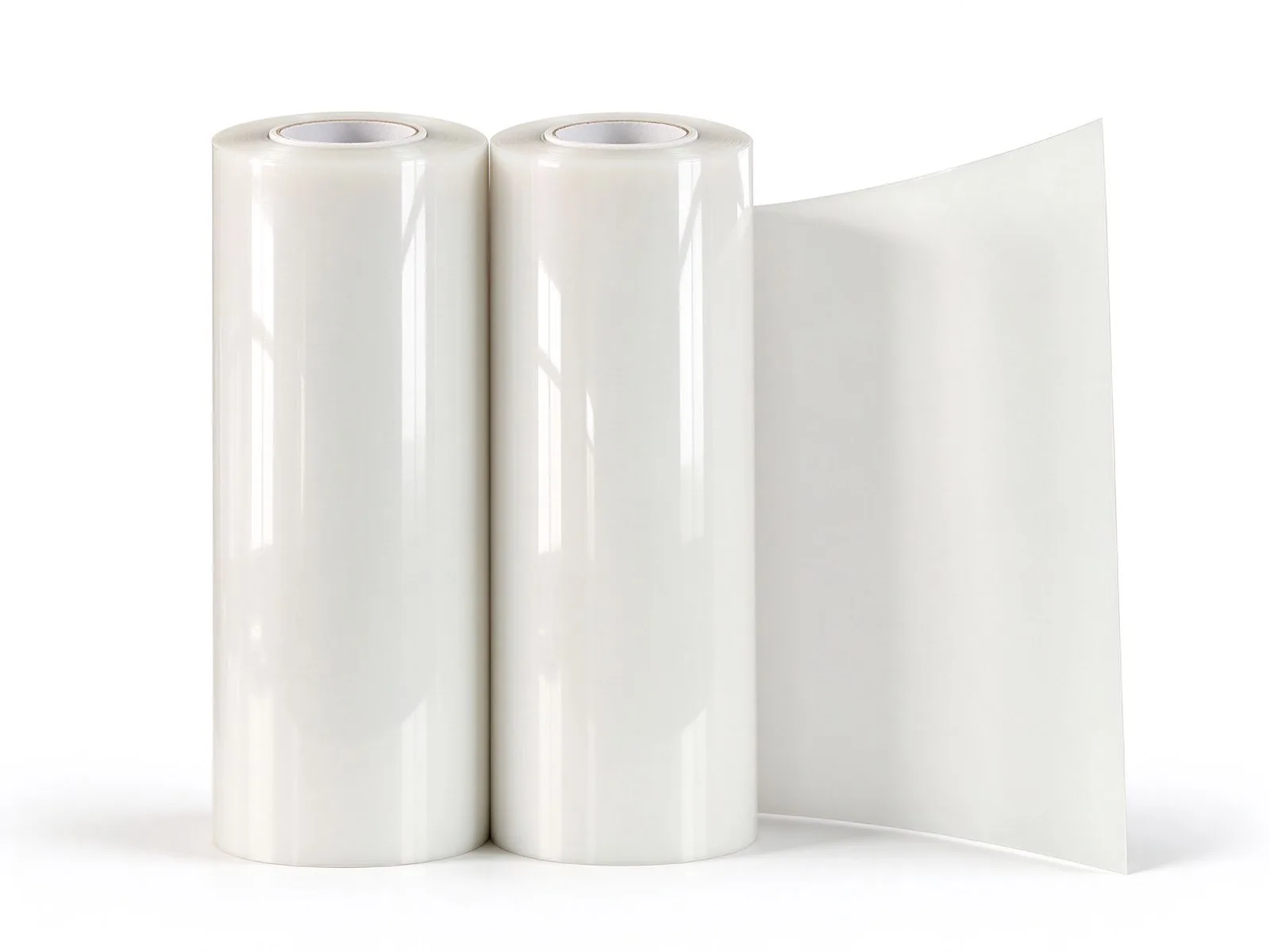
PET, Nomex and DLF epoxy are the three dielectrics we laminate into SHANYUAN busbars every
Read article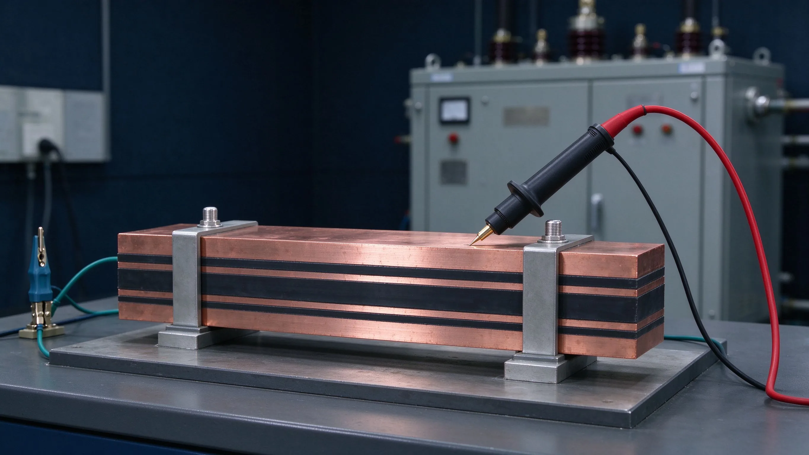
Insulation testing answers four questions: does it withstand rated voltage, does it discha
Read article
Wei Chen is a dielectric and insulation specialist at SHANYUAN, with 12 years in insulation systems for laminated busbars. His work covers PET, Nomex and epoxy powder insulation, creepage and clearance design, and partial-discharge-oriented insulation coordination. He holds a Master's degree in
Send the current profile, voltage class and terminal types — our engineers reply within one business day.
