Infrared thermography is the cheapest predictive test a plant can run on busbar joints, and the easiest to misread. A camera pointed at a cabinet shows a colour map of surface temperature, which is a function of current, ambient, airflow, emissivity and reflection. Without controlling for those, a technician can condemn a healthy joint or clear a failing one. The difference between a useful survey and a photo album is the criteria and the record.
Infrared thermography is the cheapest predictive test a plant can run on busbar joints, and the easiest to misread. A camera pointed at a cabinet shows a colour map of surface temperature, which is a function of current, ambient, airflow, emissivity and reflection. Without controlling for those, a technician can condemn a healthy joint or clear a failing one. The difference between a useful survey and a photo album is the criteria and the record.
First published 6 November 2026 · Last updated 12 November 2026
An IR camera measures radiant flux in a spectral band, usually 7–14 µm for industrial work, and converts it to temperature assuming an emissivity value. The surface of a tinned copper busbar has an emissivity around 0.3–0.5 depending on oxidation and finish; bare polished copper can be below 0.1. If the camera is set to 0.95, the indicated temperature will be wrong by tens of kelvin, usually reading low because reflected background is being interpreted as emitted energy.
The correction matters most at low temperatures. At a 60 °C joint in a 30 °C room, a mis-set emissivity of 0.3 versus 0.95 can shift the reading by more than 15 K, which is the same order as the criterion being applied. Everything downstream depends on getting this right.
The physics behind the correction is straightforward. Every surface both emits and reflects; the camera receives the sum. In a cabinet, the reflected component comes from the enclosure walls, the neighbouring phases and the observer, and at low emissivity that reflected share dominates. Setting the reflected temperature to the actual background, rather than leaving it at the camera default, is the second correction most surveys miss.
Three numbers decide whether a camera can do the job. Resolution: a 160×120 sensor is adequate for scanning large busbars from a metre away, but a 320×240 or better is needed to resolve a single bolted joint in a crowded cabinet. Thermal sensitivity (NETD): 0.05 K or better for condition monitoring, 0.1 K acceptable for qualitative scanning. Instantaneous field of view: the spot size at the target must be smaller than the feature being measured, ideally by a factor of three.
A common error is measuring a 10 mm terminal from a distance where the spot covers 40 mm. The reading then averages the terminal with the surrounding air and insulation, and the hot spot disappears. If the spot cannot be made small enough, move closer or use a close-up lens; do not extrapolate.
Focus is part of the specification too. An out-of-focus image spreads a small hot spot over a larger area and lowers the indicated peak by several kelvin, which is enough to move a joint from the priority band into the watch band. Manual focus, checked on the brightest edge in the field, is more reliable than autofocus in a cabinet full of repeating geometry.
Lens choice follows from the spot-size rule. A standard lens covering 25 degrees at 1 m gives a spot of about 4 mm on a 320-pixel detector, which is enough for a terminal but not for a bolt head at the same distance. A close-up lens reduces the spot by a factor of three and is the right accessory for cabinet work; it costs far less than a higher-resolution camera body.
For a survey, the practical approach is to make the surface uniform rather than to guess a number. A small piece of matte black tape with a known emissivity of 0.95, applied to the joint body, gives a reference reading that can be compared with the surrounding metal. Alternatively, a high-emissivity paint spot serves the same purpose and survives longer.
For tinned busbars specifically, the finish is more uniform than bare copper and a value of 0.4–0.5 is a reasonable starting point if the surface is clean and unpainted. Document the value used, because a survey repeated next year with a different setting is not comparable. Our thermal management note lists emissivity values for the common busbar finishes.
Distance adds an atmospheric term. Over a few metres in a normal plant the correction is negligible. Over 20 m in a humid or dusty environment it is not, and the camera needs the distance, humidity and ambient inputs to compensate. For busbar work the distances are usually short, but outdoor yard surveys are not.
Temperature rise scales roughly with current squared. A joint carrying 30% of rated current runs at less than a tenth of its full-load rise, so a hot joint at low load may look normal. Surveys should be taken at 40% of rated current or more, and ideally above 60%, with the load stable for at least 30 minutes before the image is captured.
If the plant cannot arrange that load, record what the load actually was and treat the result as a screening scan, not a pass. A survey that says 'all joints below 45 °C' at 20% load says almost nothing. The ampacity chart gives the rated values needed to compute the percentage.
The load profile also matters in shape, not just magnitude. A busbar feeding a cyclic load, such as a press or a welder, heats and cools with the cycle, and a single image captures a random instant. For those feeders, capture during the peak of the cycle or use the camera's maximum-temperature capture function over a period rather than a still frame.
An outdoor busbar in direct sun can read 20 K above the air temperature before any current is applied. A cabinet with a cooling fan has a vertical temperature gradient that makes the top joints legitimately hotter than the bottom ones. A joint near a warm transformer radiates into a background that is not the ambient the camera assumes.
The controls are procedural: survey the same cabinet at the same time of day, record ambient and cabinet internal temperature, shield direct sun, and compare joints within the same thermal zone rather than across the installation. If the cabinet has forced cooling, note the fan state, because a failed fan raises every joint and looks like a systemic problem.
Solar gain is worst on galvanised or painted outdoor enclosures, not on the busbar itself. The enclosure heats, the internal air stratifies, and the top joints see an ambient 15 K above the shaded air temperature. Surveying such an installation in the early morning or on a cloudy day removes the variable entirely, which is simpler than modelling it.
IEC 61439-1 sets permissible temperature rise limits for terminals and busbars in low-voltage assemblies, with values that depend on the material, the insulation and whether the part is accessible to touch. For bare copper bars and connections the limits sit in the range of roughly 70–105 K above ambient, and insulated or enclosed parts are lower.
These limits are type-test values for the assembly, not field acceptance criteria for a joint. A joint at 65 K rise inside a cabinet rated to 70 K is passing the standard and may still be a developing failure if its neighbours are at 40 K. That is why absolute limits are used as a ceiling and comparison criteria are used for diagnosis.
The absolute limit also depends on accessibility. A part that can be touched by an operator has a lower permitted temperature than the same part behind a barrier, because the standard is protecting people as well as insulation. Two joints at the same temperature can therefore have different verdicts depending on whether they are inside a closed compartment or on an accessible busbar run.
The most useful field criterion is the phase-to-phase or joint-to-joint difference under the same load. Three phases carrying the same current with identical connections should run within a few kelvin of each other. A spread above about 10 K is worth a second look; a spread above 20 K is a priority finding. For a bolted joint compared with an identical joint on the same bar, a rise of 15 K above its twin is a strong indicator of contact resistance increase.
These thresholds are practice-based rather than standardised, and they depend on how identical the compared parts really are. A joint with a different plating, a different bolt size, or a different airflow is not a valid comparison. Document what was compared and why it was considered equivalent.
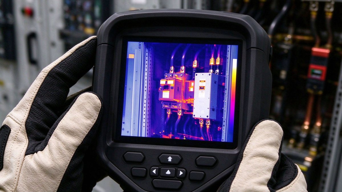
Normalise the comparison for load as well as for geometry. If phase A carries 300 A and phase B carries 240 A, their temperatures differ for a reason that has nothing to do with joint quality. Divide the temperature rise by the square of the current to get a rough comparison, or better, survey at a balanced load so the comparison is valid without correction.
A single survey produces a list of hot spots. A series of surveys produces a degradation curve. If the same joint rises 5 K per year at the same load and ambient, its contact resistance is increasing and the joint will fail within a predictable window. That is the value predictive maintenance is supposed to deliver.
To make trends work, the record must include camera settings, emissivity, distance, load current, ambient, time of day and the exact asset identifier. Without those, the next survey is a new baseline, not a comparison. Store the radiometric image file, not just a JPEG screenshot, so the analysis can be redone.
Baseline images have a second use: they settle disputes. When a joint is replaced under warranty, the before-and-after radiometric files show whether the repair actually reduced the resistance or merely moved the hot spot. That evidence is worth more than a service report written from memory.
A hot joint has excess resistance. The causes, in order of field frequency: insufficient torque, contaminated contact surfaces, plating wear or corrosion, a cracked or undersized terminal, and a loose or missing Belleville washer. Less common: wrong bolt material with a different expansion rate, or a joint never properly cleaned after machining.
The camera cannot distinguish these. It localises the problem, and then a torque check, a contact resistance measurement and a visual inspection assign the cause. Treating the thermal image as the diagnosis leads to re-torquing joints that were already correct and missing the one with a cracked shoulder. See connection design for the joint construction that prevents the common causes.
A useful second check on any hot joint is the symmetry of its neighbours. If two of three phases are hot and the third is normal, the problem is almost certainly local to those two joints. If all three are hot, the load or the ambient is the cause, not the hardware. Reading the pattern before reaching for a torque wrench saves a great deal of unnecessary rework.
A workable routine for a plant with busbar assemblies: a baseline survey at commissioning under a defined load; a quarterly scan of the critical assemblies; an annual full survey with radiometric records; and an immediate scan after any rework, overload event or protection operation. Each scan should take less than an hour per cabinet once the routes are established.
The output should be a ranked list with a recommended action and a date, not a folder of images. Joints above the priority threshold get a resistance measurement within a week; joints in the watch band get a re-scan in one quarter. That structure turns a technician with a camera into a maintenance plan.
Route planning makes the routine practical. Number the cabinets, mark the measurement points on a single-line drawing, and keep the same camera position for each point. A route that takes 40 minutes per cabinet will be done; one that takes three hours will be deferred until after the failure.
IR sees surface temperature, so it misses an internal defect that has not yet reached the surface, such as a void in a laminate or a partially cracked bar inside a heat-shrink boot. It cannot see through a closed panel, and it cannot measure a joint behind a barrier without access. It is also blind to a joint that is hot only under a load condition the survey did not reproduce.
For those cases, complement the camera with partial discharge measurement and contact resistance testing. The three together cover surface heating, insulation defects and joint quality. Our partial discharge note explains where PD testing adds information that thermography cannot.
Clearance and creepage set the air path that a filament or a hot spot has to cross, and those distances are derived in the busbar design guide. Plants running MV equipment should also read how the SF6-free switchgear change altered internal ambient and therefore every baseline temperature.
Safety belongs in the method too. Scanning an open cabinet with the panel removed puts the technician inside the arc-flash boundary. The survey should be planned with the appropriate personal protective equipment and, where possible, performed through an infrared-transparent window with the panel closed. That constraint affects the camera lens choice and the route design, and it should be settled before the first survey rather than during it.
Per cabinet: asset ID, date, time, ambient, internal temperature, load current and percentage of rating, camera model, emissivity setting, distance and lens, fan state, and weather if outdoors. Per joint: location, phase, indicated temperature, corrected temperature, delta against the equivalent joint, and a radiometric file reference. Summary: number of joints scanned, number above the watch threshold, number above the priority threshold, and actions assigned with owners.
A report in this shape can be audited and repeated. A report of pretty images cannot. If you are buying the service from a contractor, put the record format in the purchase order, not in a verbal brief.
The report should also carry the ambient reference used for every rise calculation. Two surveys can produce different verdicts from the same absolute temperatures if one used the cabinet internal air and the other used the room air. Naming the reference makes the numbers comparable across years and across technicians.
Thermography is a screening tool with real diagnostic value only when it is paired with a load condition, an emissivity correction and a comparison baseline. For the busbar supplier, the lesson is that a joint designed for stable contact resistance makes the whole maintenance programme cheaper: fewer hot spots, flatter trends, fewer interventions.
Specify the plating, the torque and the contact resistance window, then hand the plant a baseline survey at commissioning. The camera will confirm the design or find the one joint that was assembled wrong, and either outcome is worth the hour. For joint hardware and terminal details that hold torque, see busbar components.
For assemblies in drives, charging equipment and process lines, the same survey applies; see industrial busbar applications. If a survey finds a joint that cannot be brought back inside the window, the engineering contact route will review the joint design rather than just the torque value.
For the plant, the return is measured in avoided failures rather than in inspection hours. A single prevented cabinet failure typically pays for a year of surveys. For the supplier, the return is a design that does not generate the hot spots in the first place, which is why contact resistance, torque and plating are specified together rather than separately.
One final point on criteria: publish them. A survey programme where the technician applies personal judgement produces inconsistent findings and arguments with the maintenance team. A written criterion, agreed once with the plant engineer and applied unchanged, turns thermography into a measurement rather than an opinion.
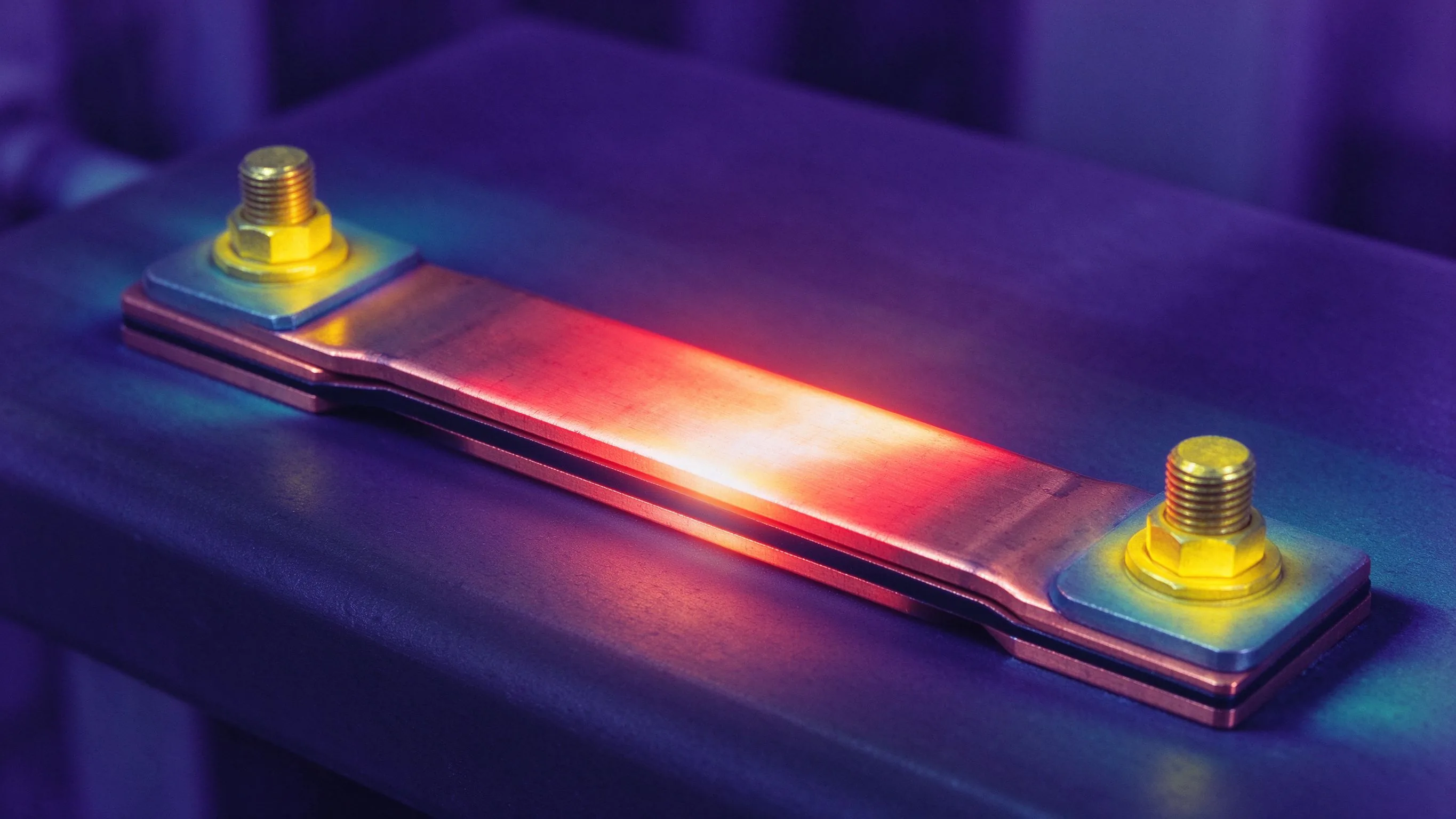
Thermal cycling degrades busbar assemblies from the inside: solder joints crack, bolt pres
Read article
A hipot test proves the insulation did not break down in the second it was stressed. It do
Read article
Nadia Rahman is a quality and compliance engineer with 9 years in electrical-component quality systems. She manages SHANYUAN's ISO 9001 and IATF 16949 programmes, incoming and outgoing inspection, and UL/IEC compliance documentation. She holds a B.Sc. in Industrial Engineering from the Universi
Send the current profile, voltage class and terminal types — our engineers reply within one business day.
