Europe bought about 2.9 million heat pumps in 2025, 13% more than in 2024, and the first half of 2026 added another 1.16 million units across twelve countries, an 11% rise, according to the European Heat Pump Association. The IEA's Heat Pump Monitor recorded a 17% first-quarter increase in Europe. Growth like that is usually discussed as policy and gas prices. The engineering story is quieter: more of those units are inverter-driven, three-phase, and running longer into the shoulder seasons, which changes what the power stage inside them has to survive.
Europe bought about 2.9 million heat pumps in 2025, 13% more than in 2024, and the first half of 2026 added another 1.16 million units across twelve countries, an 11% rise, according to the European Heat Pump Association. The IEA's Heat Pump Monitor recorded a 17% first-quarter increase in Europe. Growth like that is usually discussed as policy and gas prices. The engineering story is quieter: more of those units are inverter-driven, three-phase, and running longer into the shoulder seasons, which changes what the power stage inside them has to survive.
First published 6 November 2026 · Last updated 12 November 2026
This page is an annual rolling data page: the 2026 edition, refreshed once a year as new market data is published.
The EHPA reported roughly 2.9 million domestic heat pumps sold across 21 European countries in 2025, taking the installed stock to about 29.3 million units. In the first six months of 2026, sales in twelve tracked countries reached 1,163,000 units against 1,048,000 in the same period of 2025. The IEA's monitor put European growth at 17% in Q1 2026 and noted that the region accounts for more than 20% of global heat pump sales.
The mix is shifting as well as the volume. Air-to-water monobloc units in the 8–16 kW class dominate renovations, while commercial and district installations move into 30–100 kW banks of modular units. Both trends push the same component: a three-phase inverter with a DC link, a capacitor bank and a busbar that has to fit inside a sealed outdoor casing.
A 12 kW heat pump draws roughly 18 A per phase at 400 V, and a 30 kW commercial unit draws about 45 A. Those numbers are modest by industrial drive standards, which is why heat pump power stages were once built with cables and terminal blocks. As units gained inverter control for part-load efficiency and low-noise operation, the DC link became a switching node with a loop inductance problem rather than a wiring problem.
A laminated busbar that places the positive and negative rails directly above each other cancels most of the stray field and cuts loop inductance to a few nanohenries. That reduces the voltage overshoot across the IGBTs at turn-off, which in turn allows a faster switching edge and lower switching loss. The gain is real: a well-designed DC-link bar can remove 30–50% of the overshoot compared with a cable link at the same current. Our low inductance design note explains the geometry that produces it.
The inductance argument is quantifiable. A cable link with 300 mm of loop length and roughly 20 nH per 100 mm contributes about 60 nH, and at a 400 A/us turn-off that is 24 V of overshoot on top of the DC link. A laminated bar with the two rails 0.3 mm apart and a 120 mm loop can bring the total under 10 nH, cutting the overshoot to about 4 V. That difference is what allows a 650 V IGBT to run on a 600 V DC link without a snubber, and it is why the bar is specified by inductance rather than by current alone.
Heat pumps run hardest in the coldest weeks and barely at all in mild weather, but the inverter still operates through the shoulder seasons for domestic hot water and cooling. The component consequence is a high number of thermal cycles over a life of 15 years, with relatively few hours at full load.
This is the opposite of a server power supply, which runs continuously at high load, and it changes the failure ranking. Solder joints and capacitor connections see repeated expansion rather than long steady heat. A busbar bolted to an aluminium heat sink with a single bolt will ratchet loose over thousands of cycles; a bar with two-point clamping and a spring washer will not. The thermal management guidance covers the interface materials that survive that regime.
The compressor is the load that shapes the current. A scroll compressor at part load draws a modulated current with a strong low-frequency envelope, and the inverter tracks it at 8-20 kHz. The busbar therefore sees a thermal cycle at the modulation rate superimposed on the seasonal cycle, which is why the joint has to be stable at both time scales. A joint that is fine thermally but frets mechanically will still fail, and a joint that is tight but has poor thermal contact to the heat sink will overheat at part load where airflow is lowest.
Most European residential heat pumps use a 400 V three-phase supply and switch at 8–20 kHz. At 16 kHz in copper, current penetrates only about 0.5 mm from the surface, so a 2 mm bar does not use its full section for the switching component of the current. The DC component still uses the whole section, which is why DC-link bars are sized on average current and checked for AC loss rather than sized on RMS.
The practical rule is to keep the bar thin enough that the skin depth covers most of the thickness, or to accept the loss and manage the temperature. A 1.5 mm copper bar at 16 kHz is a reasonable compromise: the AC resistance penalty is modest, and the thin section helps the thermal path to the heat sink. Our ampacity chart gives the DC baseline and the derating factors.
The formula for skin depth is worth keeping: delta = square root of (2 rho / (omega mu)). For copper at 16 kHz that works out to about 0.52 mm, so a 1.5 mm bar uses roughly a third of its thickness for the switching component and the rest for the DC component. That is why thin, wide bars outperform thick, narrow ones at the same copper mass, and why a design that simply scales a 50 Hz bar up in thickness does not get the loss reduction it expects.
The DC-link capacitor is the component that actually supplies the switching current. If the capacitor sits at the far end of a long bar, the loop inductance includes the bar, and the capacitor's own ESL dominates. If it sits directly across the IGBT terminals with the bar folding around it, the loop is small and the bar becomes a low-inductance connection rather than a transmission line.
Mechanically this is awkward in a heat pump because the PCB, the capacitor bank and the compressor terminals compete for the same space near the condenser. Designers end up with a U-shaped or L-shaped laminated bar that wraps the capacitor. Each bend adds inductance and a stress concentration, so the bend radius and the layer registration have to be specified together. The connection design note covers the bend rules for thin laminates.
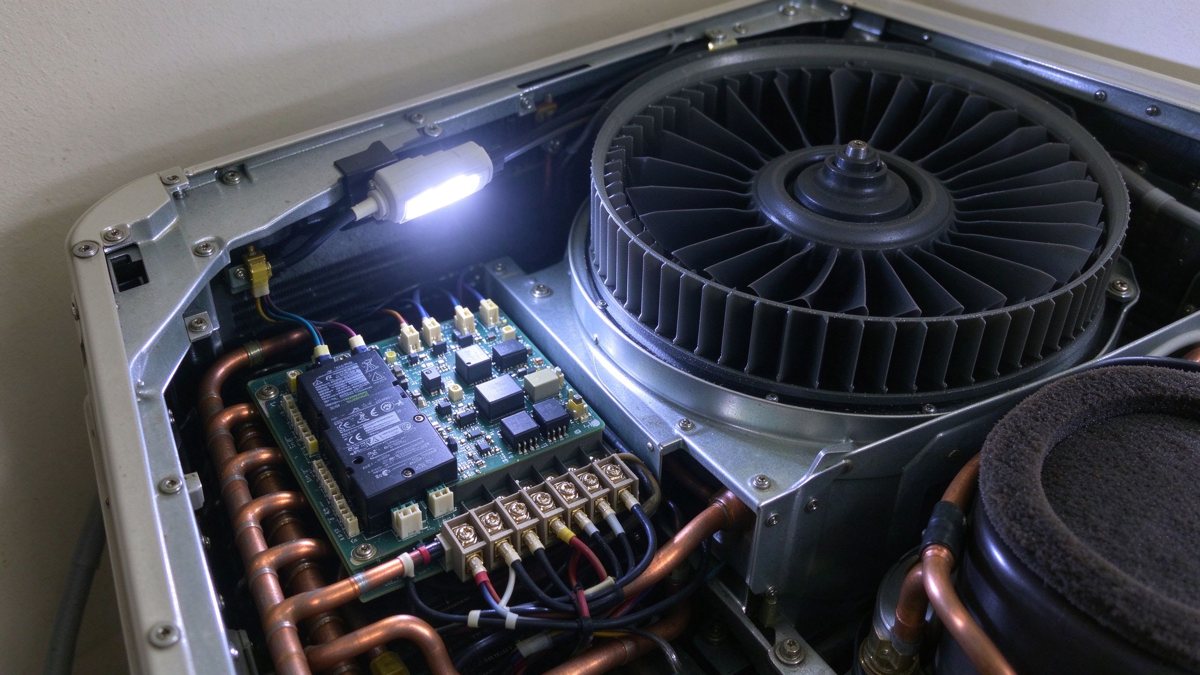
The equivalent series inductance of the capacitor is the floor the bar can reach. A film capacitor in a radial can has 5-15 nH of internal ESL; no busbar geometry can beat that, so the design goal is to add as little as possible on top. That is why the bar is often folded directly over the capacitor terminals rather than routed across the board, and why capacitor selection and bar layout are decided together rather than sequentially.
A heat pump sits outdoors. The electrical enclosure is usually IP54 or better, but it breathes: internal pressure changes with temperature, and moisture enters through seals over years. Coastal installations add chloride. The busbar sees humidity cycling without direct water, which is the condition that produces creep corrosion on tin plating and tracking across an uncleaned laminate edge.
Specification choices that help: tin plating over a nickel barrier rather than tin directly on copper, a conformal coat on the bar edges where the laminate is cut, and a potting or gasket at the terminal exit. All three add cost and all three are cheaper than a field return. The quality process page describes the humidity and salt-spray sequences we run on outdoor assemblies.
Condensation is a design condition, not an accident. A heat pump that runs a defrost cycle drops the evaporator coil below zero and then returns to normal operation; the cabinet can pass through the dew point twice a day in humid weather. Any surface that stays below the dew point collects water, and any crevice on the busbar holds it. Drainage paths, a slight tilt on horizontal surfaces and a potting compound at the terminal exit are the cheap countermeasures.
Propane (R290) is attractive because it has low global warming potential, and it is increasingly used in monobloc heat pumps. It is also flammable, which means the electrical compartment must not be an ignition source. For the busbar this translates into a requirement that connections do not arc or spark in normal operation and that a loose joint is detected before it becomes hot enough to ignite a refrigerant leak.
In practice, that pushes designers toward clamped or welded joints rather than sliding contacts, toward temperature sensing near the DC link, and toward a creepage distance that assumes condensation may occur. It also makes the terminal torque specification a safety document rather than a process note. See terminal machining for the shoulder and thread details that hold torque in a vibrating casing.
The ignition argument changes the failure analysis. With R290, a loose joint that develops a hot spot is not only an electrical fault; it is a potential ignition source in an enclosure that may contain refrigerant. Standards for A3 appliances require the electrical compartment to be separated or assessed as non-ignition, which pushes designers toward clamped or welded joints and toward a temperature sensor on the DC link that trips before the terminal reaches the safety margin below the refrigerant auto-ignition temperature.
Heat pumps are sold on sound power. A unit that switches at 8 kHz can produce an audible tone at the compressor's modulation frequency; moving to 16–20 kHz pushes the tone above the most sensitive part of the hearing range but raises switching loss and requires a faster edge.
The busbar participates in both problems. A low-inductance bar allows a faster edge, which reduces overlap loss but increases radiated EMI, so the shielding and the return path have to be designed together. A bar with a dedicated return layer, or a laminated bar bonded to a grounded chassis plate, is usually the cheapest way to keep the emissions inside the enclosure. This is a case where the same geometry that helps electrically also helps EMC.
Acoustic noise in a heat pump comes from three sources: the fan, the compressor shell and magnetostriction in the reactor. The busbar contributes indirectly through the current ripple it permits. A bar with higher inductance forces a slower edge and a larger ripple, which increases the low-frequency current in the reactor and its hum. Reducing loop inductance therefore has an acoustic benefit that is rarely credited in the electrical budget.
A heat pump DC-link bar is small, often under 200 mm long, and is assembled by the thousand on an automated line. The tolerances that matter are not the ones on the drawing's overall length but the ones at the interfaces: hole position relative to the IGBT module pins, laminate thickness consistency across the bar, and flatness at the capacitor mounting face.
A 0.2 mm positional error at a module pin will not stop assembly, but it will bend the pin and reduce the contact area, which shows up as a hot pin after two seasons. A 0.1 mm thickness variation changes the press fit of the capacitor. Both are process capabilities, not design features, and both should be agreed with the supplier before tooling. Our fabrication tolerance guide sets out the values that are achievable at series volume.
Flatness is the tolerance that causes the most production trouble. A laminated bar that bows by 0.3 mm over 150 mm will not seat on the heat sink without bending the module pins, and the assembly station compensates by over-torquing, which stresses the laminate. Specifying flatness after press and after bend, with a straightness callout on the mounting face, is the way to stop that chain.
Three tests belong at unit level. A hipot on the assembled DC link proves the laminate and the creepage path. A partial discharge measurement at 1.2× the DC-link voltage catches voids that hipot misses. A thermal run at maximum modulation, in a chamber at 45 °C ambient, proves the capacitor and the bar together.
The third test is the one that most often reveals a layout problem, because the capacitor's hot spot and the bar's hot spot are not in the same place and the unit's internal airflow decides which one dominates. Test the assembly as it ships, with the casing closed, or the result will not predict the field.
The order of tests matters. A hipot before the thermal run will pass a bar with a marginal creepage path; the same bar after a thermal run may fail because the insulation has absorbed moisture or the laminate has moved. Running the electrical test last, on a unit that has been through the thermal and humidity sequence, gives a result that predicts the field rather than the factory.
Laminated copper DC link: lowest inductance, best for 16 kHz and above, higher unit cost, needs controlled press and bend processes. Solid copper bar with insulation: cheapest, adequate below 8 kHz where overshoot is tolerable, poor for tight layouts. Aluminium bar: lighter and cheaper on material, but 60% conductivity means a larger section and a different terminal strategy. PCB-embedded copper: excellent for very small units, limited current and thermal mass, best under 10 kW.
For a 12–16 kW monobloc the laminated copper link is the default. For a 6–8 kW unit with a lower switching frequency, a solid bar with an insulated boot can be adequate, provided the overshoot is measured rather than assumed.
An RFQ for a heat pump DC-link bar should include: DC-link voltage and switching frequency, continuous and peak phase current, maximum loop inductance in nH, capacitor mounting geometry, ambient and internal temperature, humidity and salt-spray class, refrigerant safety category, terminal type and torque, laminate material and thickness, test requirements (hipot, PD, thermal), and annual volume with the expected model variants.
Because the part is small and cheap, it is tempting to buy on price from a catalogue. That works until the model changes and the bar has to be re-tooled in six weeks. The sample-to-series sequence is designed for that timeline and keeps the first article tied to the volume ramp.
Volume structure belongs in the RFQ as well as the technical fields. A platform with three output sizes sharing one bar can commit to a higher annual volume than three separate part numbers, and that changes both the tooling amortisation and the price break. Buyers who send three drawings separately pay three tooling charges for one platform.
The policy direction in Europe is toward more electrification, not less, and the 2026 rebound suggests the market has absorbed the subsidy reset. The engineering direction is toward larger monobloc units, more R290, and quieter operation, all of which raise the electrical duty on the same small footprint.
For busbar suppliers, the opportunity is not in selling a bigger bar. It is in holding inductance, temperature and process capability together at a price that a heat pump manufacturer can accept across a family of models. That is a design-service offer, not a catalogue offer. If you are specifying a DC link for a new platform, the custom engineering route starts with the layout, not the drawing.
Two related decisions sit upstream of the DC link. The plating stack that survives years of humidity cycling is covered in the tin whisker mitigation guide, and the commercial side — how tooling, MOQ and inventory change the landed cost of this small part — is in the procurement TCO framework.
The refrigerant transition and the efficiency targets are both pushing units toward higher DC-link voltage and faster switching, which raises the value of a good bar and lowers the tolerance for a mediocre one. At the same time, cost pressure is pushing toward aluminium and PCB-embedded solutions at the low end. The split will probably settle around 10 kW: below it, integrated solutions; above it, laminated copper with a real thermal path.
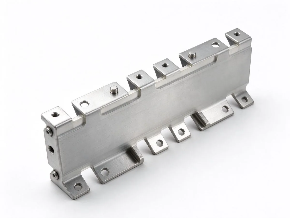
The inverter that dominated 2026's solar tenders is no longer a small box: 300 kW-plus str
Read article
Loop inductance decides how hard a SiC converter can switch. This guide covers the double-
Read article
Emily Novak analyses energy-storage, grid and new-energy markets and turns them into procurement-ready technical content. With 7 years in energy market research and technical writing, she covers BESS growth, HVDC projects and regulatory shifts that change busbar demand. She holds an M.A. in Energy E
Send the current profile, voltage class and terminal types — our engineers reply within one business day.
