Custom LV switchgear busbar routed to NEC-compliant panels, retrofits and CT/PT installations - send a drawing for engineering review.
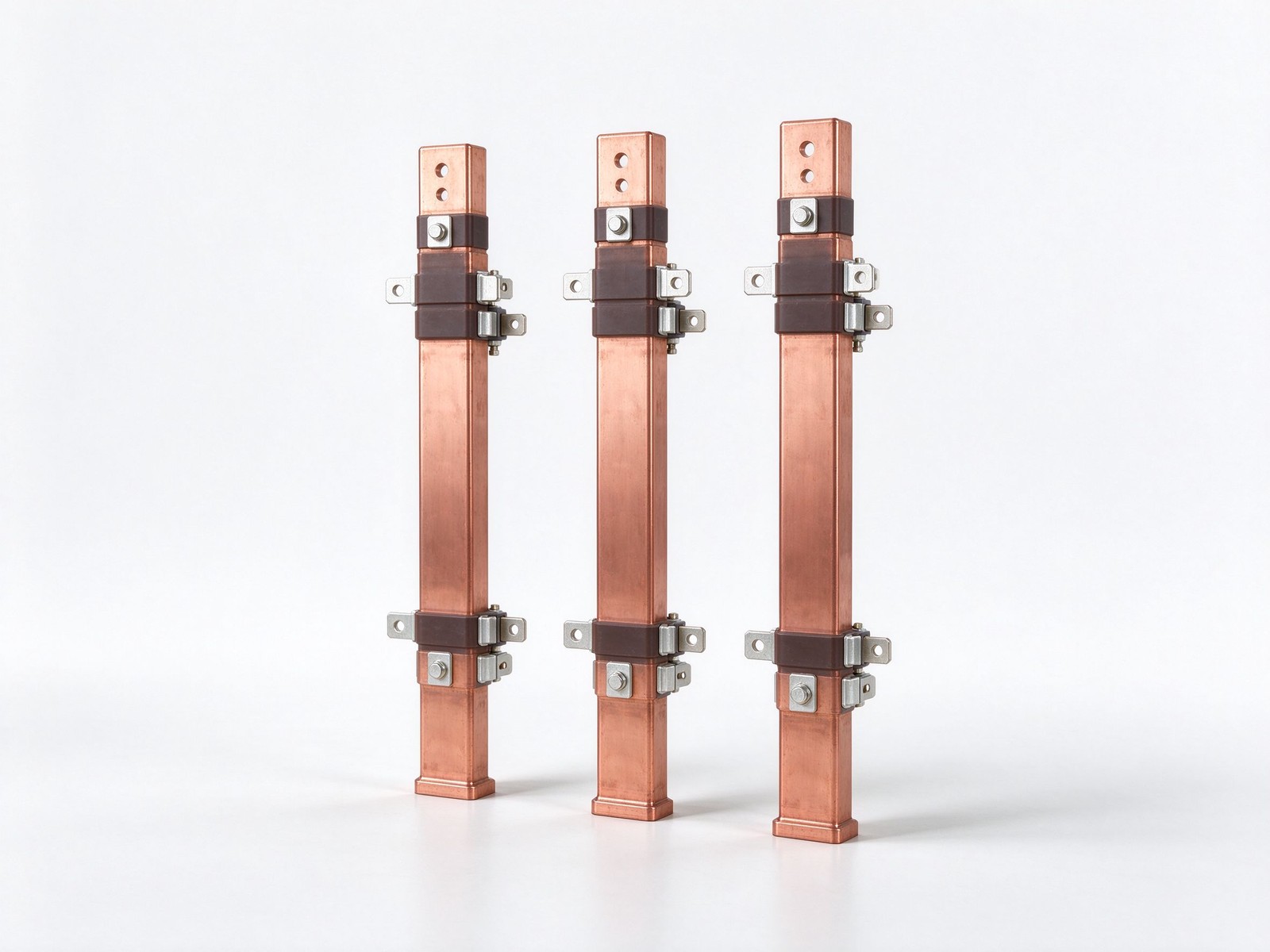
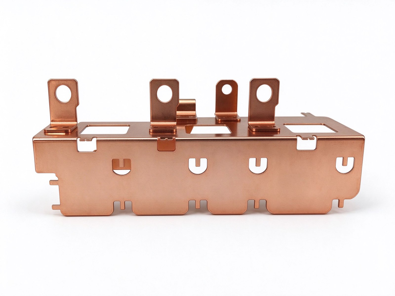
Product imagery: factory photo plus studio renders. The exact geometry, layers and terminals of your part follow your drawing.
Final values follow your drawing — this is the standard configuration of the family.
| Parameter | Value |
|---|---|
| Conductor | C11000 copper, aluminium option |
| Function | Feeds all branch overcurrent circuits |
| Layout | Custom to panel, breaker and starter footprint |
| Finishes | Bare, tin-plated, fully dielectric insulated |
| Instrument gear | CT / PT mounting geometry built in |
| Options | Modular shrouds, DIN-rail mounting |
| Standards | NEC / NEMA / ANSI; IEC 61641 arc-fault |
| SKU | SY-PE-216 |
Key characteristics of this product family.
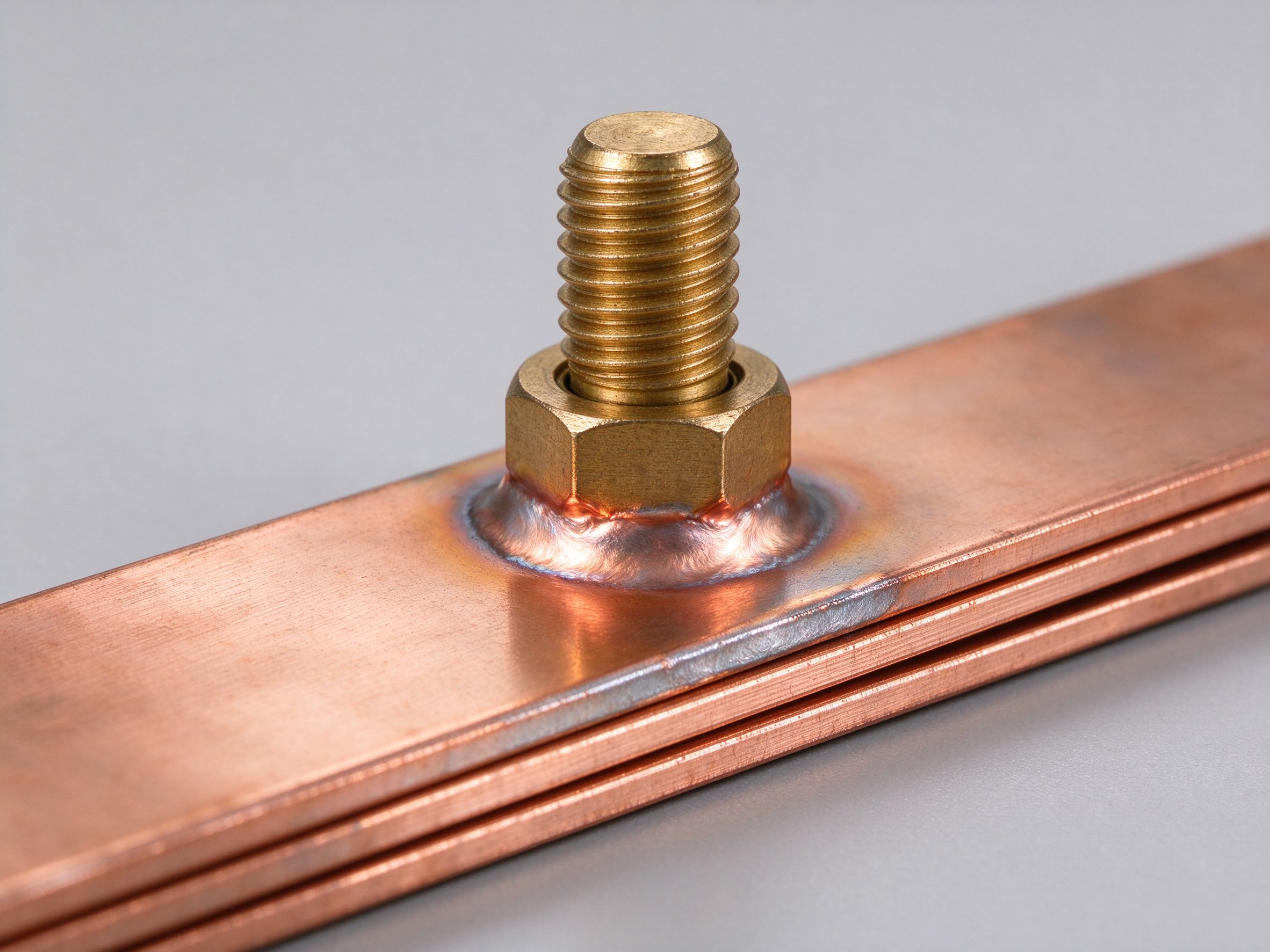
An LV switchgear busbar routes the low- and high-voltage conductors inside control panels and switchgear enclosures, feeding incoming power to every branch overcurrent circuit in a clean, code-compliant layout. It has to satisfy NEC overcurrent-protection and line-voltage switching arrangements, respect panel clearance rules, and leave room for breakers, metering and future modifications.
Most custom switchgear bars originate at retrofit time. A new breaker frame size, a solid-state trip unit or a motor-starter upgrade rarely matches the hole pattern of the bar already fitted in the panel. A custom-fabricated copper bar re-matches the new hardware to the existing cabinet footprint, so an upgrade stops being a whole-panel rebuild.
Five situations recur on our drawing desk. High-ambient installations - foundries, refineries and chemical plants run panels hot, so the conductor section is up-sized against the elevated-temperature derating curve. Mixed-OEM retrofits - panels carrying breakers, contactors and starters from several makers collide on mounting hardware, and the custom bar is drawn to fit each one. Digital tenant metering - branch current transformers need a flat, accessible mounting face on every feeder. Instrument-transformer mounting - CT and PT positions are built into the bar geometry, so commissioning and later changes stay simple. Modular shrouds and DIN-rail mounting - bar-shaped shrouds keep live parts covered and make mounting repeatable.
In harsh locations the bar carries full dielectric insulation, which also shrinks the installation footprint, plus electroplated coatings that hold back surface corrosion. Design references NEC, NEMA and ANSI panel practice, and where arc-fault containment matters, IEC 61641 defines internal-arc-fault testing for low-voltage switchgear and controlgear assemblies.
Related builds: solid insulated copper busbar and epoxy-insulated copper bar.
Dust, moisture, chemicals and outdoor exposure attack both the conductor and its joints. Full dielectric insulation shrinks the panel footprint while covering live copper; electroplated coatings - tin, nickel or silver - cut surface corrosion on contact faces. Where internal arc faults must be contained, IEC 61641 sets the internal-arc-fault testing method for low-voltage switchgear and controlgear assemblies, alongside NEC, NEMA and ANSI panel practice. Dielectric options: insulating films and heat-shrink insulated busbar.
Send the single-line diagram, breaker list and cabinet envelope to the custom busbar design service; a DFM review and sizing proposal return within one business day. Background: power distribution basics.
An LV switchgear busbar routes incoming power to every branch overcurrent circuit inside a panel, so the impedance of the bus run decides voltage drop and fault current distribution rather than switching overshoot. Values below are planning estimates for panel runs quoted for retrofit and new switchgear builds, assuming a 500 mm panel depth unless another panel depth applies.
| Panel Bus Run | Conductor Form | Run Length (typ.) | Loop Impedance (est.) | Drop at 630 A (typ.) |
|---|---|---|---|---|
| Single bare copper bar per phase | Rectangular bar, 50 × 6 mm | 500 mm | ≈ 18 µΩ / 120 nH | ≈ 11 mV / phase |
| Two bars per phase, stacked | 2 × 50 × 6 mm, insulated | 500 mm | ≈ 9 µΩ / 70 nH | ≈ 5.7 mV / phase |
| Laminated phase-neutral bar | Face-to-face, 0.5 mm gap | 400 mm | ≈ 8 µΩ / 25 nH | ≈ 4.5 mV / phase |
| Switchgear busbar retrofit, existing hole pattern | Formed bar to old holes | varies | matched to original | kept within original drop |
| CT PT mounting busbar, metering run | Bar through CT window | 300 mm | low nH, metering-grade | negligible at metering class |
Resistive drop is the main number here: R = ρ × L / A with ρ ≈ 0.0172 Ω·mm²/m for copper at 20 °C, and loop inductance matters mainly for fault-current rise. A panel busbar NEC compliant layout respects the clearance rules in addition to the impedance budget; the creepage and clearance design note covers the spacing rules, and the power distribution resources page lists panel-rating context. Bus bars are typically supplied in C11000 tin-plated copper for panel service.
An LV switchgear busbar terminates on the devices inside the panel rather than on a power module, so the tab geometry is cut to the breaker, fuse or CT terminal. The list below is the device families we tool panel bars for, with the terminal patterns most often seen in NEC-compliant switchgear and retrofit builds; hole spacing is planned to the device manufacturer mounting dimension.
| Device Family | Terminal Pattern | Bar Form We Tool | Typical Panel Use |
|---|---|---|---|
| Moulded-case circuit breaker (MCCB) | Line / load screw lugs | Flat bar, drilled to lug spacing | Branch and feeder protection |
| Air circuit breaker (ACB) | Main bus studs, M10–M12 | Heavy bar, formed to stud layout | Main incoming and tie |
| Low-voltage power fuse / fuse holder | Blade or screw fuse end | Formed bar to fuse holder jaw | DC and AC feeder protection |
| Current transformer (CT) window | Bar passes through CT bore | Straight bar, metering grade | Metering and protection circuits |
| Potential transformer (PT) terminal | Screw terminal block | Small formed tab | Voltage sensing and control |
| Cu busbar clamp / connector | Bolted clamp face | Formed bar to clamp width | Retrofit joins to existing buswork |
Send the panel drawing and the device datasheets; the DFM review locks hole pattern, bar width and torque pad against both. A switchgear busbar retrofit is usually driven by a new breaker frame size that no longer matches the existing holes, so the bar is tooled to the new device while keeping the panel mount spacing. The short-circuit withstand guide covers the mechanical bracing check, and the contact page opens the drawing review. Torque pads are milled flat to the device lug face, and the bolt size is selected to match the manufacturer's recommended tightening torque for the busbar cross-section. Bar thickness is typically 3 to 6 mm for feeder runs.
Where this busbar configuration earns its place.
Where this busbar configuration earns its place.
Where this busbar configuration earns its place.
Where this busbar configuration earns its place.
Where this busbar configuration earns its place.
Where this busbar configuration earns its place.
Your drawings reach the engineers who build the part.
Design risks flagged when changes are cheap.
Test records per lot, CoC and PPAP on request.
Drawing to delivered production parts, one supplier.
From spec review to shipped, tested parts — one accountable supplier.
Straight answers from the engineering team.
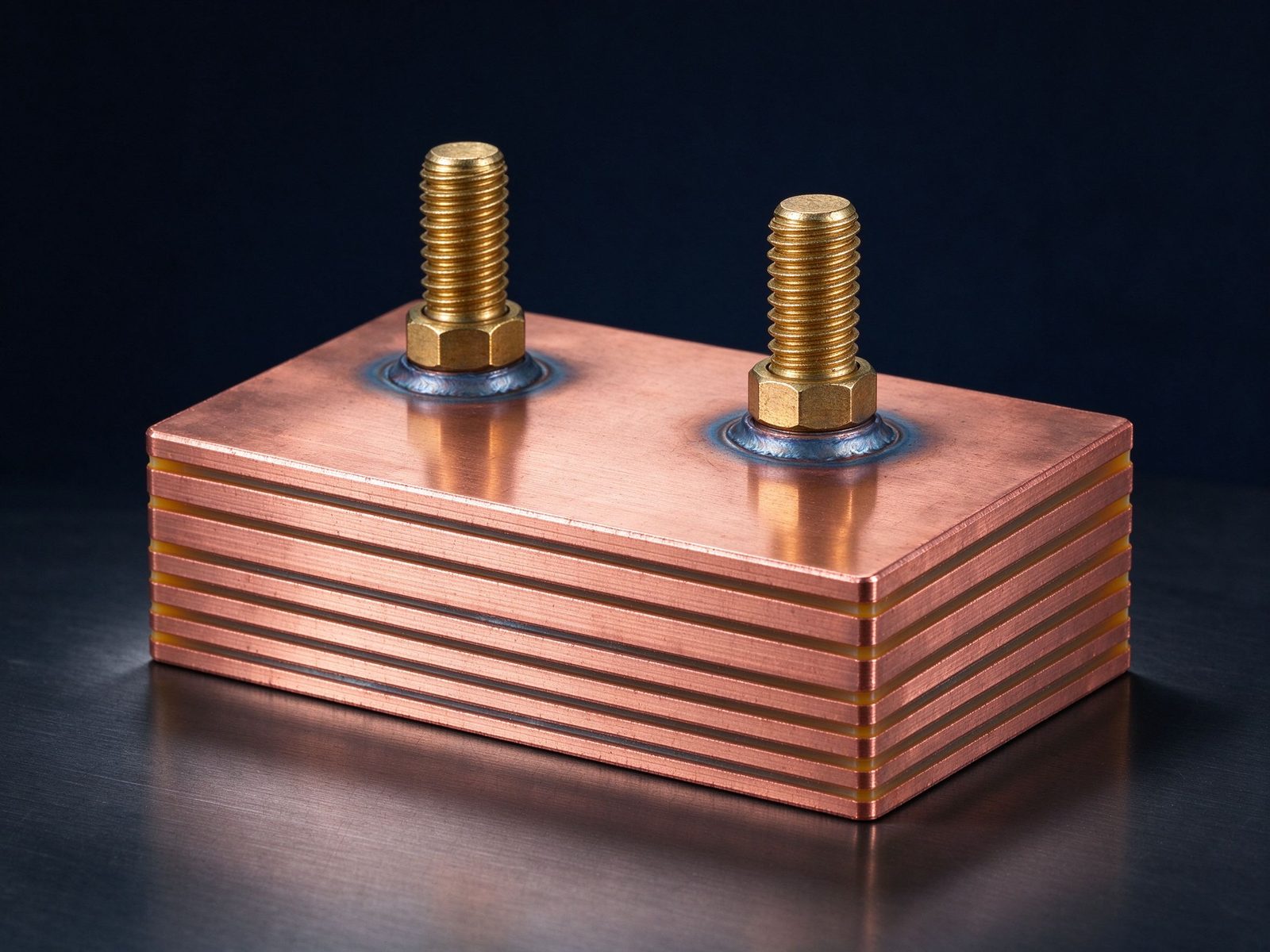
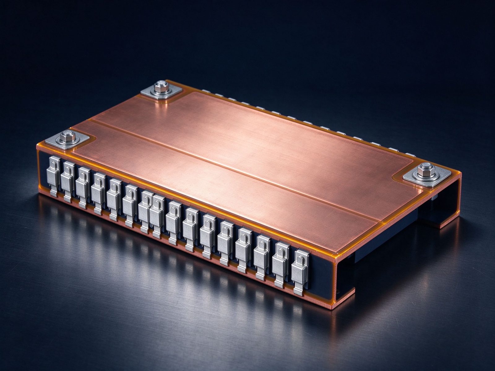
Every SHANYUAN busbar is custom, but the power circuits they connect recur across markets. Three typical ones — send us yours and we will point to the right stack-up.
Tight, low-inductance links between the battery source and traction inverters, fully edge-sealed for 400–800 V platforms.
Commutation-loop connections from DC-link capacitors to IGBT bridges, designed against switching overshoot V = L × di/dt.
Converter DC links built for rising bus voltages toward 1500 VDC, with creepage and partial-discharge margins included.
Construction, dielectric selection and current capacity basics.
Read the busbar design guideLayers, terminals, dielectrics and mounting are all configurable. Send us your spec for DFM review and a quotation within one business day.
